|
|

|
Porsche, and the Porsche crest are registered trademarks of Dr. Ing. h.c. F. Porsche AG.
This site is not affiliated with Porsche in any way. Its only purpose is to provide an online forum for car enthusiasts. All other trademarks are property of their respective owners. |
|
|
  |
| Mike Bellis |
 Mar 13 2013, 04:07 PM Mar 13 2013, 04:07 PM
Post
#161
|
|
Resident Electrician      Group: Members Posts: 8,346 Joined: 22-June 09 From: Midlothian TX Member No.: 10,496 Region Association: None 

|
|
| Andyrew |
 Mar 13 2013, 05:41 PM Mar 13 2013, 05:41 PM
Post
#162
|
|
Spooling.... Please wait           Group: Members Posts: 13,377 Joined: 20-January 03 From: Riverbank, Ca Member No.: 172 Region Association: Northern California 
|
Ah, that should work great then.
|
| Mike Bellis |
 Mar 30 2013, 07:18 PM Mar 30 2013, 07:18 PM
Post
#163
|
|
Resident Electrician      Group: Members Posts: 8,346 Joined: 22-June 09 From: Midlothian TX Member No.: 10,496 Region Association: None 

|
I've been creating a custom pedal cluster for the 914. I needed a hydraulic clutch and I wanted to keep the stock-ish brake master cylinder. I run a bigger master to push on the 930 calipers. The brakes work great so I did not want to mess with them.
I used Howe pedals but everything else is custom. The clutch cylinder is from Wilwood. This was the second attempt. The first one set the pedals back too far. In the original design, I used the Howe pivot brackets. In order to make it work with the brake master in the factory position, I needed to lower the elevation of the rod. The howe rod pivot point was 3/4" too high. This would have made an extreme angle for the rod into the master. I came up with an articulating rail system for the stock rod. I also needed to offset the rod to the right of the pedal. You can see all the mechanics of it here and in motion in the video. I added a second pivot to carry the side load created by the offset. After fabrication, I hardened all the parts and shot it with a coat of satin black. The new cluster will weld to the factory cluster floor bracket and bolt to the floor so it can be removed as an assembly. I did have to cut a hole into the fuel tank cavity for part of the clutch master to fit into the space. The fluid hose will be placed in the cabin with grommets to the reservoir in under the hood. I tested the pedal torque by placing a C clamp in front of the sliding rail. Clamp was tight and the pedal was able to pop the clamp right off the assembly. I can't tell you the exact torque, I was more concerned with binding or breakage of the system. It appears the brakes should work fine with this setup. You will see a couple of switches. One for the brakes and one (micro, spring, limit switch) for the clutch for cruise control deactivation. 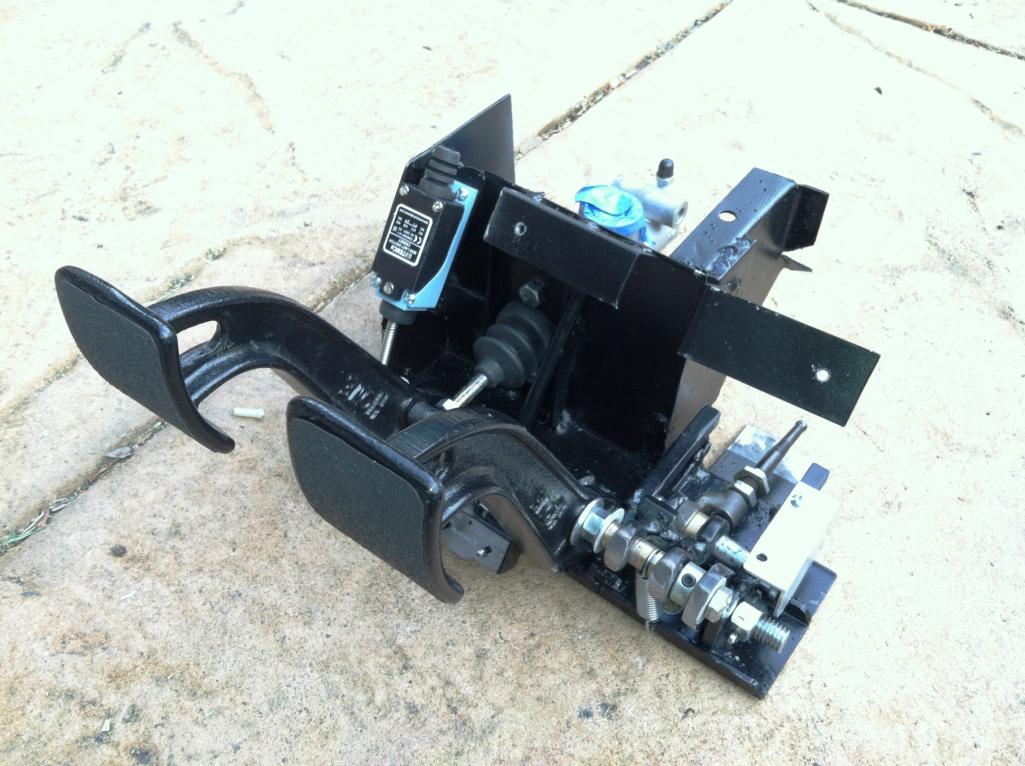 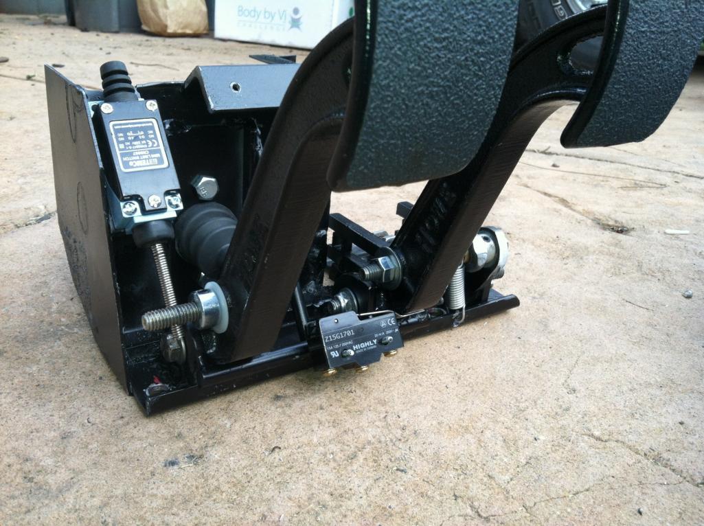 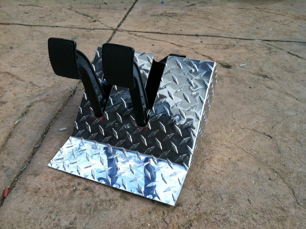 https://www.youtube.com/watch?v=PEBmgYdJ_Ow |
| Andyrew |
 Mar 30 2013, 07:27 PM Mar 30 2013, 07:27 PM
Post
#164
|
|
Spooling.... Please wait           Group: Members Posts: 13,377 Joined: 20-January 03 From: Riverbank, Ca Member No.: 172 Region Association: Northern California 
|
Wow thats a lot of bits on that brake lever... Looks extremely smooth but a bit complicated.
|
| Mike Bellis |
 Mar 30 2013, 07:31 PM Mar 30 2013, 07:31 PM
Post
#165
|
|
Resident Electrician      Group: Members Posts: 8,346 Joined: 22-June 09 From: Midlothian TX Member No.: 10,496 Region Association: None 

|
Wow thats a lot of bits on that brake lever... Looks extremely smooth but a bit complicated. What? (IMG:style_emoticons/default/confused24.gif) I only count 20 individual pieces... (IMG:style_emoticons/default/biggrin.gif) It would have been much less if I would have moved the master cylinder... |
| JStroud |
 Mar 30 2013, 07:42 PM Mar 30 2013, 07:42 PM
Post
#166
|
|
Senior Member    Group: Members Posts: 1,463 Joined: 15-January 11 From: Galt, California Member No.: 12,594 Region Association: Northern California |
That's awesome Mike. (IMG:style_emoticons/default/piratenanner.gif)
Looks like things are coming together nicely, can't wait to see it finished.......finished (IMG:style_emoticons/default/av-943.gif) I crack myself up sometimes. Your the man Mike, looking great! Jeff |
| andys |
 Mar 30 2013, 09:10 PM Mar 30 2013, 09:10 PM
Post
#167
|
|
Advanced Member     Group: Members Posts: 2,165 Joined: 21-May 03 From: Valencia, CA Member No.: 721 Region Association: None 
|
Mike,
I like your "modular" concept. Keep up the good work! Andys |
| Mike Bellis |
 Mar 30 2013, 09:29 PM Mar 30 2013, 09:29 PM
Post
#168
|
|
Resident Electrician      Group: Members Posts: 8,346 Joined: 22-June 09 From: Midlothian TX Member No.: 10,496 Region Association: None 

|
Mike, I like your "modular" concept. Keep up the good work! Andys I think your work is more impressive! Thanks for the kind words! (IMG:style_emoticons/default/smile.gif) |
| jaxdream |
 Mar 31 2013, 08:04 AM Mar 31 2013, 08:04 AM
Post
#169
|
|
Senior Member    Group: Members Posts: 974 Joined: 8-July 08 From: North Central Tennessee Member No.: 9,270 Region Association: South East States |
Just noticed that you are going to use VW column controls !! (IMG:style_emoticons/default/piratenanner.gif) Great I've had 2005 VW controls for a while , got the ideas of getting the updated wiper function of the little wheel on the stalk to do intermitten , also on the signal side the dimmer switch thing . Also got a wiper motor to match , which appears to have the same bolt pattern as 914 wiper rack along with the propper relay to operate . It'll be great to see what you come up with , as well as the reat of the mods !!! Thanks for this thread , it does give hope of alternatives to the base VW systems of the 70s. (IMG:style_emoticons/default/cheer.gif)
Jack |
| Mike Bellis |
 Mar 31 2013, 10:14 AM Mar 31 2013, 10:14 AM
Post
#170
|
|
Resident Electrician      Group: Members Posts: 8,346 Joined: 22-June 09 From: Midlothian TX Member No.: 10,496 Region Association: None 

|
Just noticed that you are going to use VW column controls !! (IMG:style_emoticons/default/piratenanner.gif) Great I've had 2005 VW controls for a while , got the ideas of getting the updated wiper function of the little wheel on the stalk to do intermitten , also on the signal side the dimmer switch thing . Also got a wiper motor to match , which appears to have the same bolt pattern as 914 wiper rack along with the propper relay to operate . It'll be great to see what you come up with , as well as the reat of the mods !!! Thanks for this thread , it does give hope of alternatives to the base VW systems of the 70s. (IMG:style_emoticons/default/cheer.gif) Jack I did swap the column for all the reasons you mention... Plus + Cruise Control! I also swapped out the VW steering wheel for an Audi sport unit. The new Porsche steering wheels bolt right on too but they are pricey! I'm not ready to spend $1000 for a wheel and air bag. But it would look cool... |
| Mike Bellis |
 Apr 6 2013, 10:36 PM Apr 6 2013, 10:36 PM
Post
#171
|
|
Resident Electrician      Group: Members Posts: 8,346 Joined: 22-June 09 From: Midlothian TX Member No.: 10,496 Region Association: None 

|
Pedal cluster is in, sort of. I did not do the final welding yet. (in case I need to take it out) I had to compromise on the throttle pedal location. The perfect mounting alignment position would require the removal of the steering shaft. But then I couldn't turn. (IMG:style_emoticons/default/sad.gif) Ideally it would be a little higher but I don't want to raise the fresh air box area. But it seems OK when I sit in the seat and make engine noises... VROOM!... I got the clutch master bench bled and plumbed to the rear. Right now I just have a -3AN plug in the back since the motor has to come out still for final bolt tightening and minor chassis welding.
I also picked up a FireCharger AFFF fire system. Pretty cool and it allows me to re-charge it at will. I still need to plumb it to the engine bay and rig the pull handle, so for now I just have the location of the bottle mocked up. I picked up a short shifter for the boxster assembly. The Boxster shift knob is a press on fit to a flat bar. So.. I cut the Lever off, drilled, tapped and installed a Mustang lever. I topped it off with a Hurst style knob with the proper 5-spd pattern embossed on top. You can see the wire frame/fiberglass console I made to snap over the shifter assembly. I cut a gauge hole in it for a future something. Maybe a vintage VW clock... (IMG:style_emoticons/default/idea.gif) Please excuse the wiring hanging. I will dress it up once I'm sure all the wiring is complete. 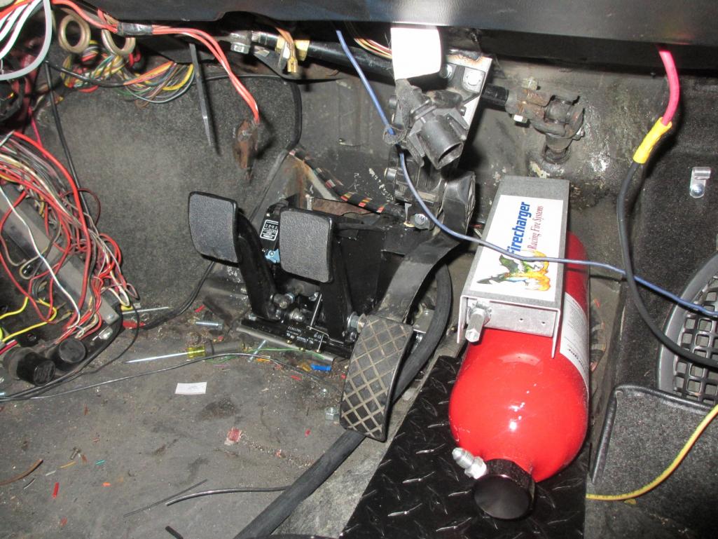 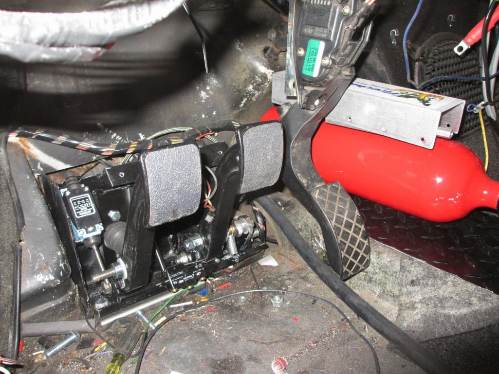 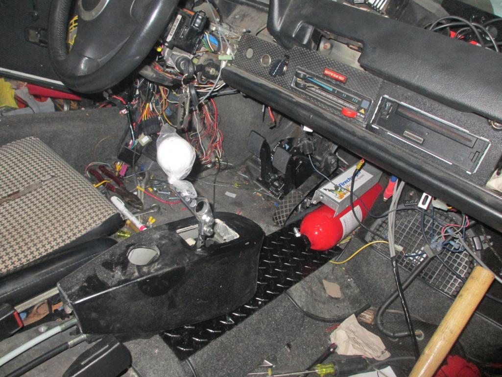 (IMG:style_emoticons/default/type.gif) Here you can see a teaser shot of my Rat Rod 1936 Buick parking brake setup. It's modified (like everything else) to work with my hydraulic parking system. 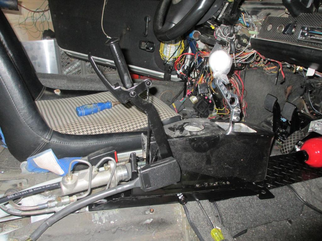 |
| 76-914 |
 Apr 7 2013, 07:27 AM Apr 7 2013, 07:27 AM
Post
#172
|
|
Repeat Offender & Resident Subaru Antagonist           Group: Members Posts: 13,634 Joined: 23-January 09 From: Temecula, CA Member No.: 9,964 Region Association: Southern California 
|
(IMG:style_emoticons/default/thumb3d.gif) Nice pedal cluster, Mike.
|
| JRust |
 Apr 7 2013, 10:28 AM Apr 7 2013, 10:28 AM
Post
#173
|
|
914 Guru      Group: Members Posts: 6,310 Joined: 10-January 03 From: Corvallis Oregon Member No.: 129 Region Association: Pacific Northwest 
|
That sub in the passenger footwell looks sweet (IMG:style_emoticons/default/evilgrin.gif)
|
| Mike Bellis |
 Apr 7 2013, 09:18 PM Apr 7 2013, 09:18 PM
Post
#174
|
|
Resident Electrician      Group: Members Posts: 8,346 Joined: 22-June 09 From: Midlothian TX Member No.: 10,496 Region Association: None 

|
I had a bit of bad luck today, although I solved it too.
I was drilling for some rivets to hold down the aluminum diamond plate tunnel cover. The fourth one I drilled I sment gas. (IMG:style_emoticons/default/sad.gif) I had to cut the tunnel open to get to the hard line. Yep... Hole through and through. Since the fuel system is already complete and I didn't fell like re-plumbing, I got a compression coupler from HD supply and fixed it. The aluminum hard lines use -6AN compression fittings anyway. They are designed for a brass ferrule, so I figured the brass compression fitting will be fine. It was a pain cutting the tunnel open with my air saw. No sparks! There is a small boxed section on the passenger side next to the shifter. When I ran the hard lines, one of them made it into this small cavity. It is just big enough for the 3/8" line to fit through. (IMG:style_emoticons/default/dry.gif) Good thing I picked up some .023 wire last week. This made rewelding the thin sheet metal easier. All fixed! I then switched to plumbing the fire system. Might come in handy some day... (IMG:style_emoticons/default/biggrin.gif) Lesson of the day... Know where your fuel lines are! |
| andys |
 Apr 7 2013, 10:01 PM Apr 7 2013, 10:01 PM
Post
#175
|
|
Advanced Member     Group: Members Posts: 2,165 Joined: 21-May 03 From: Valencia, CA Member No.: 721 Region Association: None 
|
|
| Mike Bellis |
 Apr 7 2013, 10:12 PM Apr 7 2013, 10:12 PM
Post
#176
|
|
Resident Electrician      Group: Members Posts: 8,346 Joined: 22-June 09 From: Midlothian TX Member No.: 10,496 Region Association: None 

|
Say Mike, your seatbelt doesn't look to be stock 914; the cable to latch looks somewhat longer, if I'm not mistaken. What are you using, and will it couple with the stock 914 seat belt tongue? Andys It came with a set of belts I picked up at McMark's swap meet. The whole setup looks just like the 914 set I took out except for the latch. And yes the 914 belt does lock in; Same shape plug. My wife didn't like the old 914 belts and the latch was too short for her comfort. So I swapped it out. I haven't done the drivers side yet, as you can see in the picture. |
| McMark |
 Apr 8 2013, 01:11 AM Apr 8 2013, 01:11 AM
Post
#177
|
|
914 Freak!                Group: Retired Admin Posts: 20,179 Joined: 13-March 03 From: Grand Rapids, MI Member No.: 419 Region Association: None |
It's a 944 seat belt setup.
|
| Mike Bellis |
 Apr 13 2013, 11:31 PM Apr 13 2013, 11:31 PM
Post
#178
|
|
Resident Electrician      Group: Members Posts: 8,346 Joined: 22-June 09 From: Midlothian TX Member No.: 10,496 Region Association: None 

|
I pulled the motor today in order to finish some odds and ends. Just about every peripheral component needed to be tightened down. I had to make custom 12mm wrenches to get the exhaust bolted on. There isn't much space and a conventional box wrench would not work. I have about a dozen custom tools fabbed up for the series of engine swaps.
The methanol injector was mounted to the outlet of the intercooler. This is a 330cc injector good for 350hp @ 7500 rpm. Right in my range. Notice the tip is recessed. In theory, this allows the spray to form a "cone" before the air flow (passing by) cuts into the stream. By doing this it promotes better atomization. There is some debate on other forums about installing the injector within the intercooler. The argument revolves around pooling inside the cooler. In my case, I am running a solenoid before the injector to prevent dribble thus avoiding pooling. In addition, the injector will not open below 10psi and/or an analog signal from the MAF. 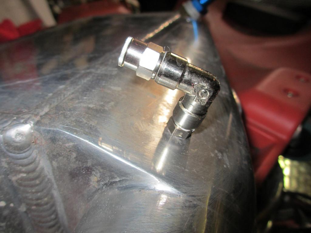 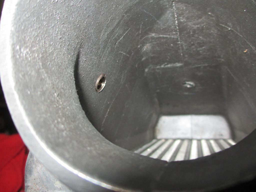 The Audi/VW motors suffer from sludge build up in the PCV system. There was even some law suit over it. I decided to mitigate problems by using a crankcase evacuation system. 034 Motorsport hooked me up with a machined aluminum fitting that plugs into the system. I added some 5/8" aluminum hard line and brass compression fittings. This is the main line that heads to a custom built 1 gallon catch can. From the catch can the line continues to the vacuum venturi welded to the exhaust. This type of system is usually found on V8 drag cars. As the exhaust flows past the venturi a vacuum is pulled on the system- on the engine crank case. It was originally designed to help seal rings on high HP engines. So I get the best of both worlds. Reduced sludge and better sealing combustion chambers. 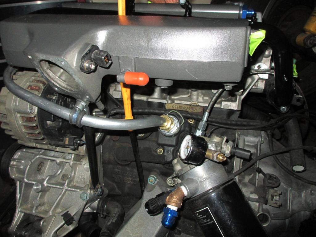 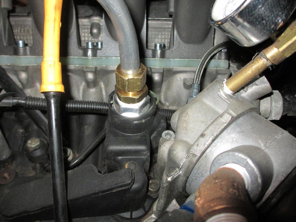 Here is a pic of the turbo oil drain. I used the lower original oil drain and some high temp hose with an -10AN fitting. After cutting the factory stainless hard line, I rolled a bead on it to keep the hose in place. I finally got to use my mini bead roller! 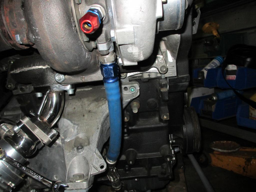 |
| Mike Bellis |
 Apr 13 2013, 11:43 PM Apr 13 2013, 11:43 PM
Post
#179
|
|
Resident Electrician      Group: Members Posts: 8,346 Joined: 22-June 09 From: Midlothian TX Member No.: 10,496 Region Association: None 

|
As I mentioned before, an AFFF fire system has been installed. This system is approved by many racing sanctioning bodies. This system from FireCharger is also refillable by me at any time. I runs off a compressed CO2 cylinder. You just need a refill kit and water. Very easy! I am more concerned with putting out a fire than weather or not the car will pass tech. I still keep fire extinguishers in the car any way.
The bottle and CO2 housing are mounted on the front tunnel. I mounted the handle on my shifter console. The nozzle tubing is routed on top of the tunnel, up the firewall and pops out into the engine bay at the top. The two nozzles are mounted slightly to the left of center. One over the fuel rail and one over the intake manifold. I painted the top of the tips red so they don't blend in to the rest of the stuff back there. 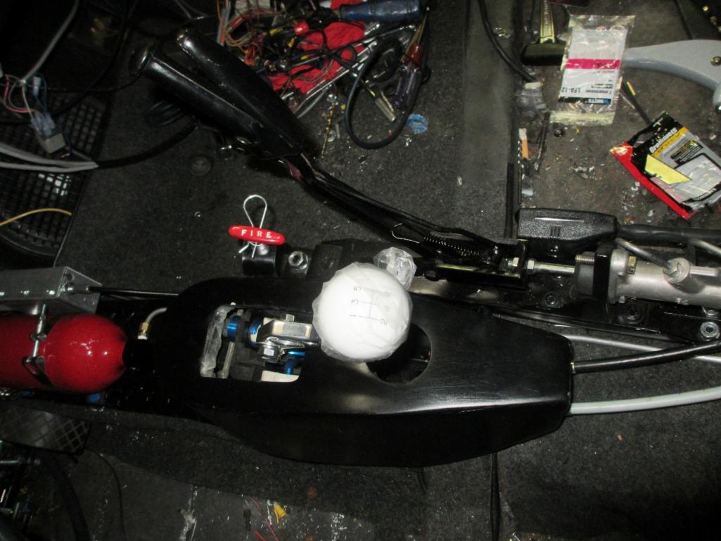 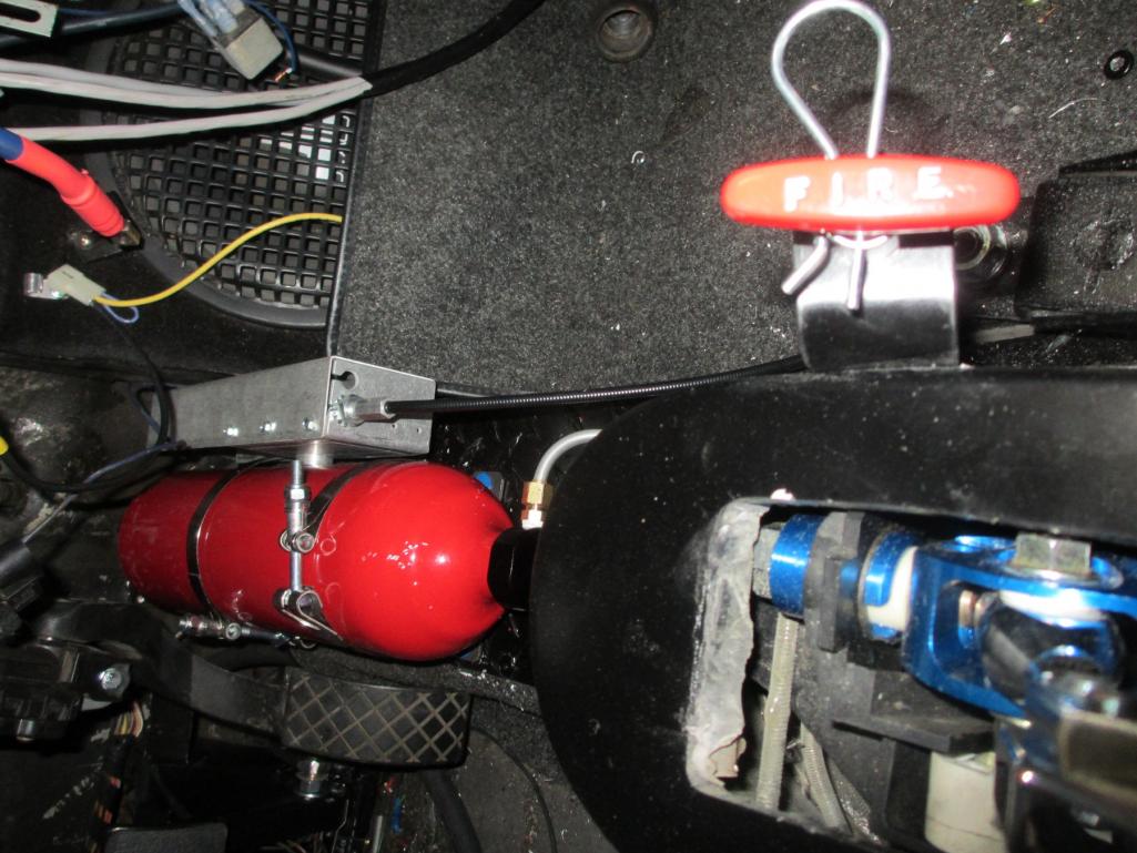 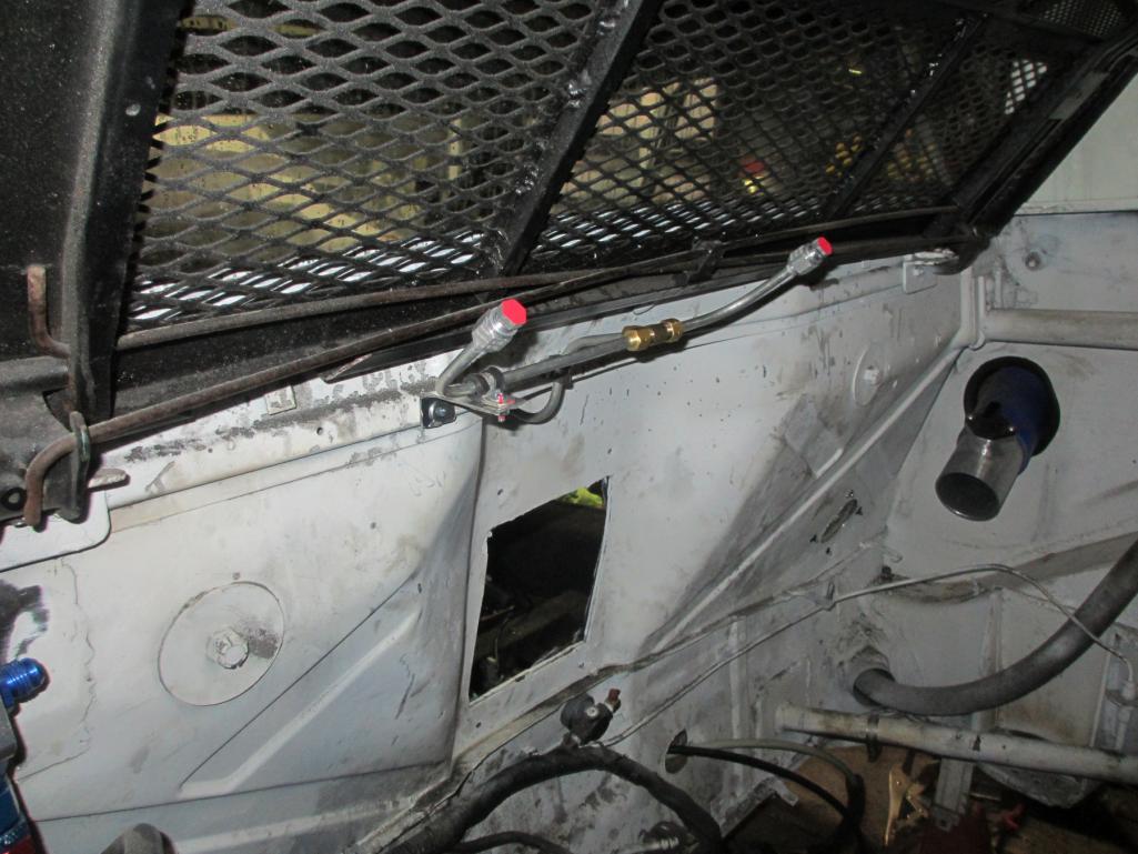 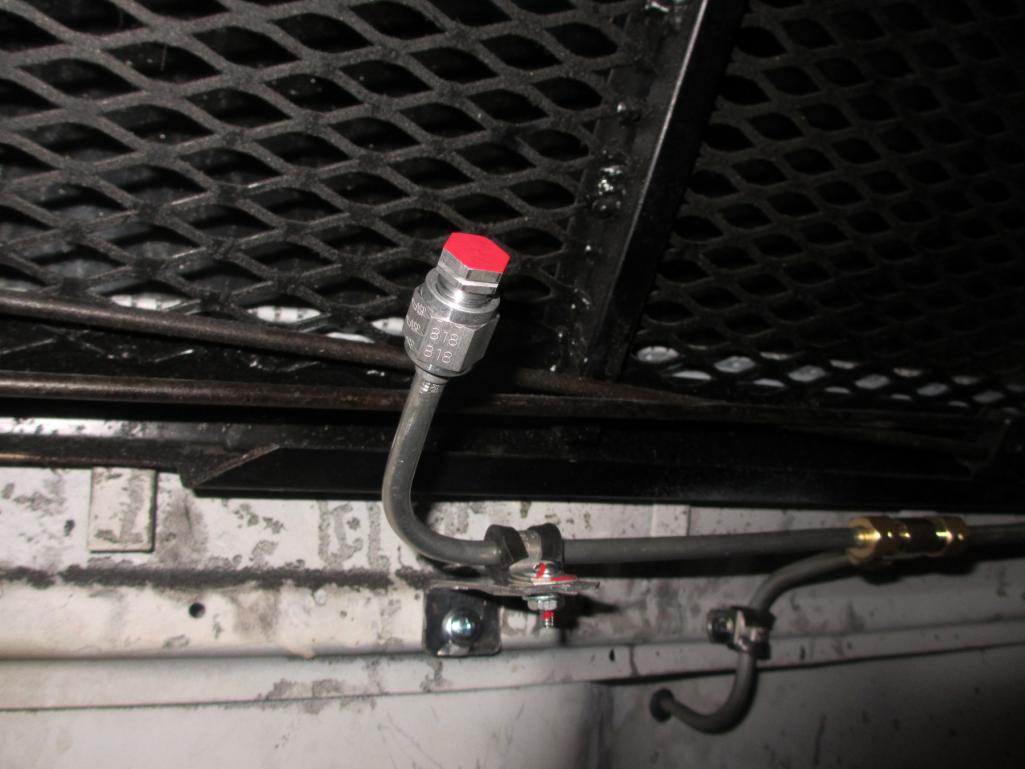 |
| Cairo94507 |
 Apr 14 2013, 07:28 AM Apr 14 2013, 07:28 AM
Post
#180
|
|
Michael           Group: Members Posts: 10,095 Joined: 1-November 08 From: Auburn, CA Member No.: 9,712 Region Association: Northern California 
|
Your skills just blow me away. I like the way you have laid stuff out and look forward to seeing this car back on the road. Great work Mike.
I will have a fire suppression system in my Six just because. I also think a nice small handy fire extinguisher is worth having in the car too. Probably mount one of those at the front of the passenger seat. |
  |
4 User(s) are reading this topic (4 Guests and 0 Anonymous Users)
0 Members:

|
Lo-Fi Version | Time is now: 26th November 2024 - 08:29 AM |
Invision Power Board
v9.1.4 © 2024 IPS, Inc.


