|
|

|
Porsche, and the Porsche crest are registered trademarks of Dr. Ing. h.c. F. Porsche AG.
This site is not affiliated with Porsche in any way. Its only purpose is to provide an online forum for car enthusiasts. All other trademarks are property of their respective owners. |
|
|
  |
| Literati914 |
 Apr 17 2024, 09:54 AM Apr 17 2024, 09:54 AM
Post
#181
|
|
Senior Member    Group: Members Posts: 1,780 Joined: 16-November 06 From: Dallas, TX Member No.: 7,222 Region Association: Southwest Region |
In order to improve the airflow into the frunk mounted AC condenser, has anyone tried creating an air inlet by opening up the holes behind the front bumper that have the biground rubber plugs, like guys who run 914-6 engines do when building a front mounted oil cooler and ducting into the frunk floor? GT opening for a condenser instead of oil cooler or radiator (Suby/v8 cars). Sounds like the way to go if you are serious about a/c. It’s the optimal location for airflow. I like this idea the best.. would A GT opening (both bumper and Valance) be sufficient for air to the condenser? I suppose even at GT oil cooler shroud could be incorporated and may even help the flow? Thoughts? . |
| technicalninja |
 Apr 17 2024, 10:06 AM Apr 17 2024, 10:06 AM
Post
#182
|
|
Advanced Member     Group: Members Posts: 2,123 Joined: 31-January 23 From: Granbury Texas Member No.: 27,135 Region Association: Southwest Region 
|
You're already in...
I wouldn't waste my time on that itsy bitsy core. You live in HELL! Design accordingly... You're already there! I'd get my tape measure out and figure out how big a core you can fit. Depending on your hose set up a proper big single core might just fit. The connections will be the same most likely... #8 and #6. |
| friethmiller |
 Apr 17 2024, 11:40 AM Apr 17 2024, 11:40 AM
Post
#183
|
|
Senior Member    Group: Members Posts: 667 Joined: 10-February 19 From: Austin, TX Member No.: 22,863 Region Association: Southwest Region 
|
You're already in... I wouldn't waste my time on that itsy bitsy core. You live in HELL! Design accordingly... You're already there! I'd get my tape measure out and figure out how big a core you can fit. Depending on your hose set up a proper big single core might just fit. The connections will be the same most likely... #8 and #6. (IMG:style_emoticons/default/idea.gif) I think/know you're right. So, pull air from a new hole/intake from the valance/bumper area. Screw the bottom intake crap and use the entire area for the condenser and fan. This seems like a better way to go. I'm all for it! |
| friethmiller |
 Apr 17 2024, 04:53 PM Apr 17 2024, 04:53 PM
Post
#184
|
|
Senior Member    Group: Members Posts: 667 Joined: 10-February 19 From: Austin, TX Member No.: 22,863 Region Association: Southwest Region 
|
@technicalninja - I called and talked with one of the techs at old air. He said parallel flow condensers should not be mounted flat - like I have. It must drain to the smaller, liquid side. Crap! More redesign. I may just put on a better 12” fan, increase the intake air, and see how it goes (IMG:style_emoticons/default/wacko.gif)
|
| technicalninja |
 Apr 17 2024, 06:58 PM Apr 17 2024, 06:58 PM
Post
#185
|
|
Advanced Member     Group: Members Posts: 2,123 Joined: 31-January 23 From: Granbury Texas Member No.: 27,135 Region Association: Southwest Region 
|
I disagree with him...
Read my previous posts. I've covered the oiling issue already. Lots of things have condensers and evaporators at not "textbook" angles. Don't automatically believe every expert you speak with. Most are FAR less expert than they think they are... He is RIGHT about vertically mounted condensers needing the input at the top and the exit at that bottom. Do it backwards and the reaper awaits. Laying the condenser flat is not a deal killer. I'm more worried about fan life myself... |
| Chris914n6 |
 Apr 17 2024, 11:57 PM Apr 17 2024, 11:57 PM
Post
#186
|
|
Jackstands are my life.     Group: Members Posts: 3,423 Joined: 14-March 03 From: Las Vegas, NV Member No.: 431 Region Association: Southwest Region |
From what I can tell what you have now should work fine. The dealer options worked fine.
You need a PULLER fan. Pushers don't work worth a turd. If TN was right you can just reverse the wires on the fan you have and it will actually work as designed. Skinny fans won't move much air, so it becomes a space issue. The Chinese don't do CFM measurements, they just copy and most of their fans under preform. If the current fan doesn't cut it buy a thick Spal fan. The cardboard duct can be trashed. It would be better to structure the opening further forward under the spoiler/bumper with it flowing wide and shallow to the cond inlet. The mouth can be as big as needed but really your limited to the area of the exit hole. Pardon my crude drawing, but this should solve most of the problems by changing placement and maybe a new enclosure. (IMG:http://www.914world.com/bbs2/uploads_offsite/live.staticflickr.com-431-1713419868.1.jpg) |
| friethmiller |
 Apr 18 2024, 09:28 AM Apr 18 2024, 09:28 AM
Post
#187
|
|
Senior Member    Group: Members Posts: 667 Joined: 10-February 19 From: Austin, TX Member No.: 22,863 Region Association: Southwest Region 
|
From what I can tell what you have now should work fine. The dealer options worked fine. You need a PULLER fan. Pushers don't work worth a turd. If TN was right you can just reverse the wires on the fan you have and it will actually work as designed. Skinny fans won't move much air, so it becomes a space issue. The Chinese don't do CFM measurements, they just copy and most of their fans under preform. If the current fan doesn't cut it buy a thick Spal fan. The cardboard duct can be trashed. It would be better to structure the opening further forward under the spoiler/bumper with it flowing wide and shallow to the cond inlet. The mouth can be as big as needed but really your limited to the area of the exit hole. Pardon my crude drawing, but this should solve most of the problems by changing placement and maybe a new enclosure. Thanks Chris. A few things I like about this design is that it trades exhaust for more intake space, which I need. Additionally, the puller fan set-up. That said, as you mentioned, the enclosure would likely need to be increased in height (at a minimum). The existing condenser is 14"x12"x1" and it sits inside a 16"x16"x4" box. Another issue I'm dealing with is the full-sized spare tire. It mounts to the top of the box and I have a factory style funk cover on top of that. I've customized this cover to work with everything. I guess I'm trying to find the optimal solution here based on my constraints. Again, thanks for your input, TN's, and others. I'll keep this all in mind moving forward. Just based on expenses, I may implement something quick to improve the current situation then plan and execute on a better, more permanent fix later this year. |
| 914sgofast2 |
 Apr 18 2024, 12:52 PM Apr 18 2024, 12:52 PM
Post
#188
|
|
Senior Member    Group: Members Posts: 655 Joined: 10-May 13 From: El Dorado Hills, CA Member No.: 15,855 Region Association: None |
I would change that design by having the outside air enter the front of the air box, instead of the bottom. That way it is similar to how many people mount front oil coolers for the 914-6 engines in the frunk when they collect the cooler outside air thru the front bumper cutout, instead of from under the frunk floor, and then exhaust the air under the car from the frunk floor, similar to how the original A/C systems exhausted their hot air under the car. This would require building some metal ducting from the front bumper area to the original A/C air box' front and opening up the front of that air box. Think of how Mike Cairo's Six Project is making a new front oil cooler housing.
|
| friethmiller |
 May 3 2024, 02:00 PM May 3 2024, 02:00 PM
Post
#189
|
|
Senior Member    Group: Members Posts: 667 Joined: 10-February 19 From: Austin, TX Member No.: 22,863 Region Association: Southwest Region 
|
A/C Condenser Fix (Phase1):
First off, thanks for the all the input on this one. Thanks to @dlee6204 , who doesn't complain about me hijacking his thread. After a lot of thought and consideration, I decided to go with the condenser I have in the car for just a little while longer. I wanted to ditch the small, inaccessible box and build up something that I can later modify with a larger unit and perhaps a different configuration. I started with the bottom screen. I needed to enlarge the condenser's intake opening (pics 1 &2). I finally welded in the grill mesh to make it one component (pic 3). It was a sandwich before (IMG:style_emoticons/default/confused24.gif) (Don't blame me, I was only following the kits instructions before). This made it much easier to handle and install. Once completed, I repainted and reinstalled the bottom screen. Note the cuts made to the floor to increase the the intake (see black arrow). The intake went from an opening of 2 3/4" x 12.5 to a larger 4" x 14" . Still not great but it's a good improvement. 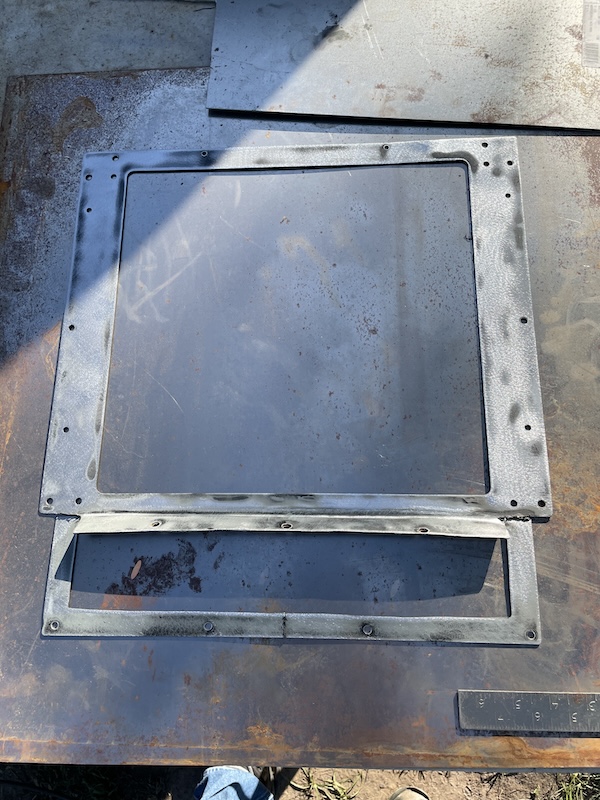 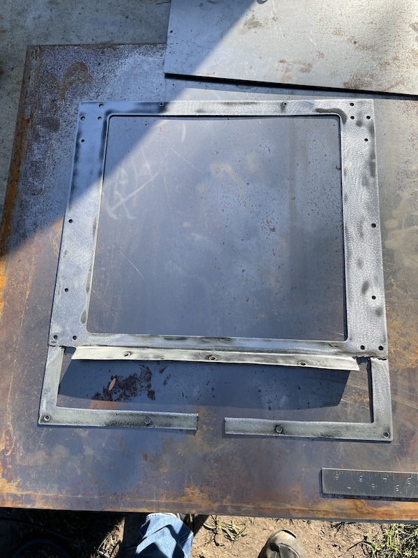 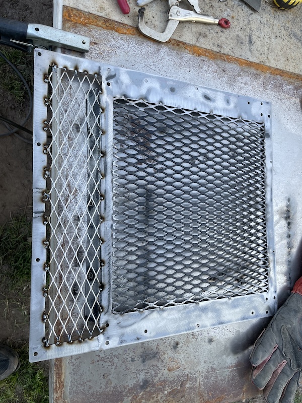 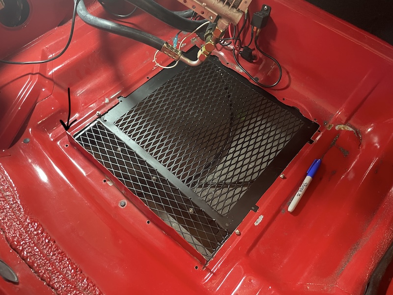 Next, after measuring the floor, I decided on a base of 17 1/2" x 17 1/2". I couldn't quite get 18" in either direction, either due to the floor pattern or the need for just a little space in the back for wiring. Using 16 gauge sheet metal, I started to work making bends for the sides, and front and back sections. I bent the metal so the retaining nuts or screws would be exposed for "easy access" in the future. I can't tell you how much of a PIA the old condenser box was. These next photos show the process of building the base and the custom top. You may notice with the picture from below the box that my plan was to mount the fan below condenser as a "puller". Note: I later, after fitment, lowered the tabs that retained the condenser down 5/8 of an inch. This prevented the need to cut into the box's top to clear the input/output connection on the condenser. The fan is a 12" 2300 rpm puller, which should do much better than the old unit. 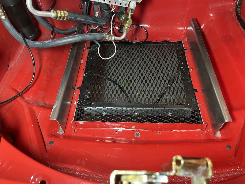 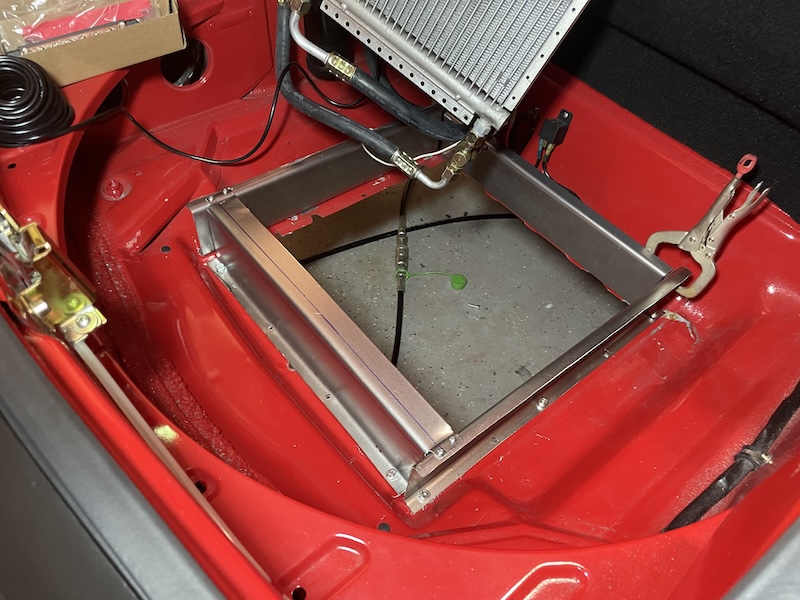 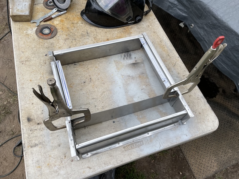 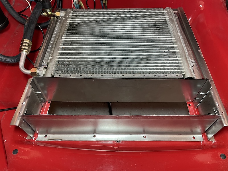 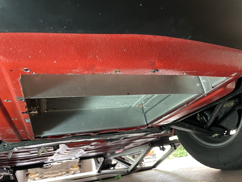 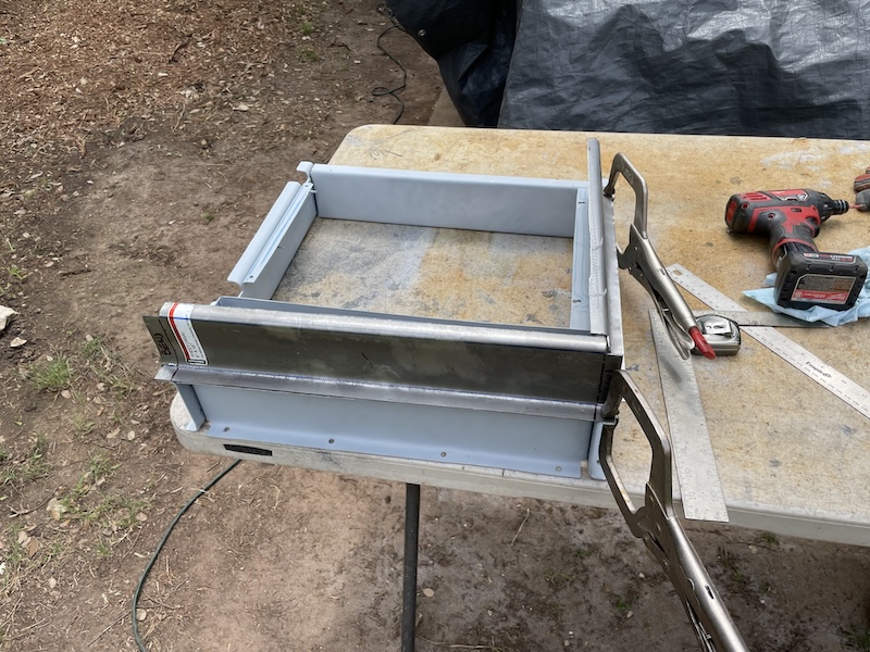 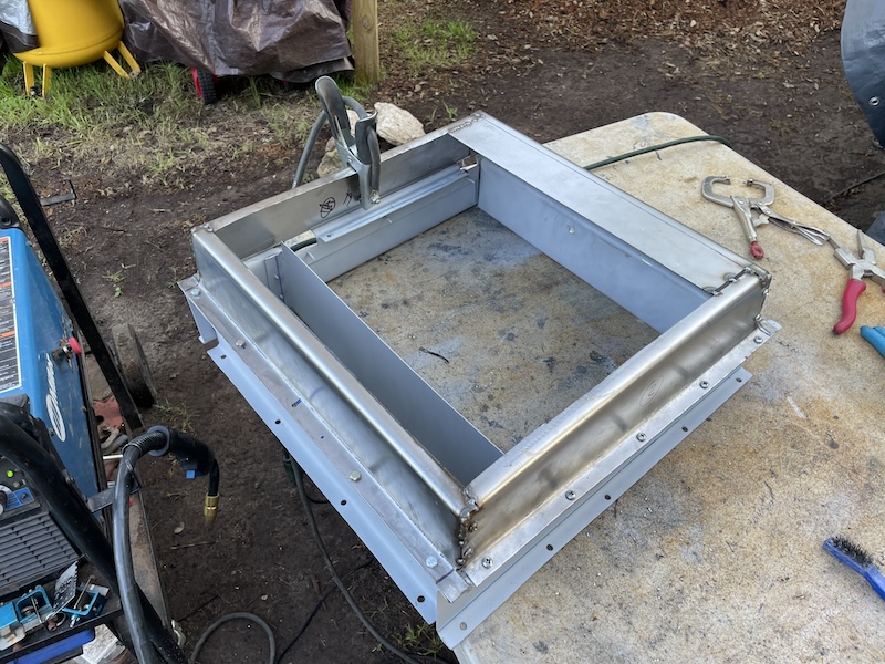 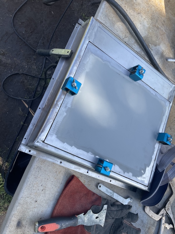 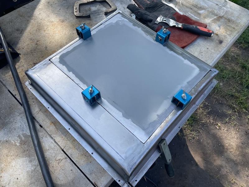 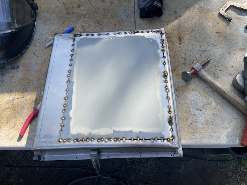 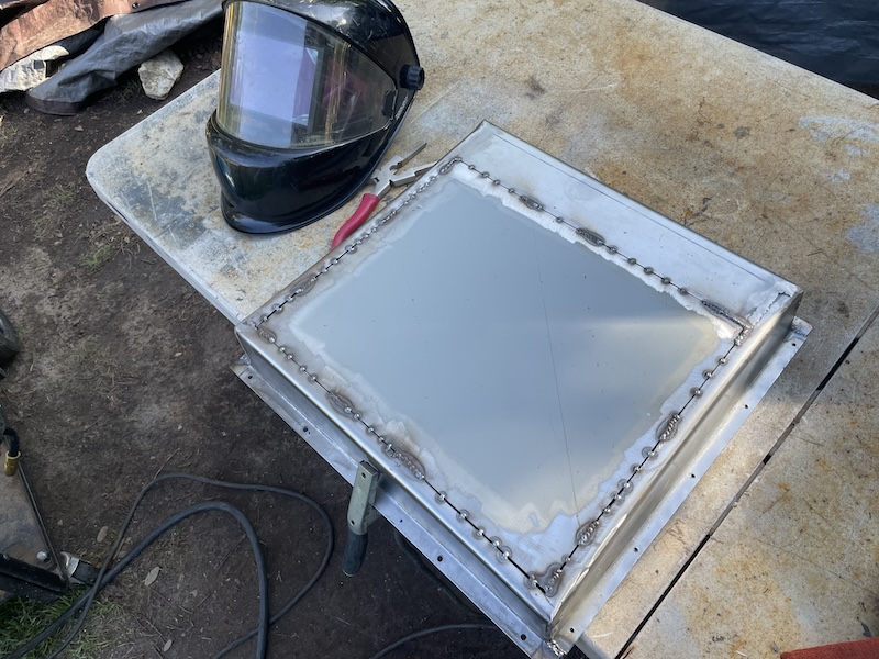 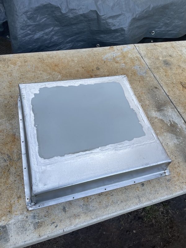 Final assembly, after a few hardware store runs to pick-up new nuts/bolts (mostly metric), I was able to install the base with seals on the bottom and the top to make the box "mostly" air-tight. You notice the positive and negative busbars that I installed behind the condenser. I already had two 10 gauge power wires coming in (one fro the compressor, the other for the fan). The busbar certainly made the [re]wiring job a lot easier. 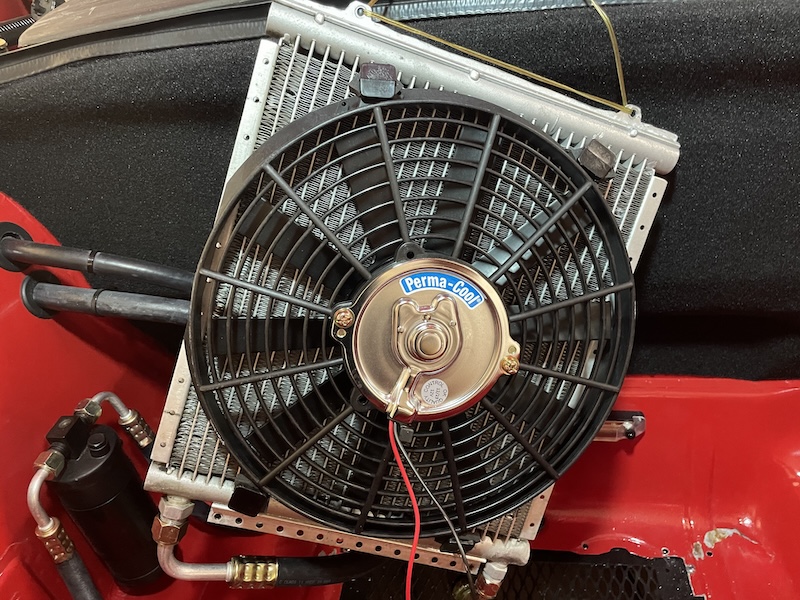 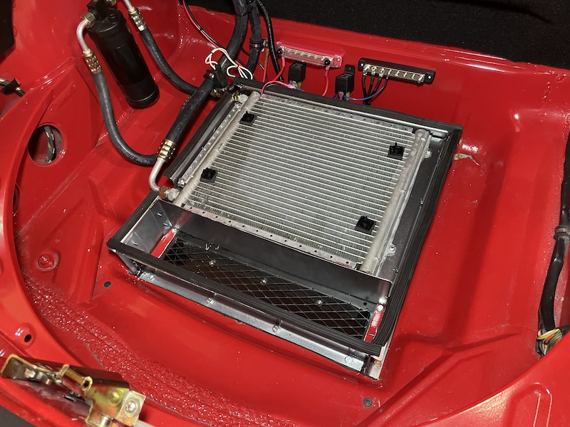 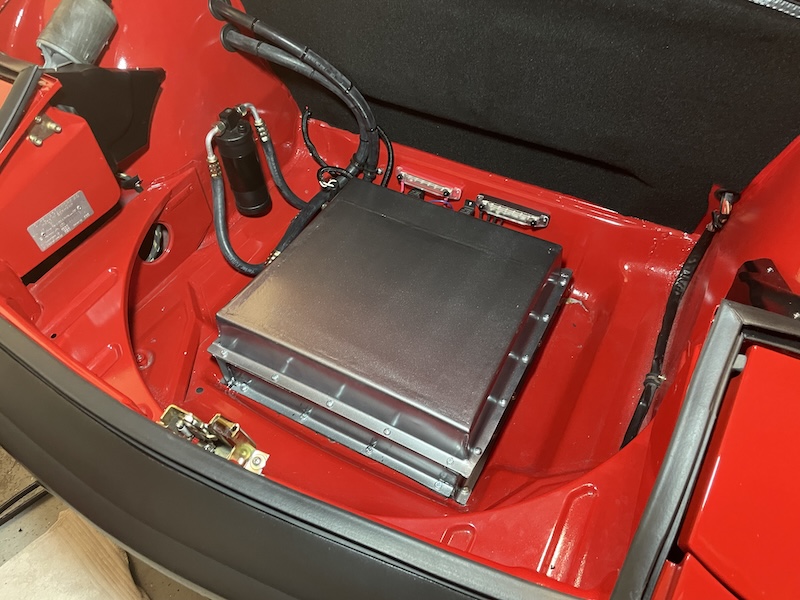 I went on a test run last night. The air coming out of the vents was noticeable colder than before. I'll try and get some numbers and figure out how to get my new A/C tester hoses hooked up this weekend. I'll report back later. |
| technicalninja |
 May 3 2024, 02:17 PM May 3 2024, 02:17 PM
Post
#190
|
|
Advanced Member     Group: Members Posts: 2,123 Joined: 31-January 23 From: Granbury Texas Member No.: 27,135 Region Association: Southwest Region 
|
Looks like you did that WITHOUT evac-ing the system!
Hat's off to you, Sir! Nicely done! I still think it's too small but what you did should be an improvement! |
| friethmiller |
 May 3 2024, 02:34 PM May 3 2024, 02:34 PM
Post
#191
|
|
Senior Member    Group: Members Posts: 667 Joined: 10-February 19 From: Austin, TX Member No.: 22,863 Region Association: Southwest Region 
|
Looks like you did that WITHOUT evac-ing the system! Hat's off to you, Sir! Nicely done! I still think it's too small but what you did should be an improvement! Correct! Thanks! I totally agree. Still not 100% sure I want to cut the front of my car and was looking for some more time to decide. (IMG:style_emoticons/default/biggrin.gif) I have no issue with the fiberglass valance. It's the front panel behind that I'm having issues with. Now that I can easy get back into this box, do you think I should add the pusher back? Or, is it better just having the condenser open to the air that's getting pulled through? The amount of space above the condenser used to be about a 1/2", it's now 2.5 to 3". I also found a deal on a few 4" pusher fans I can use. What about installing three 4" pushers to the top of this box - directly over the condenser? It's the computer-nerd in me (I guess) BTW, I replaced the spare with a stock-sized tire and moved it to the [back] trunk. |
| technicalninja |
 May 3 2024, 02:51 PM May 3 2024, 02:51 PM
Post
#192
|
|
Advanced Member     Group: Members Posts: 2,123 Joined: 31-January 23 From: Granbury Texas Member No.: 27,135 Region Association: Southwest Region 
|
you've got a puller under it now, correct?
I'd test that first before doing anything else. I have NEVER seen electric fans on both sides of a core. Lots of electric pushers in front and a mechanical fan behind... Most Toyota trucks are this way. |
| friethmiller |
 May 3 2024, 02:56 PM May 3 2024, 02:56 PM
Post
#193
|
|
Senior Member    Group: Members Posts: 667 Joined: 10-February 19 From: Austin, TX Member No.: 22,863 Region Association: Southwest Region 
|
you've got a puller under it now, correct? I'd test that first before doing anything else. I have NEVER seen electric fans on both sides of a core. Lots of electric pushers in front and a mechanical fan behind... Most Toyota trucks are this way. Correct, I have a 12" puller under it. |
| Chris914n6 |
 May 3 2024, 04:59 PM May 3 2024, 04:59 PM
Post
#194
|
|
Jackstands are my life.     Group: Members Posts: 3,423 Joined: 14-March 03 From: Las Vegas, NV Member No.: 431 Region Association: Southwest Region |
That design is alot closer to the 'factory' options so should work about as well. Keep in mind the cabin is small like a Miata, so it doesn't take alot of cold air in recirc mode to keep it cool.
As far as holes go, in and out should be equal or up to 20% larger on the exit. And it's not based on core area but fan area as that determines cfm. No on the tiny pusher fans. No. No. No. |
| friethmiller |
 May 3 2024, 06:48 PM May 3 2024, 06:48 PM
Post
#195
|
|
Senior Member    Group: Members Posts: 667 Joined: 10-February 19 From: Austin, TX Member No.: 22,863 Region Association: Southwest Region 
|
That design is alot closer to the 'factory' options so should work about as well. Keep in mind the cabin is small like a Miata, so it doesn't take alot of cold air in recirc mode to keep it cool. As far as holes go, in and out should be equal or up to 20% larger on the exit. And it's not based on core area but fan area as that determines cfm. No on the tiny pusher fans. No. No. No. Thanks @Chris914n6! Got it! No pushers. It's about to "push" up into the 90s down here next week in Texas. Should be able to test it out. |
  |
1 User(s) are reading this topic (1 Guests and 0 Anonymous Users)
0 Members:

|
Lo-Fi Version | Time is now: 27th December 2024 - 03:26 PM |
Invision Power Board
v9.1.4 © 2024 IPS, Inc.


