|
|

|
Porsche, and the Porsche crest are registered trademarks of Dr. Ing. h.c. F. Porsche AG.
This site is not affiliated with Porsche in any way. Its only purpose is to provide an online forum for car enthusiasts. All other trademarks are property of their respective owners. |
|
|
  |
| brant |
 Nov 16 2004, 06:06 PM Nov 16 2004, 06:06 PM
Post
#101
|
|
914 Wizard           Group: Members Posts: 11,926 Joined: 30-December 02 From: Colorado Member No.: 47 Region Association: Rocky Mountains 

|
couple more shots. I just wanted to document this for myself really... I painted it to look more pseudo-6.
It also has my cannabilized strut tops from my old -4 racecar: (ohhhh.. the -4 vin doesn't do much for making it look like a -6, does it) This post has been edited by brant: Nov 16 2004, 06:08 PM Attached thumbnail(s) 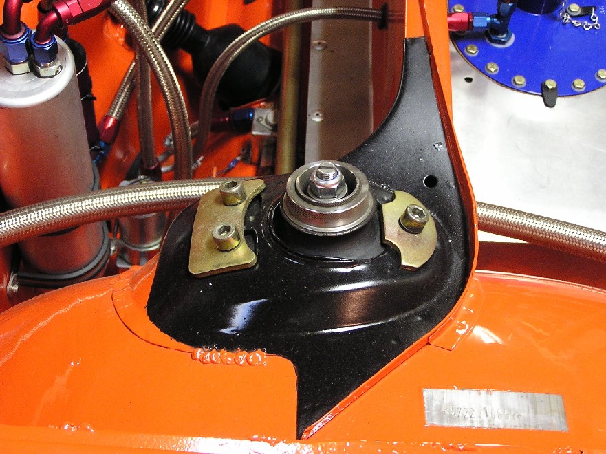
|
| ematulac |
 Nov 16 2004, 06:11 PM Nov 16 2004, 06:11 PM
Post
#102
|
|
914 addict    Group: Members Posts: 540 Joined: 24-November 03 From: Palmdale, CA Member No.: 1,382 |
(IMG:style_emoticons/default/smilie_pokal.gif) Awesome work, Brant! keep the updates and the pics coming!
|
| brant |
 Nov 16 2004, 06:13 PM Nov 16 2004, 06:13 PM
Post
#103
|
|
914 Wizard           Group: Members Posts: 11,926 Joined: 30-December 02 From: Colorado Member No.: 47 Region Association: Rocky Mountains 

|
I'm proud of this one. Here is the throttle linkage mount we made. I stole the idea from Mike Ferguson's conversion. We made it from alloy though....
The bell crank itself is not in this shot unfortunately, but you can see the mount. Also in this shot is a bit of the speedo drive. Again for a tiny bit of weight; we took the stock drive apart and removed the gear. AJ then tig'd the alloy housing to seal it up. We then reinstalled the alloy housing with the o-ring, and put a plastic cap over the hole for dirt: Attached thumbnail(s) 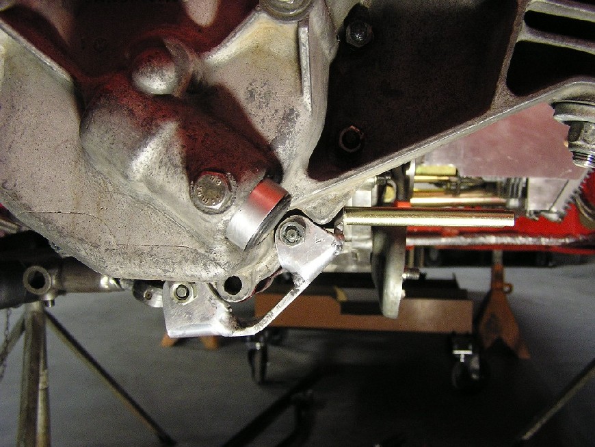
|
| brant |
 Nov 16 2004, 06:16 PM Nov 16 2004, 06:16 PM
Post
#104
|
|
914 Wizard           Group: Members Posts: 11,926 Joined: 30-December 02 From: Colorado Member No.: 47 Region Association: Rocky Mountains 

|
Ok, this one is for scott schroeder... (Scott thanks for the extra engine lid screen, here it is)
I have built a GT style lid previously on my -4 racecar. So from that experiment, plus incorporating a few items from tech articles, here is the lid for this car: Attached thumbnail(s) 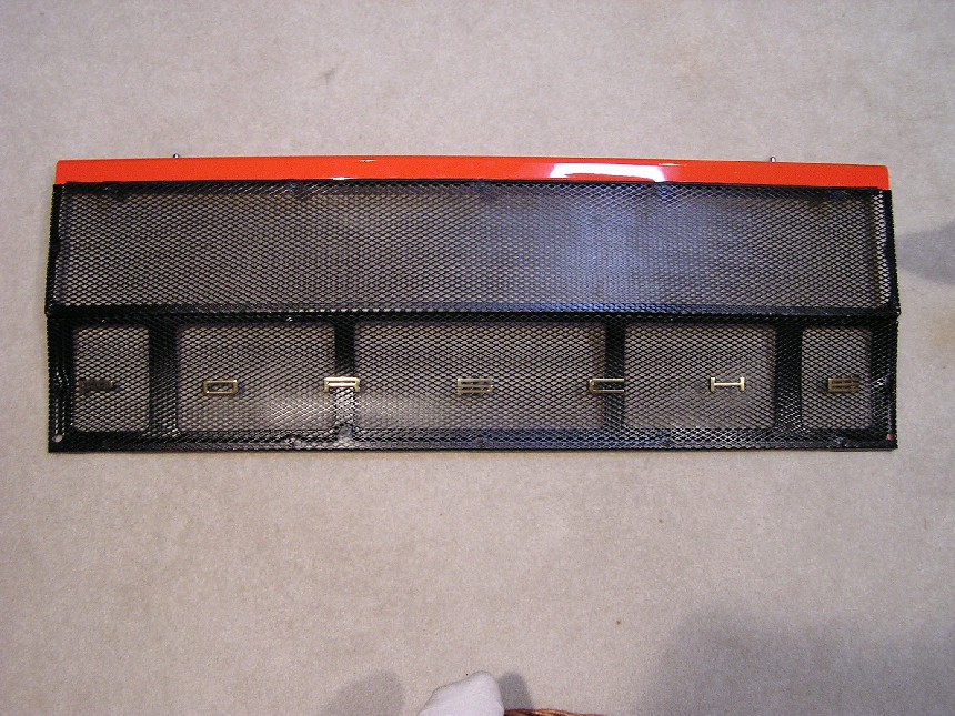
|
| brant |
 Nov 16 2004, 06:17 PM Nov 16 2004, 06:17 PM
Post
#105
|
|
914 Wizard           Group: Members Posts: 11,926 Joined: 30-December 02 From: Colorado Member No.: 47 Region Association: Rocky Mountains 

|
here is a closer one (not full view) of the underside:
Attached thumbnail(s) 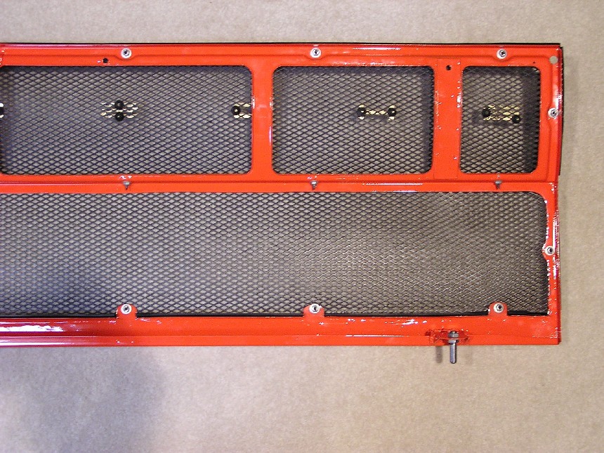
|
| brant |
 Nov 16 2004, 06:18 PM Nov 16 2004, 06:18 PM
Post
#106
|
|
914 Wizard           Group: Members Posts: 11,926 Joined: 30-December 02 From: Colorado Member No.: 47 Region Association: Rocky Mountains 

|
earlier in the thread I mentioned that the mounts for this lid poke into the cavity of the firewall. Here is a better view of how the forward edge of my lid mounts:
Attached thumbnail(s) 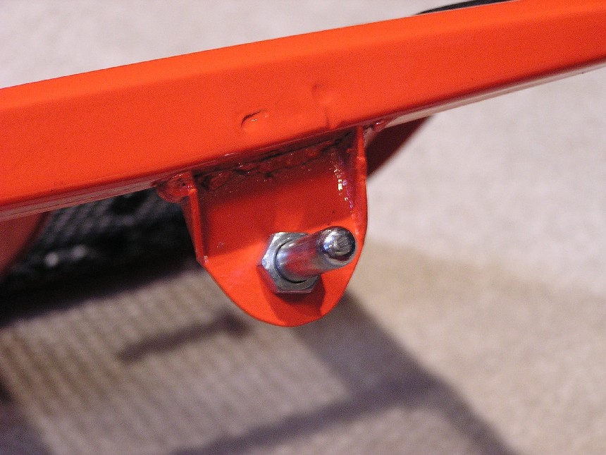
|
| brant |
 Nov 16 2004, 06:19 PM Nov 16 2004, 06:19 PM
Post
#107
|
|
914 Wizard           Group: Members Posts: 11,926 Joined: 30-December 02 From: Colorado Member No.: 47 Region Association: Rocky Mountains 

|
don't make fun of my welds now....
but here is the back side of the same mount: Attached thumbnail(s) 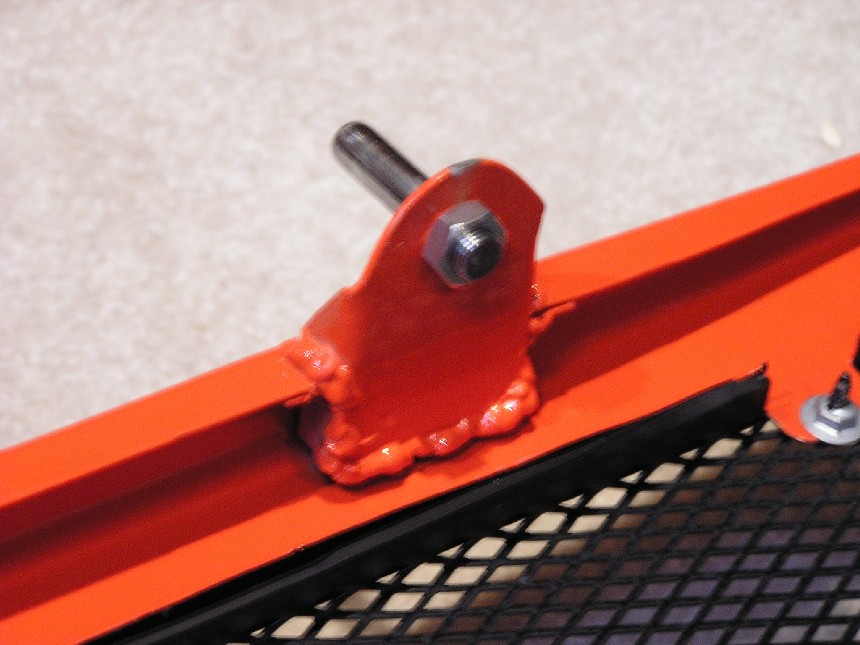
|
| brant |
 Nov 16 2004, 06:37 PM Nov 16 2004, 06:37 PM
Post
#108
|
|
914 Wizard           Group: Members Posts: 11,926 Joined: 30-December 02 From: Colorado Member No.: 47 Region Association: Rocky Mountains 

|
I haven't assembled all the bits of my rear suspension yet, but here is a trailer.
Ohh... another thanks to John Lush is in order. (John, here is the reason I had to borrow those rear cups. There in the mail back to you as we speak) I'm using a toe adjustment rod on the outboard of the rear suspension. Purpose is to lock in the toe adjustment, and rule out any changes happening in the corners. Here is the rear suspension cup: Attached thumbnail(s) 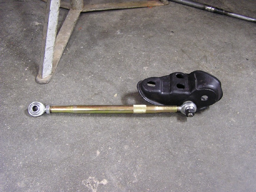
|
| brant |
 Nov 16 2004, 06:37 PM Nov 16 2004, 06:37 PM
Post
#109
|
|
914 Wizard           Group: Members Posts: 11,926 Joined: 30-December 02 From: Colorado Member No.: 47 Region Association: Rocky Mountains 

|
Another of the back side of the cup:
Attached thumbnail(s) 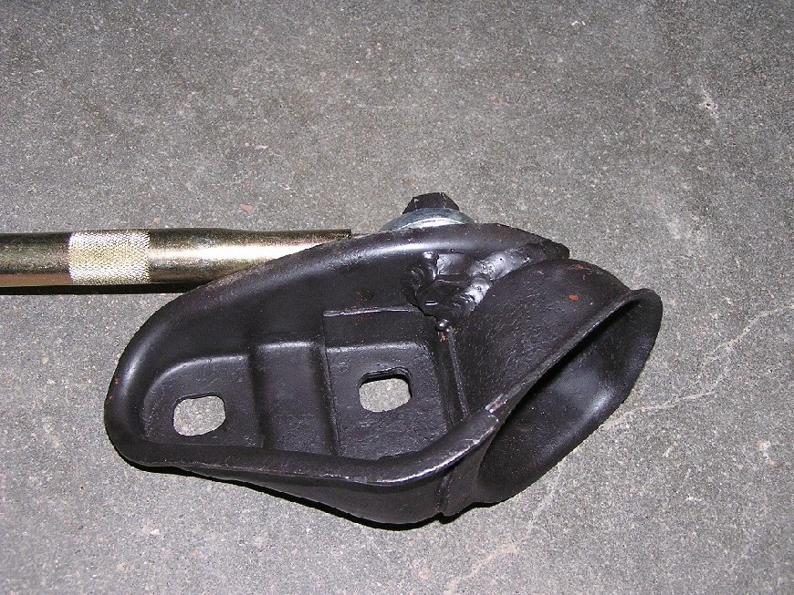
|
| brant |
 Nov 16 2004, 06:39 PM Nov 16 2004, 06:39 PM
Post
#110
|
|
914 Wizard           Group: Members Posts: 11,926 Joined: 30-December 02 From: Colorado Member No.: 47 Region Association: Rocky Mountains 

|
Previously in this thread I mentioned the weird/mounts in my longs. Here is a better picture. The toe braces run forward and mount to the long.
The mounting point consists of a threaded tube that actually runs all the way through the long. It also ties in the inboard and out board sides of the long. (In some of the engine bay pictures you can see a tiny bit of the inboard view) Here is the outboard view: Attached thumbnail(s) 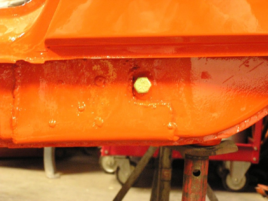
|
| Aaron Cox |
 Nov 16 2004, 06:48 PM Nov 16 2004, 06:48 PM
Post
#111
|
|
Professional Lawn Dart                Group: Retired Admin Posts: 24,541 Joined: 1-February 03 From: Corona, CA Member No.: 219 Region Association: Southern California |
no washer on the long mount for toe?
|
| brant |
 Nov 16 2004, 06:51 PM Nov 16 2004, 06:51 PM
Post
#112
|
|
914 Wizard           Group: Members Posts: 11,926 Joined: 30-December 02 From: Colorado Member No.: 47 Region Association: Rocky Mountains 

|
QUOTE(Aaron Cox @ Nov 16 2004, 05:48 PM) no washer on the long mount for toe? Don't have it actually bolted together yet.. don't think a washer will be necessary, but will see when I get the rear suspension bolted on. brant |
| brant |
 Nov 17 2004, 01:10 PM Nov 17 2004, 01:10 PM
Post
#113
|
|
914 Wizard           Group: Members Posts: 11,926 Joined: 30-December 02 From: Colorado Member No.: 47 Region Association: Rocky Mountains 

|
JP... I'll be able to add more later or tomorrow, but here is an overall view of the rear suspension console brace.
earlier in this thread I showed the attatchment points for this brace bar. And here is one with the bar installed. On my -4 race car, I ripped out 2 rear suspension consoles. Neither of them were rusty AT ALL. It was during the install of the 3rd console around 1994 that AJ educated me to the need for a brace. I ran his early version of brace for somewhere around 10 years on my -4 race car with no problems. Here is the current version: Attached thumbnail(s) 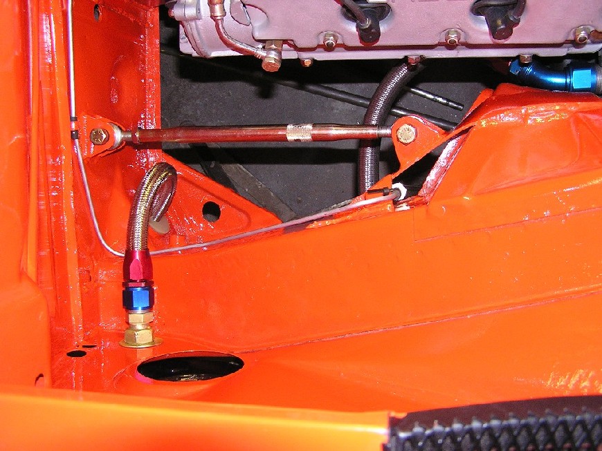
|
| brant |
 Nov 17 2004, 01:48 PM Nov 17 2004, 01:48 PM
Post
#114
|
|
914 Wizard           Group: Members Posts: 11,926 Joined: 30-December 02 From: Colorado Member No.: 47 Region Association: Rocky Mountains 

|
JP,
I know that these were fuzzy and hard to make out earlier in the thread. Here are a couple of close ups you asked for. To be perfectly honest, if I was doing this car over this is about the only area I would clean up/do differently. The problem is that this mounting point was welded in before we had finished removing the -4 mounts... If I had it to do over it would be cleaner. Still I think its strong enough and should work fine. Here is one shot: Attached thumbnail(s) 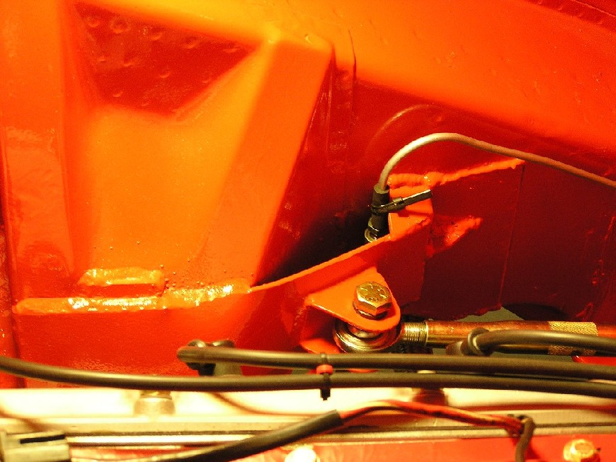
|
| brant |
 Nov 17 2004, 01:49 PM Nov 17 2004, 01:49 PM
Post
#115
|
|
914 Wizard           Group: Members Posts: 11,926 Joined: 30-December 02 From: Colorado Member No.: 47 Region Association: Rocky Mountains 

|
Here is a 2nd shot, slightly closer angle:
Attached thumbnail(s) 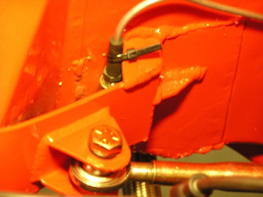
|
| brant |
 Nov 17 2004, 01:53 PM Nov 17 2004, 01:53 PM
Post
#116
|
|
914 Wizard           Group: Members Posts: 11,926 Joined: 30-December 02 From: Colorado Member No.: 47 Region Association: Rocky Mountains 

|
Where this brace attatches to the mounting nut of the swing arm... AJ welds an updown strip of metal into the cavity in the center of the mounting nut. Then overlaps it with this brace. I drew a picture because its kinda hard to explain. The new metal are the 2 pieces in red:
Attached thumbnail(s) 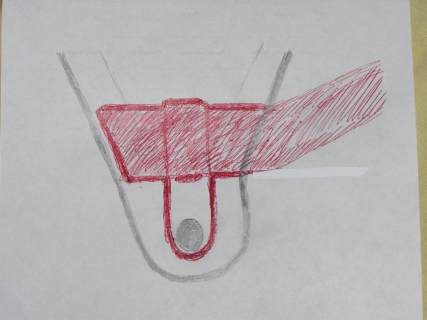
|
| brant |
 Nov 17 2004, 01:55 PM Nov 17 2004, 01:55 PM
Post
#117
|
|
914 Wizard           Group: Members Posts: 11,926 Joined: 30-December 02 From: Colorado Member No.: 47 Region Association: Rocky Mountains 

|
Here is a photo of it.
(This is from the opposite side of the car so its confusing in that it looks backwards): Attached thumbnail(s) 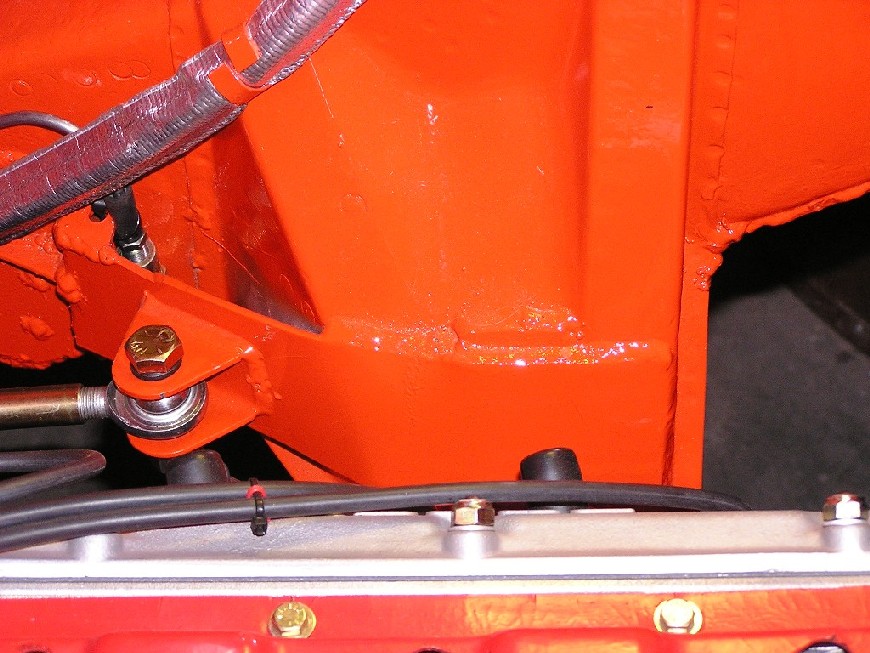
|
| J P Stein |
 Nov 17 2004, 02:50 PM Nov 17 2004, 02:50 PM
Post
#118
|
|
Irrelevant old fart      Group: Members Posts: 8,797 Joined: 30-December 02 From: Vancouver, WA Member No.: 45 Region Association: None |
Thanks, Brant.
I'm hoping to get one more season out of my ears (IMG:style_emoticons/default/laugh.gif) .....and my motor. (IMG:style_emoticons/default/huh.gif) I like what you've done, but a question (or 2). Why the tie rod type brace? Wouldn't a welded in tube have done the same the same job? Is there a big freakin gusset/doubler at the firewall end under the mounting clevis? Mine are holding up. (crossed fingers smiley here) I seamed welded them on the outer perimeter (amongst other spots) then ground the welds smooth ...leaving the crown of the welds. I like your reinforcing piece around the hole. The hole and the spot welds would seem the be the spots where cracks start. |
| brant |
 Nov 17 2004, 03:40 PM Nov 17 2004, 03:40 PM
Post
#119
|
|
914 Wizard           Group: Members Posts: 11,926 Joined: 30-December 02 From: Colorado Member No.: 47 Region Association: Rocky Mountains 

|
QUOTE(J P Stein @ Nov 17 2004, 01:50 PM) Thanks, Brant. I'm hoping to get one more season out of my ears (IMG:style_emoticons/default/laugh.gif) .....and my motor. (IMG:style_emoticons/default/huh.gif) I like what you've done, but a question (or 2). Why the tie rod type brace? Wouldn't a welded in tube have done the same the same job? Is there a big freakin gusset/doubler at the firewall end under the mounting clevis? Mine are holding up. (crossed fingers smiley here) I seamed welded them on the outer perimeter (amongst other spots) then ground the welds smooth ...leaving the crown of the welds. I like your reinforcing piece around the hole. The hole and the spot welds would seem the be the spots where cracks start. Tie rod braces instead of weld in: 2 reasons for me. 1) I'm not allowed to do weld in 2) it gets crowded in there and its nice to have them removeable (especially on a 4 cylinder as, my 4cylinder had them much more angled and the motor would have hit them during motor drops without unbolting them first) Mounting Clevis at firewall end: nope. On the 4 cylinder the brace was angled to the natural and strong indent... but hopefully strenght won't be an issue on this one because it is not doubled... brant |
| brant |
 Dec 6 2004, 09:28 PM Dec 6 2004, 09:28 PM
Post
#120
|
|
914 Wizard           Group: Members Posts: 11,926 Joined: 30-December 02 From: Colorado Member No.: 47 Region Association: Rocky Mountains 

|
couple more shots.
here is a better view(s) of what we made up for a throttle bellcrank. Had to change the angles to work on this rear-ward location: Attached thumbnail(s) 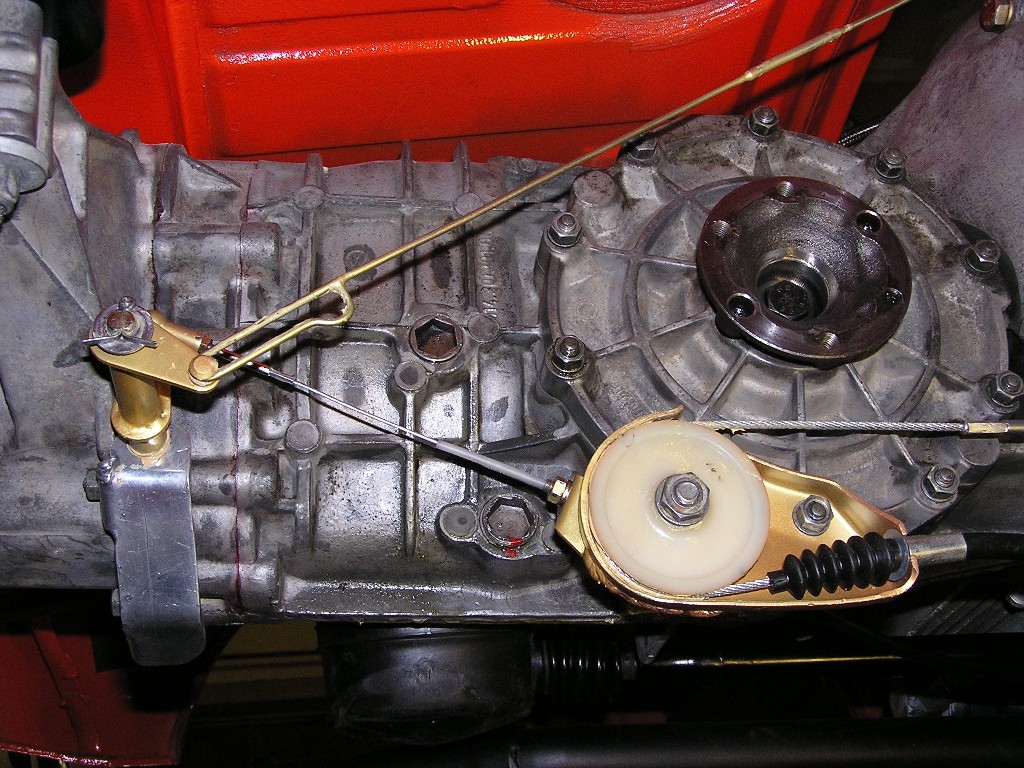
|
  |
1 User(s) are reading this topic (1 Guests and 0 Anonymous Users)
0 Members:

|
Lo-Fi Version | Time is now: 3rd April 2025 - 06:06 PM |
Invision Power Board
v9.1.4 © 2025 IPS, Inc.


