|
|
|
Porsche, and the Porsche crest are registered trademarks of Dr. Ing. h.c. F. Porsche AG.
This site is not affiliated with Porsche in any way. Its only purpose is to provide an online forum for car enthusiasts. All other trademarks are property of their respective owners. |
|
|

  |

| zymurgist |
 Nov 28 2013, 07:43 AM Nov 28 2013, 07:43 AM
Post
#141
|
|
"Ace" Mechanic  Group: Members Posts: 7,411 Joined: 9-June 05 From: Hagerstown, MD Member No.: 4,238 Region Association: None |
Great to hear of your progress. (IMG:style_emoticons/default/beerchug.gif)
|
   |

 
|
| Cairo94507 |
Nov 28 2013, 08:05 AM
Post
#142
|
|
Michael Group: Members Posts: 10,165 Joined: 1-November 08 From: Auburn, CA Member No.: 9,712 Region Association: Northern California |
Excellent work. Nice to see this project coming together.
I see you are going to use orange LED's for the turn signals, if by chance I wanted to stay with the US taillight configuration could they all be red? Is there a way to make the turn signal dual colors (switchable) if one wanted to go from euro to US and back? I know….but I thought I would ask. Happy Thanksgiving. |
|
|
|
| AndyB |
Nov 28 2013, 08:49 AM
Post
#143
|
|
The Governor is watching me Group: Members Posts: 1,115 Joined: 10-April 10 From: Philadelphia New York Member No.: 11,595 Region Association: North East States |
QUOTE(cpavlenko @ Nov 26 2013, 12:51 AM)  check this out. >>>>>>. http://www.superbrightleds.com/cat/led-veh...rsche---/49---/ they even have the relay for the led lights. I'm thinking... Those are what I have in mine right now. I also have a FLAPS third brake light mounted so that you wont notice it until its on. Although I dont have all my resistors in place yet, the turn signals still flash I just don't get the flashing green light on my dash. Just my $.02 |
|
|
|
| Spoke |
Nov 30 2013, 03:21 PM
Post
#144
|
|
Jerry Group: Members Posts: 7,113 Joined: 29-October 04 From: Allentown, PA Member No.: 3,031 Region Association: None |
QUOTE(Cairo94507 @ Nov 28 2013, 09:05 AM) Excellent work. Nice to see this project coming together. I see you are going to use orange LED's for the turn signals, if by chance I wanted to stay with the US taillight configuration could they all be red? Is there a way to make the turn signal dual colors (switchable) if one wanted to go from euro to US and back? I know….but I thought I would ask. Happy Thanksgiving. The high power LEDs I am using are from Cree and come in white, amber, red, red-orange, and blue. Red LEDs can be substituted for amber. Switchable usually have 2 or more LEDs mounted in a single package with either 2 or 3 connections. Not planning to do any switching at this point. I made about 100 changes to the PCB over the weekend. The plan now is to order the boards for the brake/taillights next week. All the parts are available on Digikey but I'm going to go through my contact at Arrow for better pricing. Still trying to figure out how to connect to the existing brake light socket. I want something like a bulb base with wires going to the PCB to plug into the existing taillight fixture. If I have to I will cannibalize a couple of bulbs and add wires to them to connect the PCB. I want to make as little modifications to the taillight fixture as possible and be able to return to the bulb if I need to work on the PCB. (Don't want to take the 914 out of service because of the PCB). Attached image(s) 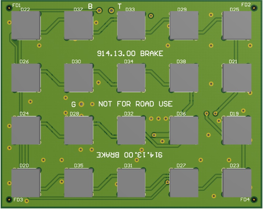 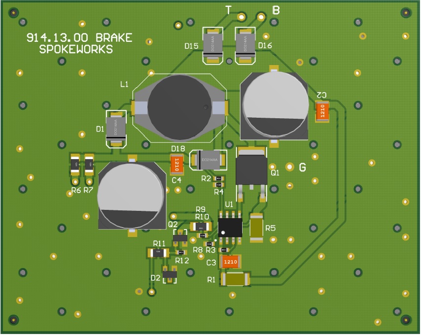
|
|
|
|
| timothy_nd28 |
Nov 30 2013, 03:38 PM
Post
#145
|
|
Advanced Member Group: Members Posts: 2,299 Joined: 25-September 07 From: IN Member No.: 8,154 Region Association: Upper MidWest |
Looks awesome! Digikey charges sales tax and I found them to be a tad more expensive. Check out mouser.
|
|
|
|
| mikesmith |
Nov 30 2013, 03:41 PM
Post
#146
|
|
Member Group: Members Posts: 202 Joined: 5-September 13 From: SF Member No.: 16,354 Region Association: Northern California |
You may be better off using yellow for amber. Certainly, I've tried red LEDs in amber tinted housings and been less than happy with the results. The yellow LEDs are pretty shockingly yellow, but they are very attention-getting...
|
|
|
|
| McMark |
Nov 30 2013, 07:06 PM
Post
#147
|
|
914 Freak! Group: Retired Admin Posts: 20,179 Joined: 13-March 03 From: Grand Rapids, MI Member No.: 419 Region Association: None |
If you want a spare set of taillight housings, just ask.
|
|
|
|
| Spoke |
Dec 1 2013, 01:29 AM
Post
#148
|
|
Jerry Group: Members Posts: 7,113 Joined: 29-October 04 From: Allentown, PA Member No.: 3,031 Region Association: None |
QUOTE(McMark @ Nov 30 2013, 08:06 PM) If you want a spare set of taillight housings, just ask. Thanks Mark, I think I'm good now. I will use my 914 as the test bed for these units. Mounting holes were added for #6 screws and the corners trimmed to fit deeper in the housing. 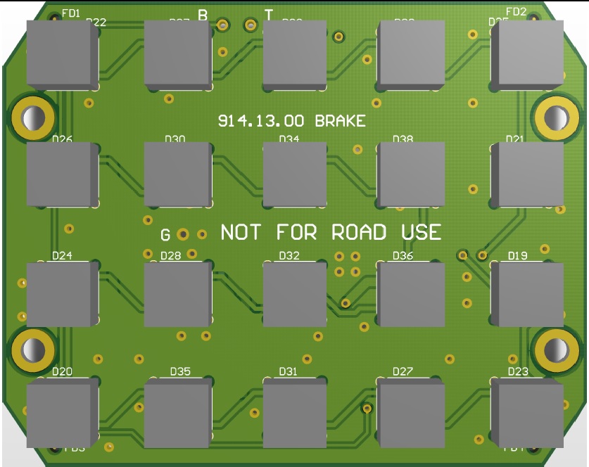 Still trying to figure out how to power this unit with minimally invasive techniques. This is just the guts of an 1157 bulb with wires soldered to the filament leads. Solder the wires to the board and plug the base into the socket for power. 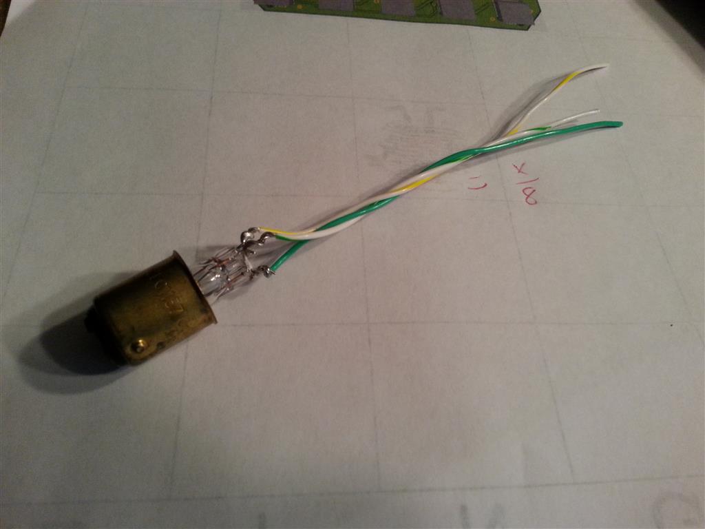 |
|
|
|
| mikesmith |
Dec 1 2013, 01:35 AM
Post
#149
|
|
Member Group: Members Posts: 202 Joined: 5-September 13 From: SF Member No.: 16,354 Region Association: Northern California |
You can get bayonet to wire adapters from the usual suspects, but honestly the bayonets are one of the weakest points in the original design. The wires from the back housing have spade connectors on them - better to solder lugs to the back of the PCB, or use flying leads if you are retaining the reflectors and just snake out through the fittings.
In my case, at least, the unsupported wires are fraying off the riveted crimps, so an option to refurb and solder direct to the brass crimps might also be worthwhile. |
|
|
|
| Harpo |
Dec 1 2013, 06:24 AM
Post
#150
|
|
Senior Member Group: Members Posts: 1,304 Joined: 21-August 11 From: Motor City aka Detroit Member No.: 13,469 Region Association: None |
Glad to see more progress on this project. Keep up the good work.
Thanks David |
|
|
|
| Spoke |
Dec 1 2013, 09:38 AM
Post
#151
|
|
Jerry Group: Members Posts: 7,113 Joined: 29-October 04 From: Allentown, PA Member No.: 3,031 Region Association: None |
QUOTE(mikesmith @ Dec 1 2013, 02:35 AM) You can get bayonet to wire adapters from the usual suspects, but honestly the bayonets are one of the weakest points in the original design. The wires from the back housing have spade connectors on them - better to solder lugs to the back of the PCB, or use flying leads if you are retaining the reflectors and just snake out through the fittings. In my case, at least, the unsupported wires are fraying off the riveted crimps, so an option to refurb and solder direct to the brass crimps might also be worthwhile. Could you point to one of the usual suspects who carries bayonet wire adapters? I haven't had any luck searching for them. Agreed the bayonets are a weak point. At this point, I'm trying to be minimally invasive to the light housing. This would also make it easy for others to connect theirs. A PCB connector and direct wiring could be in the future. |
|
|
|
| Spoke |
Dec 1 2013, 09:54 AM
Post
#152
|
|
Jerry Group: Members Posts: 7,113 Joined: 29-October 04 From: Allentown, PA Member No.: 3,031 Region Association: None |
|
|
|
|
| Spoke |
Dec 1 2013, 09:54 AM
Post
#153
|
|
Jerry Group: Members Posts: 7,113 Joined: 29-October 04 From: Allentown, PA Member No.: 3,031 Region Association: None |
Attached image(s) 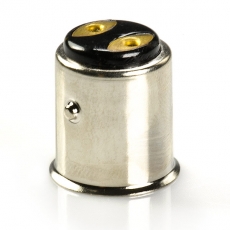
|
|
|
|
| Spoke |
Dec 1 2013, 09:54 AM
Post
#154
|
|
Jerry Group: Members Posts: 7,113 Joined: 29-October 04 From: Allentown, PA Member No.: 3,031 Region Association: None |
|
|
|
|
| Spoke |
Dec 1 2013, 10:05 AM
Post
#155
|
|
Jerry Group: Members Posts: 7,113 Joined: 29-October 04 From: Allentown, PA Member No.: 3,031 Region Association: None |
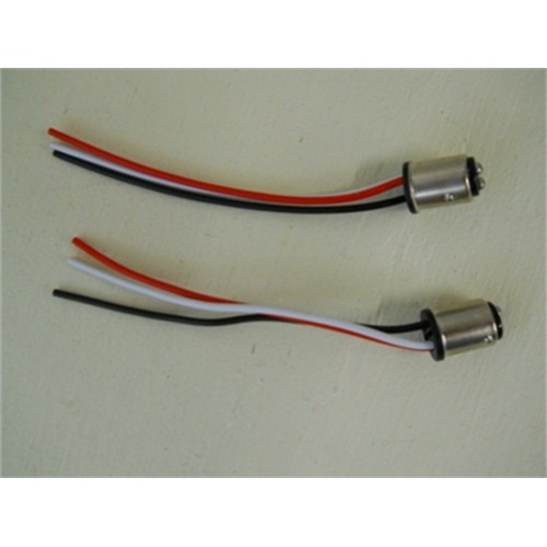
Found this one. A bit expensive at 8.95 Euro.
Attached image(s) 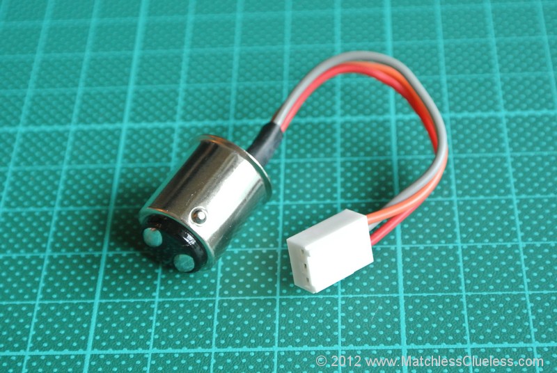
|
|
|
|
| Spoke |
Dec 1 2013, 10:15 AM
Post
#156
|
|
Jerry Group: Members Posts: 7,113 Joined: 29-October 04 From: Allentown, PA Member No.: 3,031 Region Association: None |
|
|
|
|
| McMark |
Dec 1 2013, 02:26 PM
Post
#157
|
|
914 Freak! Group: Retired Admin Posts: 20,179 Joined: 13-March 03 From: Grand Rapids, MI Member No.: 419 Region Association: None |
So is this board going to sit inside the 'chrome' reflector? That piece comes out with just two screws. Why not pull the whole thing and make a board that uses those two screws to mount? Plus behind the chrome piece are lengths of wire you can tap directly into. Add spade connectors and you've got an interchangeable piece if you need to swap back... (IMG:style_emoticons/default/idea.gif)
|
|
|
|
| gothspeed |
Dec 1 2013, 02:42 PM
Post
#158
|
|
Senior Member Group: Members Posts: 1,539 Joined: 3-February 09 From: SoCal Member No.: 10,019 Region Association: None |
QUOTE(McMark @ Dec 1 2013, 12:26 PM) So is this board going to sit inside the 'chrome' reflector? That piece comes out with just two screws. Why not pull the whole thing and make a board that uses those two screws to mount? Plus behind the chrome piece are lengths of wire you can tap directly into. Add spade connectors and you've got an interchangeable piece if you need to swap back... (IMG:style_emoticons/default/idea.gif) +1 ....... (IMG:style_emoticons/default/popcorn[1].gif) |
|
|
|
| mikesmith |
Dec 1 2013, 03:57 PM
Post
#159
|
|
Member Group: Members Posts: 202 Joined: 5-September 13 From: SF Member No.: 16,354 Region Association: Northern California |
QUOTE(McMark @ Dec 1 2013, 12:26 PM) So is this board going to sit inside the 'chrome' reflector? That piece comes out with just two screws. Why not pull the whole thing and make a board that uses those two screws to mount? Plus behind the chrome piece are lengths of wire you can tap directly into. Add spade connectors and you've got an interchangeable piece if you need to swap back... (IMG:style_emoticons/default/idea.gif) What I said above. The big reason to keep the chromed plastic is that it includes the separator pieces that prevent bleed between the different coloured regions, and it gives you a frame that you can attach, single-coloured LED assemblies to. Assuming Spoke is using the (cheap, popular, efficient) 5050SMD LEDs, they tend to have a beam angle around 120°, so you can't position them very far from the diffuser before you need to deal with bleed. If you wanted to do without the separators you would have to move the LEDs much closer to the diffuser, but then you're going to have to fabricate a replacement carrier and work out how to attach it, or build a much bigger PCB and sort out how to avoid cross-bleed. If someone had a good idea for building a sheet aluminium carrier that sat ~15mm back from the diffuser (needs to be mostly flat, so only bends between colour segments) and supporting it from the stock fasteners, that would make this sort of thing much easier. This would also give you somewhere to attach some of the red reflective tape to make the clear rears more DOT-friendly. |
|
|
|
| McMark |
Dec 1 2013, 06:43 PM
Post
#160
|
|
914 Freak! Group: Retired Admin Posts: 20,179 Joined: 13-March 03 From: Grand Rapids, MI Member No.: 419 Region Association: None |
No I get it. But building separators seems like a trivial task to me, especially for testing. But I realize there's more than one way to skin a cat.
|
|
|
|
|
1 User(s) are reading this topic (1 Guests and 0 Anonymous Users)
0 Members:

|
Lo-Fi Version | Time is now: 12th January 2025 - 06:56 AM |
Invision Power Board
v9.1.4 © 2025 IPS, Inc.