|
|
|
Porsche, and the Porsche crest are registered trademarks of Dr. Ing. h.c. F. Porsche AG.
This site is not affiliated with Porsche in any way. Its only purpose is to provide an online forum for car enthusiasts. All other trademarks are property of their respective owners. |
|
|

  |

| Spoke |
 Dec 1 2013, 08:14 PM Dec 1 2013, 08:14 PM
Post
#161
|
|
Jerry  Group: Members Posts: 7,113 Joined: 29-October 04 From: Allentown, PA Member No.: 3,031 Region Association: None |
QUOTE(McMark @ Dec 1 2013, 03:26 PM)  So is this board going to sit inside the 'chrome' reflector? That piece comes out with just two screws. Why not pull the whole thing and make a board that uses those two screws to mount? Plus behind the chrome piece are lengths of wire you can tap directly into. Add spade connectors and you've got an interchangeable piece if you need to swap back... (IMG:style_emoticons/default/idea.gif) This test board will fit in between the reflector. My motivation with this small board is to get my feet on the ground regarding LED power, the LED driver and the LED lenses. Once that is figured out, then I will have more confidence to design the board shown in post #17. It is likely that there will be more than one board design. Right now it would be the small board and the larger full taillight board requiring the removal of the chrome reflector. Dividers would not be an issue and could be done with metal or even PCB material. |
   |

 
|
| Spoke |
Dec 4 2013, 02:58 PM
Post
#162
|
|
Jerry Group: Members Posts: 7,113 Joined: 29-October 04 From: Allentown, PA Member No.: 3,031 Region Association: None |
Ordered a couple of boards today.
I made a couple of more changes to the circuitry and added some side view LEDs. These LEDs would be used at the tip of the boards to illuminate the side marker. The side mounted LEDs have significantly less current rating (30ma) so it will be interesting to see how well they show up. Here's a view from the side. Altium is pretty cool as in 3d mode it allows you to go inside the board and look at the different layers, vias, and holes. You can see the holes and vias in this shot. Attached image(s) 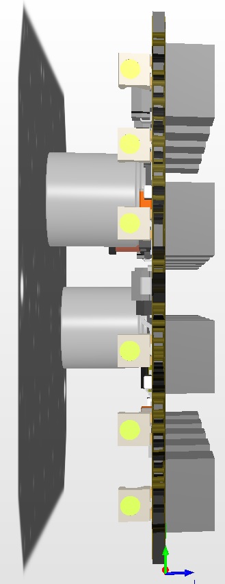
|
|
|
|
| JmuRiz |
Dec 4 2013, 03:08 PM
Post
#163
|
|
914 Guru Group: Members Posts: 5,519 Joined: 30-December 02 From: NoVA Member No.: 50 Region Association: MidAtlantic Region |
Check out these units, a lot of local 356 guys have them:
http://www.culayer.com/Porsche_356.htm I'm planning on buying a set when I save up the $$, it's nice to have bright lights, especially on tiny lenses like the 356 has. |
|
|
|
| mikesmith |
Dec 4 2013, 04:22 PM
Post
#164
|
|
Member Group: Members Posts: 202 Joined: 5-September 13 From: SF Member No.: 16,354 Region Association: Northern California |
The Classic Auto LEDs folks (http://www.classicautoleds.com) do something similar for a number of different vehicles, too.
Their approach is fairly low-tech (TH LEDs, multiple PCBs) but their BoM cost is likely to be very good. Still not as much fun as designing your own. 8) |
|
|
|
| timothy_nd28 |
Dec 4 2013, 04:25 PM
Post
#165
|
|
Advanced Member Group: Members Posts: 2,299 Joined: 25-September 07 From: IN Member No.: 8,154 Region Association: Upper MidWest |
How many vias are on the board?
|
|
|
|
| Spoke |
Dec 4 2013, 06:09 PM
Post
#166
|
|
Jerry Group: Members Posts: 7,113 Joined: 29-October 04 From: Allentown, PA Member No.: 3,031 Region Association: None |
QUOTE(JmuRiz @ Dec 4 2013, 04:08 PM) Check out these units, a lot of local 356 guys have them: http://www.culayer.com/Porsche_356.htm I'm planning on buying a set when I save up the $$, it's nice to have bright lights, especially on tiny lenses like the 356 has. QUOTE(mikesmith @ Dec 4 2013, 05:22 PM) The Classic Auto LEDs folks (http://www.classicautoleds.com) do something similar for a number of different vehicles, too. Their approach is fairly low-tech (TH LEDs, multiple PCBs) but their BoM cost is likely to be very good. Still not as much fun as designing your own. 8) These both use the through hole 5mm LEDs which are generally inexpensive. Hard to tell how they are driving them. maybe a linear regulator followed by some resistors? QUOTE(timothy_nd28 @ Dec 4 2013, 05:25 PM) How many vias are on the board? There are 61 vias on the board. Most of them connect the ground planes on the top and bottom of the board. I've covered the top and bottom with ground for thermal considerations. |
|
|
|
| mikesmith |
Dec 4 2013, 06:49 PM
Post
#167
|
|
Member Group: Members Posts: 202 Joined: 5-September 13 From: SF Member No.: 16,354 Region Association: Northern California |
QUOTE(Spoke @ Dec 4 2013, 04:09 PM) QUOTE(mikesmith @ Dec 4 2013, 05:22 PM) The Classic Auto LEDs folks (http://www.classicautoleds.com) do something similar for a number of different vehicles, too. Their approach is fairly low-tech (TH LEDs, multiple PCBs) but their BoM cost is likely to be very good. Still not as much fun as designing your own. 8) These both use the through hole 5mm LEDs which are generally inexpensive. Hard to tell how they are driving them. maybe a linear regulator followed by some resistors? I just remembered that I had a set in a box here from another stalled project, so I pulled one out to see. It looks like a simple constant current setup using a ZTX749, feeding a bunch of LED + resistor strings in parallel. For the one I measured (a turn signal) I can't say that makes me very happy. At 13.8V in and 250mA LED current, the (un-heatsinked) transistor is dropping 2.75V and it's too hot to touch after just a couple of seconds. I guess it's a good thing I'm just going to box these up and sell them off. The build quality is fine, and they're definitely bright enough, but the thermal setup on the current source is a big no. |
|
|
|
| Spoke |
Dec 6 2013, 08:50 AM
Post
#168
|
|
Jerry Group: Members Posts: 7,113 Joined: 29-October 04 From: Allentown, PA Member No.: 3,031 Region Association: None |
QUOTE(mikesmith @ Dec 4 2013, 07:49 PM) I just remembered that I had a set in a box here from another stalled project, so I pulled one out to see. It looks like a simple constant current setup using a ZTX749, feeding a bunch of LED + resistor strings in parallel. For the one I measured (a turn signal) I can't say that makes me very happy. At 13.8V in and 250mA LED current, the (un-heatsinked) transistor is dropping 2.75V and it's too hot to touch after just a couple of seconds. I guess it's a good thing I'm just going to box these up and sell them off. The build quality is fine, and they're definitely bright enough, but the thermal setup on the current source is a big no. After viewing those aftermarket 356 LED lights using common 5mm round LEDs, I decided to try one just to see how it performs. It seems they put 4 LEDs in series which would drop about 10V leaving 2.75V across the transistor. I have 21 strings of 3 LEDs in series at 40mA each string. I thought about 4 in a string but at 10V the LEDs would barely light. So the current draw on this board will be about 800ma. I kept it simple using resistors in each string to drop voltage and allow a low operating voltage and disperse the heat sources (resistors) across the board. The LEDs are manufactured by Vishay and are dirt cheap at 15 cents each. Attached image(s) 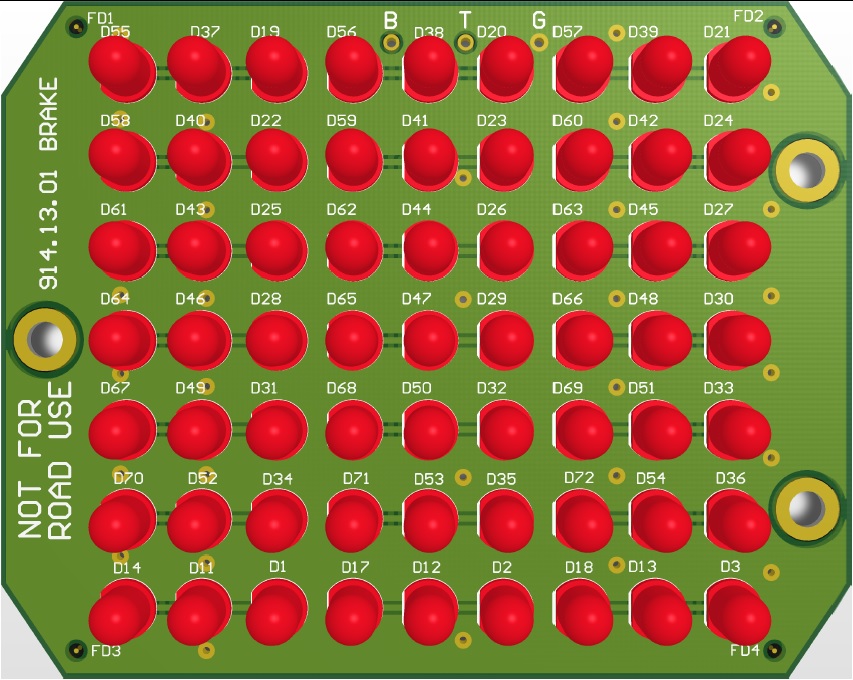
|
|
|
|
| mikesmith |
Dec 6 2013, 10:24 AM
Post
#169
|
|
Member Group: Members Posts: 202 Joined: 5-September 13 From: SF Member No.: 16,354 Region Association: Northern California |
You could also consider using an LED backlight driver like the NCS29001, and a 555 to provide the PWM dimming signal for tail vs. brake functions. That would let you run all the LEDs in a single string with very low dissipation.
(It's a new part, but you might be able to get samples from OnSemi...) |
|
|
|
| Spoke |
Dec 6 2013, 03:48 PM
Post
#170
|
|
Jerry Group: Members Posts: 7,113 Joined: 29-October 04 From: Allentown, PA Member No.: 3,031 Region Association: None |
QUOTE(mikesmith @ Dec 6 2013, 11:24 AM) You could also consider using an LED backlight driver like the NCS29001, and a 555 to provide the PWM dimming signal for tail vs. brake functions. That would let you run all the LEDs in a single string with very low dissipation. (It's a new part, but you might be able to get samples from OnSemi...) I looked at that boost switcher along with many others. Couldn't find one that suited my needs that was simple, cheap, and rugged. The NCS29001 doesn't have enough voltage capability (18V) for automotive use. I was looking for boost switchers with >36V capability to take into consideration transients on the power supply leads (brake, turnsignal, and taillight). On the other board I'm using the IS31LT3948. It's cheap and simple to use. I'm curious to see how it starts up as with turnsignals especially, it will be turning on and off on a regular basis. The datasheet suggested a 220uF cap on the input which would be charged every time the brake, turnsignal, or taillight turns on. Seems like a lot of capacitance so I will try a 22uF cap to begin with just to lower the inrush current on turn on. |
|
|
|
| Cairo94507 |
Dec 6 2013, 05:25 PM
Post
#171
|
|
Michael Group: Members Posts: 10,165 Joined: 1-November 08 From: Auburn, CA Member No.: 9,712 Region Association: Northern California |
Yeah….what he just said (IMG:style_emoticons/default/smile.gif)
Seriously, I am really looking forward to LED taillights. They are going to be so nice and increase safety by a ton. Thanks for tacking this major project. |
|
|
|
| mikesmith |
Dec 6 2013, 05:28 PM
Post
#172
|
|
Member Group: Members Posts: 202 Joined: 5-September 13 From: SF Member No.: 16,354 Region Association: Northern California |
QUOTE(Spoke @ Dec 6 2013, 01:48 PM) QUOTE(mikesmith @ Dec 6 2013, 11:24 AM) You could also consider using an LED backlight driver like the NCS29001, and a 555 to provide the PWM dimming signal for tail vs. brake functions. That would let you run all the LEDs in a single string with very low dissipation. (It's a new part, but you might be able to get samples from OnSemi...) I looked at that boost switcher along with many others. Couldn't find one that suited my needs that was simple, cheap, and rugged. The NCS29001 doesn't have enough voltage capability (18V) for automotive use. I was looking for boost switchers with >36V capability to take into consideration transients on the power supply leads (brake, turnsignal, and taillight). On the other board I'm using the IS31LT3948. It's cheap and simple to use. I'm curious to see how it starts up as with turnsignals especially, it will be turning on and off on a regular basis. The datasheet suggested a 220uF cap on the input which would be charged every time the brake, turnsignal, or taillight turns on. Seems like a lot of capacitance so I will try a 22uF cap to begin with just to lower the inrush current on turn on. 18V in conjunction with a polyswitch and a zener would probably be fine. If you are seeing 18V input on a taillight then something is pretty wrong... That ISSI part looks pretty neat, and the pricing is definitely in the right ballpark. = Mike |
|
|
|
| Spoke |
Dec 16 2013, 03:49 PM
Post
#173
|
|
Jerry Group: Members Posts: 7,113 Joined: 29-October 04 From: Allentown, PA Member No.: 3,031 Region Association: None |
Received the high power LED boards today. They look good and fit in the brake housing nicely. These boards are just to see if the circuit works as a brake and as well as a blinker.
Parts are on order and hopefully will see the parts before Christmas. Attached image(s) 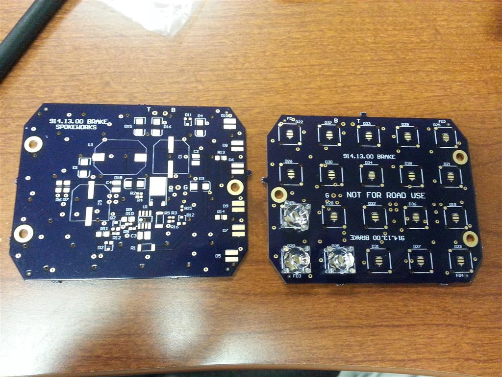 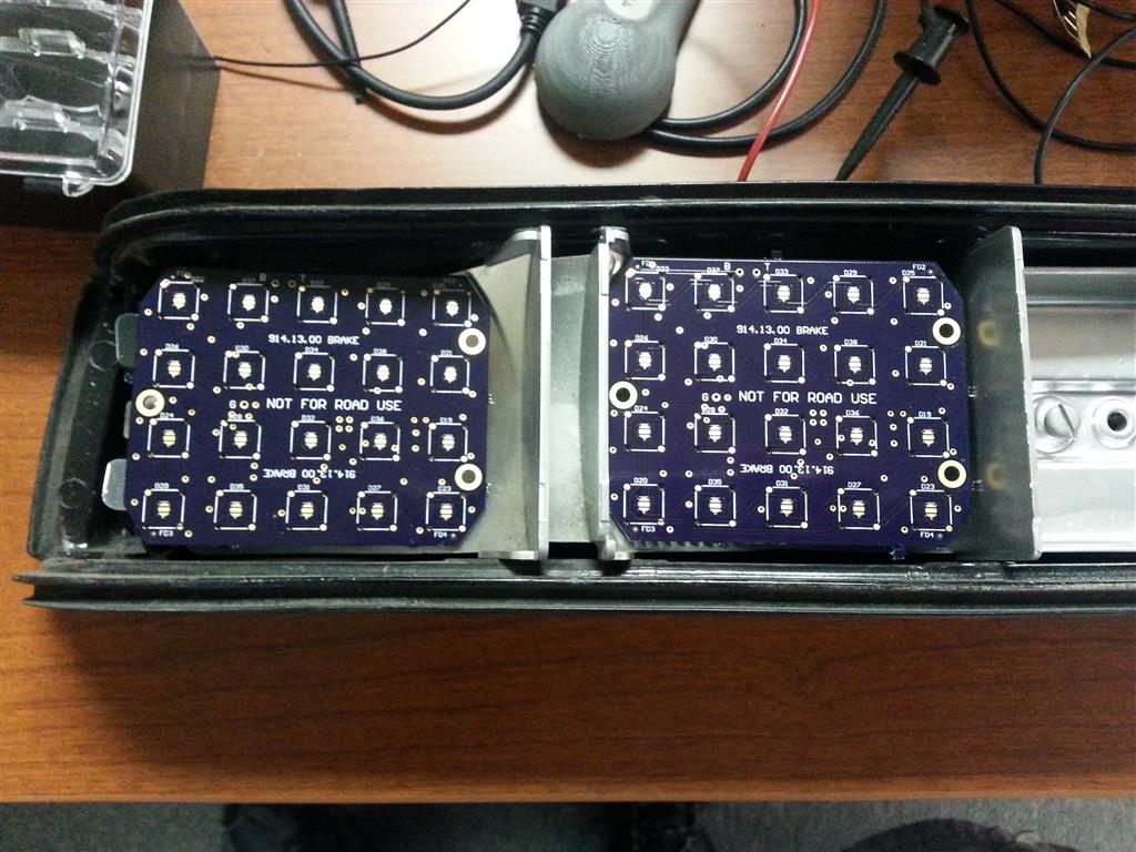
|
|
|
|
| Spoke |
Dec 16 2013, 03:51 PM
Post
#174
|
|
Jerry Group: Members Posts: 7,113 Joined: 29-October 04 From: Allentown, PA Member No.: 3,031 Region Association: None |
The lenses fit nicely in the holes provided. Opposite feet have a dimple to help align them over the LED. The lenses make all the difference in the world when trying to focus the LED light towards the rear of the car.
Attached image(s) 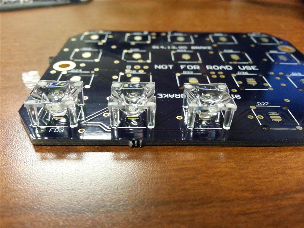
|
|
|
|
| Spoke |
Dec 16 2013, 03:52 PM
Post
#175
|
|
Jerry Group: Members Posts: 7,113 Joined: 29-October 04 From: Allentown, PA Member No.: 3,031 Region Association: None |
Also got some bulb bases so I can quickly switch in/out the LED board and existing lamps.
Attached image(s) 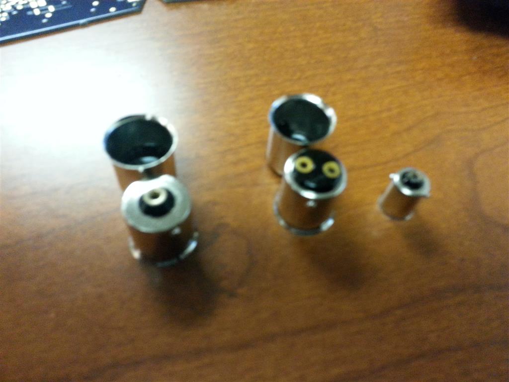
|
|
|
|
| CptTripps |
Dec 16 2013, 03:53 PM
Post
#176
|
|
:: Punch and Pie :: Group: Members Posts: 3,584 Joined: 26-December 04 From: Mentor, OH Member No.: 3,342 Region Association: Upper MidWest |
Holy shit! Those look bad-ass!
|
|
|
|
| Chris H. |
Dec 16 2013, 04:02 PM
Post
#177
|
|
Senior Member Group: Members Posts: 4,053 Joined: 2-January 03 From: Chicago 'burbs Member No.: 73 Region Association: Upper MidWest |
(IMG:style_emoticons/default/agree.gif) You're REALLY DOING THIS!!!!
|
|
|
|
| zymurgist |
Dec 16 2013, 04:14 PM
Post
#178
|
|
"Ace" Mechanic Group: Members Posts: 7,411 Joined: 9-June 05 From: Hagerstown, MD Member No.: 4,238 Region Association: None |
|
|
|
|
| Harpo |
Dec 16 2013, 06:21 PM
Post
#179
|
|
Senior Member Group: Members Posts: 1,304 Joined: 21-August 11 From: Motor City aka Detroit Member No.: 13,469 Region Association: None |
Very impressive, keep up the good work
Harpo |
|
|
|
| Cairo94507 |
Dec 16 2013, 07:13 PM
Post
#180
|
|
Michael Group: Members Posts: 10,165 Joined: 1-November 08 From: Auburn, CA Member No.: 9,712 Region Association: Northern California |
I love the direction these have gone. Great work and high quality. I really like these. (IMG:style_emoticons/default/smilie_pokal.gif) Can't wait to see them all lit up with a taillight lens in place.
|
|
|
|
|
3 User(s) are reading this topic (3 Guests and 0 Anonymous Users)
0 Members:

|
Lo-Fi Version | Time is now: 12th January 2025 - 08:06 AM |
Invision Power Board
v9.1.4 © 2025 IPS, Inc.