|
|
|
Porsche, and the Porsche crest are registered trademarks of Dr. Ing. h.c. F. Porsche AG.
This site is not affiliated with Porsche in any way. Its only purpose is to provide an online forum for car enthusiasts. All other trademarks are property of their respective owners. |
|
|

  |

| stugray |
 Jun 4 2014, 02:04 PM Jun 4 2014, 02:04 PM
Post
#21
|
|
Advanced Member  Group: Members Posts: 3,825 Joined: 17-September 09 From: Longmont, CO Member No.: 10,819 Region Association: None |
Cut & paste from my response to another forum where someone was troubleshooting an AFR gauge, but most of it still applies:
""Grounding" is a science all to itself. Cars typically use chassis as a "Ground reference" and a "Current return path". For sensitive electronics (O2 sensors) they need a proper "ground reference" that tells the circuitry what voltage is "Zero volts" as far as the system is concerned. When you use car chassis as this ground reference, then it is not always at "zero volts" with respect to the rest of the car because the voltage of any particular point in the chassis is dependent on how much current is flowing through chassis and where the current is flowing. So if you "reference" the O2 sensor to car chassis close to the sensor, then the ground can move up or down depending on if (for example) the radiator fans are on or off. This is because current flowing through the chassis causes voltage drops in this reference. For the more sensitive sensors, you should run a dedicated "ground reference" from the sensor to the unit reading the sensor. If you use chassis for this, then the "zero volts" reference is not always at "true zero". If anyone cares and is confused by this, I could make a diagram..... " "This is where "grounding" gets a little confusing. The meter/O2 gauge needs +12V power so it needs a ground (called a 'return' in my business because it intentionally carries the return current to the power source). This would go to the battery negative. The part of the system performing the voltage measurements within the O2 sensor needs a ground 'reference'. This ground does not carry any significant current so it does not experience voltage drop during operation. That ground 'reference' should go from the Measuring unit (gauge or ECU) all the way to the sensor. Some older sensors (VDO oil pressure for instance) did not provide a dedicated ground to wire to and depended on the car chassis to provide the path. Newer sensors typically have dedicated reference 'grounds'. Theoretically, you could hook the reference wire to car chassis at the sensor end and at the gauge end and in most cases it will work. Is it accurate? Each installation could be different and give different results." So to answer your questions: "Pickles" :-) In all seriousness: If the "Ground" actually carries current, then the wire needs to be the same gauge as the "positive" wire or larger. In a perfect world we would connect all "grounds" to one point, know as the "Single point ground" but we dont usually have that luxury, so the entire car chassis is the "SPG" (we call it 'SPUG' at work). Material does not usually matter except for long term corrosion problems or highly sensitive signals that could be upset by galvanic voltages being induced. Did I completely confuse you yet? |
   |

 
|
| 76-914 |
Jun 4 2014, 02:39 PM
Post
#22
|
|
Repeat Offender & Resident Subaru Antagonist Group: Members Posts: 13,663 Joined: 23-January 09 From: Temecula, CA Member No.: 9,964 Region Association: Southern California |
Not completely confused, yet. (IMG:style_emoticons/default/biggrin.gif) You state that the ground should be the same size "if" it is carrying the same amount of current. How is this determined? Let's say I have a circuit that requires a 12 gage wire. Does the ground carry that same force or has that amount now dropped because it has passed through the device it supplies? Does a lamp circuit that may require 5 amps require a ground the same size or can it be smaller because the lamp has consumed most of the flow?
These reference grounds that you speak of; are they best routed back to the BAT? TOM suggested (and I did this) to loop or connect all my grounds in the engine compartment via a large ga wire. And yes, my 02 sensors do have a separate ground wire. That's a reference ground, right? Thx Kent |
|
|
|
| Dave_Darling |
Jun 4 2014, 03:30 PM
Post
#23
|
|
914 Idiot Group: Members Posts: 15,089 Joined: 9-January 03 From: Silicon Valley / Kailua-Kona Member No.: 121 Region Association: Northern California |
The short answer, which is close enough for our purposes:
- Always make the ground wire at least as big as the power wire. If it requires a 12ga wire to power it, it needs a 12ga wire for the ground wire. Note that the body of the car is about a negative fifteen-hundred gauge wire for most of our purposes... (IMG:style_emoticons/default/wink.gif) --DD |
|
|
|
| jrrhdmust |
Jun 4 2014, 03:33 PM
Post
#24
|
|
Senior Member Group: Members Posts: 1,406 Joined: 12-October 11 From: Alabama Member No.: 13,668 Region Association: None |
QUOTE(Jeff Bowlsby @ May 3 2014, 09:05 AM)  That diagram was superseded., it was not correct. I try to keep the website materials correct, and I replaced that former diagram on the website in May 2013 with this corrected one. Keep in mind that this diagram is only for the 1974 model years, other years are different: Thank you, thank you, thank you!! I needed that! |
|
|
|
| Tom |
Jun 4 2014, 05:54 PM
Post
#26
|
|
Advanced Member Group: Members Posts: 2,139 Joined: 21-August 05 From: Port Orchard, WA 98367 Member No.: 4,626 Region Association: None |
Kent,
Answer for your question about wire size for ground. The current through the complete circuit is the same at all points of the circuit. So 12 Ga. supply into equipment, 12 Ga. ground out. Tom (IMG:style_emoticons/default/smile.gif) |
|
|
|
| 76-914 |
Jun 5 2014, 09:07 AM
Post
#27
|
|
Repeat Offender & Resident Subaru Antagonist Group: Members Posts: 13,663 Joined: 23-January 09 From: Temecula, CA Member No.: 9,964 Region Association: Southern California |
QUOTE(Tom @ Jun 4 2014, 04:54 PM) Kent, Answer for your question about wire size for ground. The current through the complete circuit is the same at all points of the circuit. So 12 Ga. supply into equipment, 12 Ga. ground out. Tom (IMG:style_emoticons/default/smile.gif) Thx Tom, that's what my gut was telling me but this is one of those areas where I prefer professional knowledge over my common sense. (IMG:style_emoticons/default/biggrin.gif) **NOTE** FWIW, I believe I ran into one of those "reference ground" issues, yesterday. There is a small harness that goes from my fuel pump controller to the pump. One of those wires is a ground. If left open the pump runs continuously but when connected the pump senses pressure. (IMG:style_emoticons/default/smile.gif) |
|
|
|
| 76-914 |
Sep 18 2014, 07:26 PM
Post
#28
|
|
Repeat Offender & Resident Subaru Antagonist Group: Members Posts: 13,663 Joined: 23-January 09 From: Temecula, CA Member No.: 9,964 Region Association: Southern California |
OK, another stupid electrical question. I have not been able to get a detectable ground signal from my ECU to control my radiator fans. I decided it would be just as easy to install 2 thermal senders with different set points to control the Hi n Low fan features. I noticed that many people slammed these senders but upon further reading I found that many were not using relays and put too much of a load on them. That's not a problem for me as I am using relays. But this got me to thinking. If I use the single pole style, which requires the metal block for a ground, will I end up dumping a lot of stray current into my coolant? TIA, Kent
|
|
|
|
| Mike Bellis |
Sep 18 2014, 09:30 PM
Post
#29
|
|
Resident Electrician Group: Members Posts: 8,347 Joined: 22-June 09 From: Midlothian TX Member No.: 10,496 Region Association: None |
Your steel chassis should still be a better ground conductor than radiator coolant. If your engine and chassis are bonded, the path of least resistance will not be the coolant. Even if there were stray current, it would possibly be from the spark plugs that every engine has. I son't see any risk unless you have dissimilar metals contacting each other.
|
|
|
|
| Spoke |
Sep 19 2014, 05:20 AM
Post
#30
|
|
Jerry Group: Members Posts: 7,126 Joined: 29-October 04 From: Allentown, PA Member No.: 3,031 Region Association: None |
QUOTE(76-914 @ Sep 18 2014, 09:26 PM) If I use the single pole style, which requires the metal block for a ground, will I end up dumping a lot of stray current into my coolant? TIA, Kent Where are you mounting these switches? I've seen them in the radiator before. If you are using a grounding type switch on the radiator, you should ground the radiator with a ground strap to provide a dedicated ground. If the switch is on the engine block, the block should have a ground either on the block itself or on the transmission. |
|
|
|
| 76-914 |
Sep 19 2014, 08:44 AM
Post
#31
|
|
Repeat Offender & Resident Subaru Antagonist Group: Members Posts: 13,663 Joined: 23-January 09 From: Temecula, CA Member No.: 9,964 Region Association: Southern California |
I have one chassis to tranny ground, 2 chassis to engine block grounds, 2 chassis to intake manifold grounds, 10ga ground on the fans and I've chained the engine compartment chassis ground points back to the battery itself. Is that proper or did I overlook something? TIA.
|
|
|
|
| 76-914 |
Nov 7 2014, 08:30 PM
Post
#32
|
|
Repeat Offender & Resident Subaru Antagonist Group: Members Posts: 13,663 Joined: 23-January 09 From: Temecula, CA Member No.: 9,964 Region Association: Southern California |
#7 - I need to connect my stock '73 back up lights and will use a relay to power the lights because the old Porsche harness was 86'd . My question is this; should I use the switch on the Suby trans to connect the circuit on the -neg or +pos side? My thought is why run 12v in that area if a ground does the trick and wouldn't be a problem if road elements were to take out a wire. Thoughts? Advise?
|
|
|
|
| Spoke |
Nov 7 2014, 09:35 PM
Post
#33
|
|
Jerry Group: Members Posts: 7,126 Joined: 29-October 04 From: Allentown, PA Member No.: 3,031 Region Association: None |
Use the negative side to switch the backup lights on and off.
It is usually safer to run 12V to the coil of the relay, then the negative of the coil to the switch on the trans. One way to look at it is if the contacts of the switch were to be accidentally grounded, you won't blow a fuse; the light will just turn on. If it were 12V, then a fuse would blow. |
|
|
|
| stugray |
Nov 7 2014, 11:52 PM
Post
#34
|
|
Advanced Member Group: Members Posts: 3,825 Joined: 17-September 09 From: Longmont, CO Member No.: 10,819 Region Association: None |
For my stock trans w/ custom harness, I just took a wire with inline fuse-holder from the starter to the backup switch, then from the switch to the rev lights.
That would be bad with a stock harness if you left it in reverse as that terminal on the starter is hot all the time. |
|
|
|
| 76-914 |
Nov 8 2014, 06:41 PM
Post
#35
|
|
Repeat Offender & Resident Subaru Antagonist Group: Members Posts: 13,663 Joined: 23-January 09 From: Temecula, CA Member No.: 9,964 Region Association: Southern California |
QUOTE(Spoke @ Nov 7 2014, 07:35 PM) Use the negative side to switch the backup lights on and off. It is usually safer to run 12V to the coil of the relay, then the negative of the coil to the switch on the trans. One way to look at it is if the contacts of the switch were to be accidentally grounded, you won't blow a fuse; the light will just turn on. If it were 12V, then a fuse would blow. That was exactly my thinking as well. Right down to the backup short circuit displaying a CEL thru the back up lights. (IMG:style_emoticons/default/lol-2.gif) When cannibalizing that Subaru I noticed neg switching was the way. QUOTE(stugray @ Nov 7 2014, 09:52 PM) For my stock trans w/ custom harness, I just took a wire with inline fuse-holder from the starter to the backup switch, then from the switch to the rev lights. That would be bad with a stock harness if you left it in reverse as that terminal on the starter is hot all the time. True. And a fuse holder would be prone to corrosion in that area as well. |
|
|
|
| 76-914 |
Nov 22 2014, 02:36 PM
Post
#36
|
|
Repeat Offender & Resident Subaru Antagonist Group: Members Posts: 13,663 Joined: 23-January 09 From: Temecula, CA Member No.: 9,964 Region Association: Southern California |
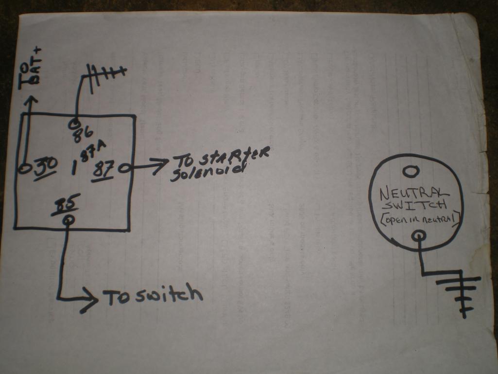
Will one of our electrical wizards help me out with this please. I want to employee the neutral switch on my Suby transmission. Oddly enough the switch is OPEN in neutral and CLOSED in gear. Life would be simpler if vice verse. (IMG:style_emoticons/default/dry.gif) My existing system is as shown in the first pic. BTW, the neutral switch is not going to ground at present or in this first pic.
 After scratching my watch and winding my ass for the past hour this 2nd pic is my solution. Question: Did I miss something obvious and could I achieve the same result by re-wiring the existing 5 pole relay? And will this work? TIA, kent 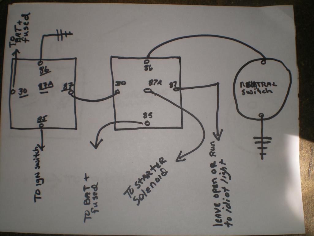 |
|
|
|
| Tom |
Nov 22 2014, 03:54 PM
Post
#37
|
|
Advanced Member Group: Members Posts: 2,139 Joined: 21-August 05 From: Port Orchard, WA 98367 Member No.: 4,626 Region Association: None |
Kent,
What are you using the neutral switch for? Starter solenoid? Safety switch so it won't start in gear ??? If that is the case, then your second schematic is correct!! You learning lectricity! (IMG:style_emoticons/default/biggrin.gif) Tom |
|
|
|
| 76-914 |
Nov 22 2014, 07:39 PM
Post
#38
|
|
Repeat Offender & Resident Subaru Antagonist Group: Members Posts: 13,663 Joined: 23-January 09 From: Temecula, CA Member No.: 9,964 Region Association: Southern California |
QUOTE(Tom @ Nov 22 2014, 01:54 PM) Kent, What are you using the neutral switch for? Starter solenoid? Safety switch so it won't start in gear ??? If that is the case, then your second schematic is correct!! You learning lectricity! (IMG:style_emoticons/default/biggrin.gif) Tom Exactly Tom. I almost took out my bench one day. (IMG:style_emoticons/default/dry.gif) Thanks for the confirmation. I'm not so sure about that learning part though. To tell the truth I learned a lot from that "2 speed 3 relay" fan set up that Bob posted. After that I began to see how you could use those switches in different ways. Now, how quickly I figure out the correct path; that is another matter. (IMG:style_emoticons/default/slits.gif) |
|
|
|
| Spoke |
Nov 23 2014, 10:57 AM
Post
#39
|
|
Jerry Group: Members Posts: 7,126 Joined: 29-October 04 From: Allentown, PA Member No.: 3,031 Region Association: None |
Nice circuit.
I redrew it to better follow the flow. Attached image(s) 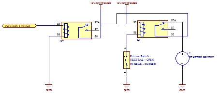
|
|
|
|
| 76-914 |
Nov 23 2014, 08:44 PM
Post
#40
|
|
Repeat Offender & Resident Subaru Antagonist Group: Members Posts: 13,663 Joined: 23-January 09 From: Temecula, CA Member No.: 9,964 Region Association: Southern California |
Well guess what. The Suby Computer didn't like it one bit. It idled up n down between 500-1200rpm every 1.5-2 seconds. Disconnected that relay from the circuit and it idles normal again. I'll have to think about this one. It's very easy to reconnect that relay later if needed.
FWIW, it worked as intended as far as not starting in gear. EDIT: I just had a thought. I'm pretty sure it was in reverse when the idle began to oscillate wildly. I shut it down immediately and removed the relay before confirming that it would do the same thing in forward or neutral! What if my backup lights let some voltage back thru the backup switch, which shares the same ground post and is located within 3" of the neutral switch. |
|
|
|
|
1 User(s) are reading this topic (1 Guests and 0 Anonymous Users)
0 Members:

|
Lo-Fi Version | Time is now: 5th February 2025 - 12:58 PM |
Invision Power Board
v9.1.4 © 2025 IPS, Inc.