|
|
|
Porsche, and the Porsche crest are registered trademarks of Dr. Ing. h.c. F. Porsche AG.
This site is not affiliated with Porsche in any way. Its only purpose is to provide an online forum for car enthusiasts. All other trademarks are property of their respective owners. |
|
|

  |

| Mike Bellis |
 Nov 24 2014, 08:48 AM Nov 24 2014, 08:48 AM
Post
#41
|
|
Resident Electrician  Group: Members Posts: 8,348 Joined: 22-June 09 From: Midlothian TX Member No.: 10,496 Region Association: None |
I have found on my Audi conversion the ECU likes to see an exact impedance from a relay. As an example, the stock main relay is 30 Ohms. A Bosch relay is 15 Ohms. I have to run 2 relays in series to match the impedance (30 Ohms). If not the ECU will see a fault. If your neutral switch is connected to the ECU in any way, the same could be happening. It would be unusual for this switch to directly connect to the ECU but it may be the case.
Using an Ohm meter you should verify the switch is completely isolated from any other circuit. If it is isolated, the effect you describe should not happen. So you may have a wiring fault. |
   |

 
|
| Spoke |
Nov 24 2014, 09:55 AM
Post
#42
|
|
Jerry Group: Members Posts: 7,373 Joined: 29-October 04 From: Allentown, PA Member No.: 3,031 Region Association: None |
QUOTE(76-914 @ Nov 23 2014, 09:44 PM)  Well guess what. The Suby Computer didn't like it one bit. It idled up n down between 500-1200rpm every 1.5-2 seconds. Disconnected that relay from the circuit and it idles normal again. I'll have to think about this one. It's very easy to reconnect that relay later if needed. FWIW, it worked as intended as far as not starting in gear. EDIT: I just had a thought. I'm pretty sure it was in reverse when the idle began to oscillate wildly. I shut it down immediately and removed the relay before confirming that it would do the same thing in forward or neutral! What if my backup lights let some voltage back thru the backup switch, which shares the same ground post and is located within 3" of the neutral switch. I'm confused on why the ECU would sense what you've done with the neutral switch. Are there connections from the neutral switch to the ECU that you didn't show in your diagrams? If there are ECU connections, measure the voltage across the switch in neutral or in gear. You would be able to use a pre-biased transistor to interface the switch. |
|
|
|
| 76-914 |
Nov 24 2014, 09:02 PM
Post
#43
|
|
Repeat Offender & Resident Subaru Antagonist Group: Members Posts: 13,878 Joined: 23-January 09 From: Temecula, CA Member No.: 9,964 Region Association: Southern California |
Spoke, no direct connections between the ECU and relays. Both the relays share the same switched ign source. The starter relay is grounded on a dedicated ss ground stud at the firewall. The neutral switch is grounded at the stock tranny ground stud along with the tranny grd and back up switch grd. I remember hearing that ECU's can suffer from ground problems and thought maybe a stray current to a nearby ground might influence the ECU. I guess not, huh? I freaked as ECU's are Voodoo to me so I wanted to disconnect the relay quickly to see if it would return to normal. It did so I will go back and explore further as Mike suggested.
Mike, your probably onto something re: a wiring fault. I re-used a "4 fuse" block that has spade fittings on the bottom. (IMG:style_emoticons/default/barf.gif) I'm going to 86 it and install a 6 fuse block with the screw terminals on the side. There are 3 circuits on the existing 4 fuse block. Backup lights/bat fused to ECU/switched fused to ECU. Sounds like I'm in the right neighborhood to begin my search. I appreciate all of you guys holding my hand while I tackle this. |
|
|
|
| Tom |
Nov 25 2014, 03:22 AM
Post
#44
|
|
Advanced Member Group: Members Posts: 2,139 Joined: 21-August 05 From: Port Orchard, WA 98367 Member No.: 4,626 Region Association: None |
Kent,
If the gear selector is in neutral, with neither relay energized, what happens? You said it hunted up and down when the gear was in reverse. next step I would do is put everything back as before when it hunted and put the gear in neutral. If it hunts, pull the power ( fuse ) for the relays and see what happens then. Oh, are any ECU sensor wires running near the relay? Tom |
|
|
|
| 76-914 |
Nov 25 2014, 09:11 AM
Post
#45
|
|
Repeat Offender & Resident Subaru Antagonist Group: Members Posts: 13,878 Joined: 23-January 09 From: Temecula, CA Member No.: 9,964 Region Association: Southern California |
That is exactly what I plan to do plus check it with the tranny in reverse as well. I hadn't thought about the ECU's sensor wires. I'll double check those.
|
|
|
|
| 76-914 |
Jul 5 2015, 09:36 PM
Post
#46
|
|
Repeat Offender & Resident Subaru Antagonist Group: Members Posts: 13,878 Joined: 23-January 09 From: Temecula, CA Member No.: 9,964 Region Association: Southern California |
I wanted an "in use" indicator light in the cockpit for the radiator fans. The fans are negatively switched and their ground wires pass thru the tunnel back to the ECU. I wondered if (IMG:style_emoticons/default/confused24.gif) I could cut in a small lamp in that ground circuit so rather than ask I thought I would try to figure it out. I used a 12v halogen flood lamp for load, a 12v test light and 12v Batt. Pos+ to the flood lamp+ / flood lamp - to test light / test light to Batt -. And yes the test lamp did light but the flood lamp did nothing; nada! (IMG:style_emoticons/default/confused24.gif) Thinking it might be location along the path I flipped them. Batt+ to test light / test light to flood lamp + / flood lamp- to Batt -. Same result. So now I wonder if this it is a demand or load thing? What is happening? Why won't the flood lamp work with the small test lamp in line? Doesn't it complete the circuit?? And what is the best way to wire in an "in use" indicator lamp? TIA, Kent
|
|
|
|
| Tom |
Jul 6 2015, 03:01 AM
Post
#47
|
|
Advanced Member Group: Members Posts: 2,139 Joined: 21-August 05 From: Port Orchard, WA 98367 Member No.: 4,626 Region Association: None |
Kent,
If you have a meter, check the resistance of the test lamp. I'm thinking it may have a high resistance, therefore limiting current for the halogen lamp when you run them in series. Any idea what the current is for the halogen. The least load for your "on" indicator light would be an LED. Very low current, so you can use small gage wires to wire it in. As a test, put an LED across the radiator fans right up by the radiator fans, in parallel - not series. See if it works ok, then pull the wires in to the cockpit to where you want the indicator lamp. If you prefer the halogen lamp and the current is high, you can use a relay in place of the LED in the above idea, then run power for the relay from a nearby source in the cockpit. As above, test the way the relay works up by the fans first. Tom |
|
|
|
| Spoke |
Jul 6 2015, 05:59 AM
Post
#48
|
|
Jerry Group: Members Posts: 7,373 Joined: 29-October 04 From: Allentown, PA Member No.: 3,031 Region Association: None |
QUOTE(Tom @ Jul 6 2015, 05:01 AM) Kent, If you have a meter, check the resistance of the test lamp. I'm thinking it may have a high resistance, therefore limiting current for the halogen lamp when you run them in series. Any idea what the current is for the halogen. The least load for your "on" indicator light would be an LED. Very low current, so you can use small gage wires to wire it in. As a test, put an LED across the radiator fans right up by the radiator fans, in parallel - not series. See if it works ok, then pull the wires in to the cockpit to where you want the indicator lamp. If you prefer the halogen lamp and the current is high, you can use a relay in place of the LED in the above idea, then run power for the relay from a nearby source in the cockpit. As above, test the way the relay works up by the fans first. Tom (IMG:style_emoticons/default/agree.gif) As mentioned, the LED indicator (actually LED + series resistor) goes in parallel with the radiators fans. Use the series resistor to limit current in the LED. Allow 5ma, 10ma of LED current. Supply voltage is 14V; LED ON voltage is about 2V. So a resistor of (14V - 2V)/5ma = 2.4k ohms or (14V - 2V)/10ma = 1.2k ohms. Choose a current where the indicator is bright enough to be seen but not too bright. Power in the resistors is I*I*R = 5ma x 5ma x 2400 = 0.06W; 10ma x 10ma x 1200 = 0.12W. So choose a resistor with at least 1/4W rating. |
|
|
|
| 76-914 |
Jul 6 2015, 08:53 AM
Post
#49
|
|
Repeat Offender & Resident Subaru Antagonist Group: Members Posts: 13,878 Joined: 23-January 09 From: Temecula, CA Member No.: 9,964 Region Association: Southern California |
Over my head. (IMG:style_emoticons/default/dry.gif) What is "I" in the equation? Any chance you could throw a hand drawn schematic at me? (IMG:style_emoticons/default/smile.gif) (IMG:style_emoticons/default/pray.gif)
|
|
|
|
| Spoke |
Jul 6 2015, 10:41 AM
Post
#50
|
|
Jerry Group: Members Posts: 7,373 Joined: 29-October 04 From: Allentown, PA Member No.: 3,031 Region Association: None |
I is current in the LED and resistor. Here's a drawing of the circuit. +12V switched can just be the positive voltage at the fan or from the fuse panel.
Attached image(s) 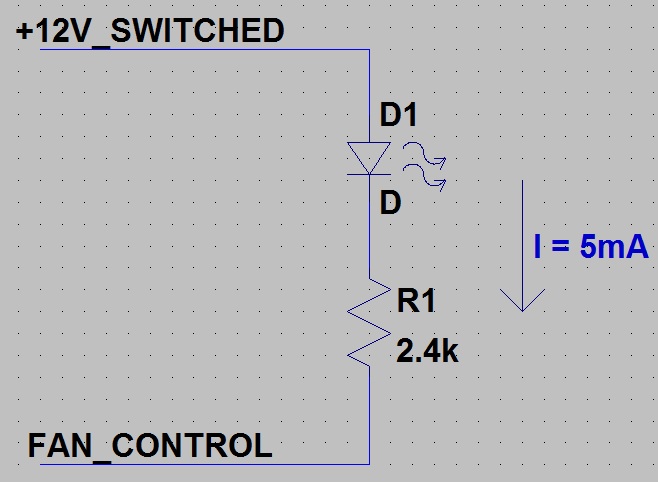
|
|
|
|
| 76-914 |
Jul 6 2015, 02:30 PM
Post
#51
|
|
Repeat Offender & Resident Subaru Antagonist Group: Members Posts: 13,878 Joined: 23-January 09 From: Temecula, CA Member No.: 9,964 Region Association: Southern California |
A million thank you's. (IMG:style_emoticons/default/pray.gif)
|
|
|
|
| 76-914 |
Oct 19 2015, 10:56 PM
Post
#52
|
|
Repeat Offender & Resident Subaru Antagonist Group: Members Posts: 13,878 Joined: 23-January 09 From: Temecula, CA Member No.: 9,964 Region Association: Southern California |
Question #10 - After someone posted a question re: the diode behind the light cluster it dawned on me that they also work on the neg path. I have 3 ground wires coming from the ECU that control the fan relays. I never knew which did what so they've all been tied together before connecting to a single relay. I want to tap into each ground so I can see when or what activates each one. What diodes do I need and hopefully a link to a place that sells them. (IMG:style_emoticons/default/pray.gif) TIA, Kent
|
|
|
|
| 76-914 |
Oct 21 2015, 08:26 AM
Post
#53
|
|
Repeat Offender & Resident Subaru Antagonist Group: Members Posts: 13,878 Joined: 23-January 09 From: Temecula, CA Member No.: 9,964 Region Association: Southern California |
(IMG:style_emoticons/default/icon_bump.gif) back to pg 1.
|
|
|
|
| 76-914 |
Jul 13 2016, 06:05 PM
Post
#54
|
|
Repeat Offender & Resident Subaru Antagonist Group: Members Posts: 13,878 Joined: 23-January 09 From: Temecula, CA Member No.: 9,964 Region Association: Southern California |
Question #11 - I want to lower my AC fan speeds about 50%. Can I use a 12v to 6v step down transformer to do this? What are your recommendations on how this can be accomplished. TIA
Question #12 - I can read (or so I say) schematics and flow charts but damned if I can draw one. (IMG:style_emoticons/default/mad.gif) I want to create a schematic that shows my new conversion wiring and where it ties into the OEM wiring. Has anyone here done that? If I saw how someone else did theirs I'm sure I could extrapolate the info I need from your schematics. Or if not, a link to on "how to" draw schematics would help. |
|
|
|
| 914forme |
Jul 13 2016, 06:19 PM
Post
#55
|
|
Times a wastin', get wrenchin'! Group: Members Posts: 3,899 Joined: 24-July 04 From: Dayton, Ohio Member No.: 2,388 Region Association: None |
Video on how to draw simple schematics
Question 11 question. Is this the internal A/C fan, or is it the electric fan on the radiator / condenser. |
|
|
|
| 76-914 |
Jul 13 2016, 06:51 PM
Post
#56
|
|
Repeat Offender & Resident Subaru Antagonist Group: Members Posts: 13,878 Joined: 23-January 09 From: Temecula, CA Member No.: 9,964 Region Association: Southern California |
QUOTE(914forme @ Jul 13 2016, 05:19 PM) Video on how to draw simple schematics Question 11 question. Is this the internal A/C fan, or is it the electric fan on the radiator / condenser. AC fan. It's a little too much unless I want to ride around with the windows rolled down. (IMG:style_emoticons/default/av-943.gif) And thx for the link. (IMG:style_emoticons/default/beerchug.gif) EDIT: OK, I watched the video and I already knew this stuff but boy did I find out something I didn't know. I had incorrectly believed that the energy of a battery flowed out the + side and returned via the - side. Shit, I had that backwards all of these years! The video says it flows out the neg side and returns on the pos side. Who knew? |
|
|
|
| stugray |
Jul 13 2016, 10:34 PM
Post
#57
|
|
Advanced Member Group: Members Posts: 3,825 Joined: 17-September 09 From: Longmont, CO Member No.: 10,819 Region Association: None |
QUOTE(76-914 @ Jul 13 2016, 06:51 PM) EDIT: OK, I watched the video and I already knew this stuff but boy did I find out something I didn't know. I had incorrectly believed that the energy of a battery flowed out the + side and returned via the - side. Shit, I had that backwards all of these years! The video says it flows out the neg side and returns on the pos side. Who knew? Current is standardized to flow out the positive terminal on a source (battery) through the load and in through the negative terminal. The electrons are now known to flow out from the negative terminal through the load and in through the positive terminal. Benjamin Franklin had a 50/50 chance when he guessed and made the standard. He just got it wrong (IMG:style_emoticons/default/headbang.gif) If you really want your mind blown consider that in semiconductors current is modeled as consisting of negative electrons flowing one way and positive "holes" flowing in the opposite direction. The direction of the flow of "holes" in a circuit matches Franklin's standard for current. As for circuit schematics, check out: http://www.123dapp.com/circuits (IMG:http://www.914world.com/bbs2/uploads_offsite/cdn.instructables.com-10819-1468470897.1.jpg) Make an account and you can build basic circuits from a box of virtual parts and a breadboard OR start in schematic editor and add components from there. You can then run a simulation of the circuit even including an arduino microcontroller complete with code. If you decide you want a circuit board made, the software can even route the lines to generate the artwork and you can order it online. It is actually amazing for free. |
|
|
|
| Spoke |
Jul 13 2016, 11:22 PM
Post
#58
|
|
Jerry Group: Members Posts: 7,373 Joined: 29-October 04 From: Allentown, PA Member No.: 3,031 Region Association: None |
QUOTE(76-914 @ Jul 13 2016, 08:05 PM) Question #11 - I want to lower my AC fan speeds about 50%. Can I use a 12v to 6v step down transformer to do this? What are your recommendations on how this can be accomplished. TIA The simplest way to slow the fan for AC is to add a power resistor in series with the fan. My '97 Audi A6 used a power resistor to provide a slower fan speed for the first level of radiator cooling. To properly size the resistor, one has to know the current draw of the fan at the reduced voltage. Did the fan come with any specifications like current draw or power rating in watts? For a starting point, let's say the current draw at 6V across the fan is 2A. (a guess) Thus the resistor has to drop 14V - 6V = 8V with 2A flowing. The resistor value needed would be 8V/2A = 4 ohm. The power dissipation of the resistor would be V x I = 8V x 2A = 16W. In this example, it would be safe to use a 50W resistor like the one below available at Digikey for less than $4. Shipping will cost more than the part. The part below is 4.7 ohm and is just an example. Adjust the numbers above as needed for actual specs or measurements. 4.7 OHM 5% 50W 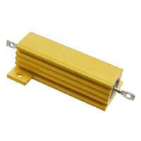 |
|
|
|
| stugray |
Jul 14 2016, 07:08 AM
Post
#59
|
|
Advanced Member Group: Members Posts: 3,825 Joined: 17-September 09 From: Longmont, CO Member No.: 10,819 Region Association: None |
The resistor would work, but for about the same amount of $$ you could use a fan speed controller for a computer:
http://www.coolerguys.com/840556089537.htm...PwizhoCiIjw_wcB (IMG:http://www.914world.com/bbs2/uploads_offsite/ep.yimg.com-10819-1468501721.1.gif) $6 ,but you would just have to find one that can handle the current. |
|
|
|
| 76-914 |
Jul 14 2016, 07:31 AM
Post
#60
|
|
Repeat Offender & Resident Subaru Antagonist Group: Members Posts: 13,878 Joined: 23-January 09 From: Temecula, CA Member No.: 9,964 Region Association: Southern California |
Stu and Jerry; thx a million. I can't wait to play with that link tonite Stu. And Jerry, I need to find that info, digest what you've provided and probably come up with 5 more questions. To quote Arnold S., "I'll be back". (IMG:style_emoticons/default/beerchug.gif)
|
|
|
|
|
1 User(s) are reading this topic (1 Guests and 0 Anonymous Users)
0 Members:

|
Lo-Fi Version | Time is now: 8th April 2026 - 11:16 AM |
Invision Power Board
v9.1.4 © 2026 IPS, Inc.