|
|
|
Porsche, and the Porsche crest are registered trademarks of Dr. Ing. h.c. F. Porsche AG.
This site is not affiliated with Porsche in any way. Its only purpose is to provide an online forum for car enthusiasts. All other trademarks are property of their respective owners. |
|
|

  |

| skeates |
 Jul 29 2014, 09:57 PM Jul 29 2014, 09:57 PM
Post
#1
|
|
Member  Group: Members Posts: 219 Joined: 28-February 05 From: Sacramento, ca Member No.: 3,684 Region Association: Northern California |
Hey guys - I'm not sure if this is a subject that has been beaten to death before (I certainly wasn't able to find any threads on it), but has anyone here ever attempted to make use of the boxster or cousin 996 gauge clusters in a conversion? I was able to find a pin-out diagram for the boxster cluster which makes it look doable. Just curious if there was any fancy shmancy communications between the cluster and the ECU that would need to be worked around?
|
   |

 
|
| Dave_Darling |
Jul 29 2014, 10:14 PM
Post
#2
|
|
914 Idiot Group: Members Posts: 15,355 Joined: 9-January 03 From: Silicon Valley / Kailua-Kona Member No.: 121 Region Association: Northern California |
Depending on the year of Boxster/996, the answer about the fancy schmancy comm protocols is either "probably" or "oh heck yes!"
--DD |
|
|
|
| jd74914 |
Jul 30 2014, 06:02 AM
Post
#3
|
|
Its alive Group: Members Posts: 4,884 Joined: 16-February 04 From: CT Member No.: 1,659 Region Association: North East States |
I would be highly surprised if the newer stuff didn't communicate with the engine and possibly transmission or any body control units via CANBUS. That said, if you are a software guy, CAN converters do exist and it's my understanding that reverse engineering CAN protocols isn't too bad.
Does your pinout have a CAN+ and CAN- wire? |
|
|
|
| stugray |
Jul 30 2014, 07:16 AM
Post
#4
|
|
Advanced Member Group: Members Posts: 3,825 Joined: 17-September 09 From: Longmont, CO Member No.: 10,819 Region Association: None |
If you have the pinouts, please post them.
I have some knowledge about CAN bus and modifying interfaces. Is this for a conversion of some type, or just a stock 914. |
|
|
|
| Mike Bellis |
Jul 30 2014, 07:45 AM
Post
#5
|
|
Resident Electrician Group: Members Posts: 8,348 Joined: 22-June 09 From: Midlothian TX Member No.: 10,496 Region Association: None |
I'm running a 2000 VW cluster and it does communicate with the ECU via can bus.
I guess the Boxster can be hacked. Chip Foose did it on a Lotus build. Please post the pin out for reference. |
|
|
|
| skeates |
Jul 30 2014, 02:45 PM
Post
#6
|
|
Member Group: Members Posts: 219 Joined: 28-February 05 From: Sacramento, ca Member No.: 3,684 Region Association: Northern California |
@ Dave_Darling: I figured anything 2004 or newer would be strait-up CANBUS, but I'm holding out hope for the first gen clusters.
So, below I've attached the pin-out diagram for a first gen boxter ('97 986). I also managed to locate some pdfs of what I assume is the factory service manual with additional info on diagnosis/troubleshooting of the instrument cluster. I know going into this that the speed and odometer functions and their derivatives all use an input signal from the ABS system that would need to be replicated. Pretty sure that's just gonna be some sort of PWM. Aside from that many of the remaining pins seem to be binary (hi/low) inputs? Right now I'm thinking these pins are the possible "problem" pins with signals to be dealt with: - ASR/ABO info (Plug I, pin 3) - ASR/ABO-SILA (Plug I, pin 4) - Speedometer A (Plug I, pin 13) ??? <- this may just be for the speed warning indicator? - K diagnosis (Plug I, pin 21) <- could be for output? - KVA DME (Plug II, pin 13) - TN Signal speed (Plug II, pin 15) - Information system in (Plug III, pin 6) - Idle period (Plug III, pin 26) I suppose I'd also need to figure out which pins need a signal for the cluster to operate at all vs. which ones can be left blank (albiet at a loss of some functionality). Anyone versed in Boxster electrical wiring? 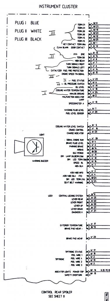 |
|
|
|
| skeates |
Jul 30 2014, 02:48 PM
Post
#7
|
|
Member Group: Members Posts: 219 Joined: 28-February 05 From: Sacramento, ca Member No.: 3,684 Region Association: Northern California |
QUOTE(stugray @ Jul 30 2014, 06:16 AM)  If you have the pinouts, please post them. I have some knowledge about CAN bus and modifying interfaces. Is this for a conversion of some type, or just a stock 914. This will be for my suby conversion. I'll be running a stand-alone ECU from AEM Electronics (http://www.aemelectronics.com/?q=products/programmable-engine-management-systems/infinity-ecu/infinity-6-8h). The engine is a normally aspirated EZ36 H-6. |
|
|
|
| jd74914 |
Jul 31 2014, 07:41 AM
Post
#8
|
|
Its alive Group: Members Posts: 4,884 Joined: 16-February 04 From: CT Member No.: 1,659 Region Association: North East States |
You are running an Infinity? Which one?
We looked at those for use on a racecar because of their extreme power, but were somewhat turned off by the lack of sophistication of traction control and lack of gearbox control (sequential tranny). I'm very interested to see how your install works out!! |
|
|
|
| CptTripps |
Jul 31 2014, 09:14 AM
Post
#9
|
|
:: Punch and Pie :: Group: Members Posts: 3,586 Joined: 26-December 04 From: Tuscaloosa, AL and Akron, OH Member No.: 3,342 Region Association: Upper MidWest |
Looking forward to seeing progress. Those clusters aren't much $, so if this could get worked out, it would be huge for Subie conversions and 6 conversions alike.
|
|
|
|
| skeates |
Jul 31 2014, 10:19 AM
Post
#10
|
|
Member Group: Members Posts: 219 Joined: 28-February 05 From: Sacramento, ca Member No.: 3,684 Region Association: Northern California |
QUOTE(jd74914 @ Jul 31 2014, 06:41 AM) You are running an Infinity? Which one? We looked at those for use on a racecar because of their extreme power, but were somewhat turned off by the lack of sophistication of traction control and lack of gearbox control (sequential tranny). I'm very interested to see how your install works out!! I'm planning on using the Infinity-6 that came out earlier this year. Since I'm not building a track-car the traction control bits didn't play into my decision making. When you look at it, these are pretty awesome engine management systems for the price tag! |
|
|
|
| jd74914 |
Jul 31 2014, 11:23 AM
Post
#11
|
|
Its alive Group: Members Posts: 4,884 Joined: 16-February 04 From: CT Member No.: 1,659 Region Association: North East States |
QUOTE(skeates @ Jul 31 2014, 11:19 AM) QUOTE(jd74914 @ Jul 31 2014, 06:41 AM) You are running an Infinity? Which one? We looked at those for use on a racecar because of their extreme power, but were somewhat turned off by the lack of sophistication of traction control and lack of gearbox control (sequential tranny). I'm very interested to see how your install works out!! I'm planning on using the Infinity-6 that came out earlier this year. Since I'm not building a track-car the traction control bits didn't play into my decision making. When you look at it, these are pretty awesome engine management systems for the price tag! Nice! Yeah, my decision was admittedly very biased by the track bits. They do look very, very nice, and are certainly attractively priced! |
|
|
|
| skeates |
Sep 3 2014, 05:44 PM
Post
#12
|
|
Member Group: Members Posts: 219 Joined: 28-February 05 From: Sacramento, ca Member No.: 3,684 Region Association: Northern California |
Ok, I bit the bullet and purchased a boxster gauge cluster off of evil-bay and for the last week or so I've been fiddling with it. The cluster (and surround) came out of a '97 Boxster, though anything up to the first part of '99 should be the same (has blue, white, and black plugs on the back).
First impressions is that the electrical aspect "should" be a cinch. After a few hours of fiddling with the cluster and a bread-board I was able to get it to turn on and start sorting out the signals. Even sort-of got the tach and speedo going. I say "sort-of" because all I have right now to generate a signal is an arduino board which can only produce a 5 V pulse-width signal. From what I can gather the cluster is expecting a 10 V signal, so the speedo only ever registered 48 MPH and the tach was a bit erratic. Next step is to swing by an electronics store to pick up an op-amp and some potentiometers so that I can simulate the different senders and test the fuel and coolant temp gauges. Also, this thing has an integrated outside air temp gauge that I'd like to get working (I'll provide some pics and video once things are set-up). In the mean time I've been tackling fitment. Looking at the cluster, I'm not sure that it would fit without a custom dash-top. Since I was planning to get a bit crazy with my interior anyways I went ahead and made sure that my cluster came with the original surround and I'm experimenting with how to incorporate it into the dash. Here is some of my preliminary progress: 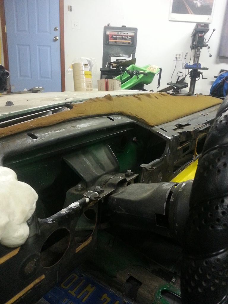 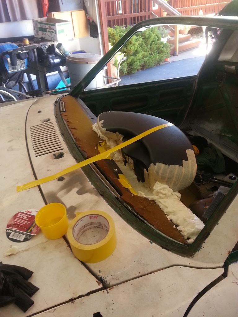 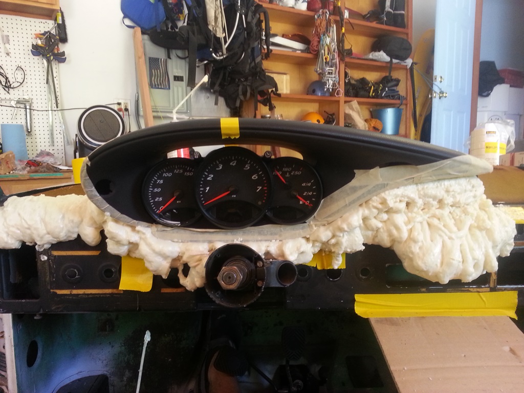 |
|
|
|
| skeates |
Sep 3 2014, 05:52 PM
Post
#13
|
|
Member Group: Members Posts: 219 Joined: 28-February 05 From: Sacramento, ca Member No.: 3,684 Region Association: Northern California |
The local hardware store was having a sale on the spray-foam insulation stuff, so I bought a bunch of it to use for shaping my new dash. This is my first time doing this, so I'm hoping things turn out, but so far it's been pretty easy to work with - just got to remember that it's sticky as hell (hench why I lined every nook and cranny of the cluster with masking tape before setting in the goo). The plan is to make a center console a-la Carrera GT style. So I fashioned a fancy pancy cardboard version to taste and then filled it with the spray foam as well for final shaping. Still a lot more shaping and whatnot to do before anything is ready for fiberglass, but the big picture is starting to become clearer now.
Will post more as I make progress (provided folks are interested). 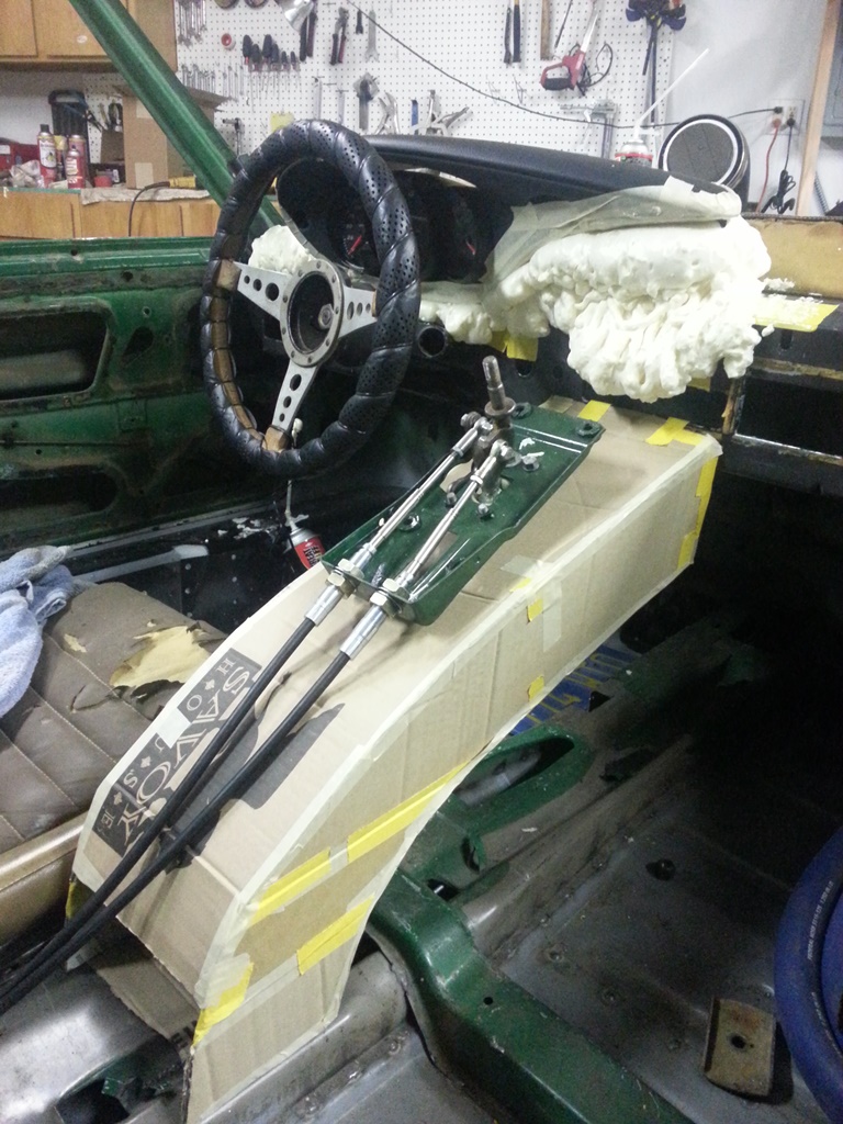 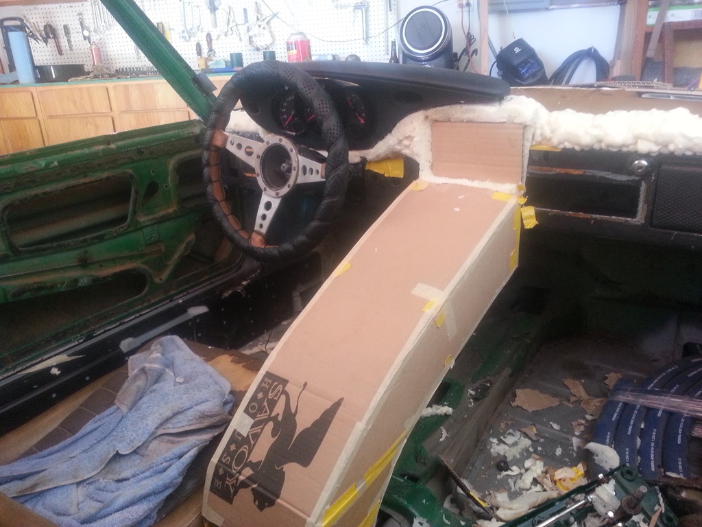 |
|
|
|
| Dave_Darling |
Sep 3 2014, 06:14 PM
Post
#14
|
|
914 Idiot Group: Members Posts: 15,355 Joined: 9-January 03 From: Silicon Valley / Kailua-Kona Member No.: 121 Region Association: Northern California |
One thing I have heard that is important here, if it's true: The expanding foam will continue to expand, slowly, for weeks.
--DD |
|
|
|
| skeates |
Sep 3 2014, 06:26 PM
Post
#15
|
|
Member Group: Members Posts: 219 Joined: 28-February 05 From: Sacramento, ca Member No.: 3,684 Region Association: Northern California |
QUOTE(Dave_Darling @ Sep 3 2014, 05:14 PM) One thing I have heard that is important here, if it's true: The expanding foam will continue to expand, slowly, for weeks. --DD Thanks for the heads-up Dave - I'll have to keep an eye on things. The can indicates that it takes 8 hours to cure so I've been spraying and then letting it sit over night before doing any shaping. I haven't noticed any movement with the stuff I've already shaped, but maybe it just hasn't been long enough yet. |
|
|
|
| skeates |
Sep 15 2014, 01:07 PM
Post
#16
|
|
Member Group: Members Posts: 219 Joined: 28-February 05 From: Sacramento, ca Member No.: 3,684 Region Association: Northern California |
So, until someone tells me this is cluttering up the web I'm going to keep posting my progress (IMG:style_emoticons/default/evilgrin.gif). Made a bit more progress on the boxster gauge cluster this weekend. First things first; even though I'm making a custom dash cap I figured I'd check to see how close this thing fits within the stock set-up. I figured if it fits that would open up a world of opportunities to those wanting to update their gauges, and stick with the Porsche feel without having to make a custom dash. So...I dug out the mounting plate for the stock gauges just to see how close the fit was (see first pic). It's hard to see in the picture, but there are two issues as I can tell which would make it difficult (though not necessarily impossible) to use this with the stock dash cap.
1) The toggles on the top of the cluster (for setting the clock, adjusting brightness, etc.) line up just about perfectly with the two top mounting screw holes. This wouldn't be too hard to work around since you'd be fabricating a custom surround to mount the gauges. At that time just move/make new tabs on the dash frame that line up. Done. 2) The second issue may be somewhat more difficult to work around. Looking at the bottom of the picture you can see that the pod housing the warning lights sticks out slightly below the bottom of the mounting plate. The boxster cluster is just a little bit too tall from what I can tell to fit within the stock dash cap - but it's such a close fit! So close that without an actual dash cap to play with I can't make any final conclusions on the possibility of making this thing fit with the stock dash cap. (if anyone wants to head up to Truckee, Ca with a stock cap to test this out with feel free to swing by (IMG:style_emoticons/default/biggrin.gif) ) 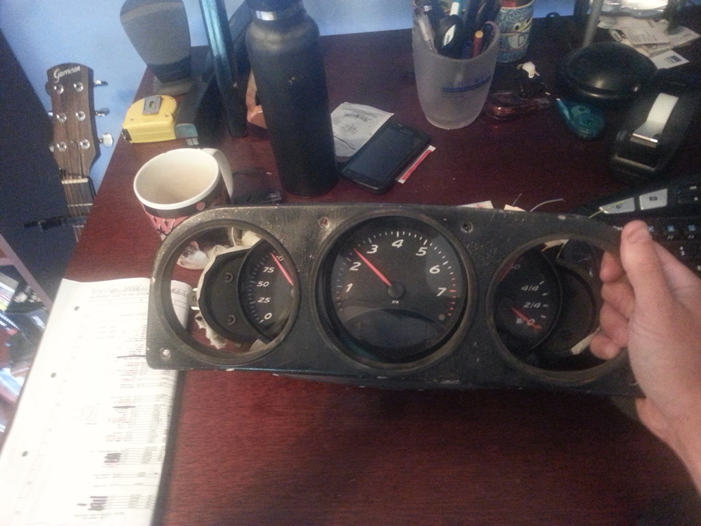 So, onto the fun stuff - electricity! I've spent more time then I care to think about tracing the boxster wiring diagrams and trying to piece together what's needed and what's not. There are several power inputs, (2) which are constant +12V and (3) more which are powered when the key is in the ACC/Drive position in the ignition. Also, there are (2) grounds for the cluster and an additional "ground" for the sender units (fuel, coolant temp, etc). In order to keep strait the mess of wires I manually pinned out and labeled each wire through the connectors. While doing so I found that many of the expected wires/inputs were "missing" from my pins. Some of these are for inputs from the tiptroic transmission which I expect to be missing on a manual cluster. Others though I think are related to the on-board computer option. At this point I'm just worried about basic functionality, so I'm not paying a whole lot of attention to the missing inputs, but they may become important later if the cluster is expecting an input that I'm not delivering. Note my pig-tails are out of a different '97 manual boxster than the gauge cluster, so there could be some miss-match happening if the options on the cars were different. Below there's a picture of my test-rig (basically just a bread board to facilitate quick & easy circuits and and arduino board that I'm using as a signal generator to simulate speedo and tach signals. 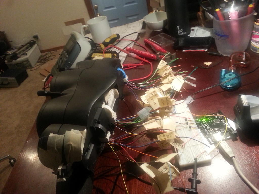 With the gauge cluster powered I then went through at tested the voltage at each (well most anyways) wire to see if any were powered. After doing this I found out something very interesting - most of the indicator lights, the speedo signal, and the tach signal are all powered and expect a ground as their "input". In the case of the speedo and tach they need to be pulled down to ground at a certain frequency, like a flickering light switch, which corresponds to the speed of the car/engine. I'm not sure whether or not this is "normal" for these types of signals, but I was expecting to have to produce a +12V signal to each, not a ground. It actually made it easier in a sense since all I needed to do was use a general purpose transistor as a switch and feed it a PWM signal from the arduino. I addition to those signals, I also got some potentiometers out to simulate the coolant temp and fuel senders. The pic below shows everything running...sort of... 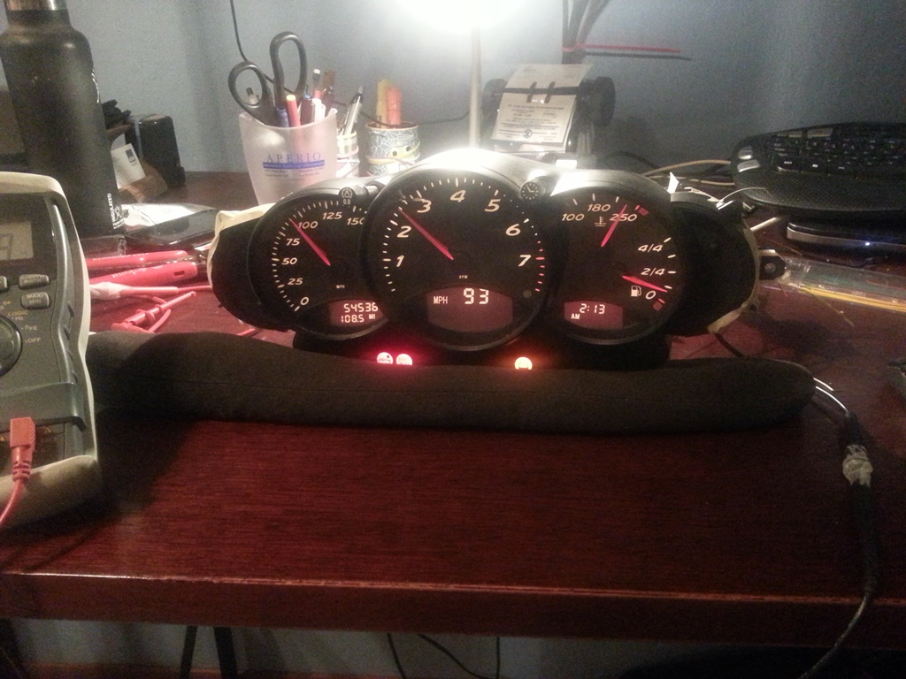 So, the moral of this story is that I've been able to get all the basic functionality working! I've got an Excel spreadsheet I use to calculate at what frequency the PWM signal needs to operate to simulate a specific MPH or RPM. I've also got the coolant temp gauge sender resistance values figured out, the gauge back-lighting/dimming is working, indicator lights are all functional, as well as the turn-signals/high beam indicators, etc.. But....and so far it's been a big pain in the butt....the damn fuel gauge is only sort-of working and represents the final piece to this puzzle. The top 3/4 of the fuel gauge range works flawlessly with a 0 - 400 Ohm potentiomter. However, as soon as you get to ~ 400 Ohms (just less than 1/4 tank) the fuel gauge drops to empty and the low fuel indicator light starts flashing. Doing some reading I found that on the 996 C4's the gas tanks were designed such that a sender wouldn't fit all the way down and then the gauge had to switch over to some sort of internal calculation approach using fuel consumption data from the ECU to estimate fuel tank levels below 12 litres. I didn't get the sense though that this was true of the C2's or the Boxters. Something definitely happens at the 1/4 tank mark where the gauge stops listening to the sender signal. In fact, once it hits that mark I can no longer get the needle to move at all by changing the resistance values. I have to do a full reset on the cluster (un-plug and plug back in) to get it to listen again. I figure it has to be looking for a signal that I'm not giving it right now, and I think I've isolated it to one or two wires: 1) There is a fuel tank status wire going to the DME (ECU) which I thought was an output, but now I'm wondering if it's an input. It has no voltage when the cluster is powered. 2) There is a wire labeled "KVA DME" on the cluster diagrams, but on the DME wiring diagram it's labeled "fuel consumption indicator". I think this one may be the missing piece, but I have no idea what signal it's sending. On the cluster this wire measures +10 V (same as the speedo and tach wires) which makes me think its looking for a similar signal to ground. My current guess it that it will somehow correspond to the fuel injector pulse signal. If anyone has any ideas (or information) on how to get the last quarter of the fuel gauge working I'd LOVE the input. It's the last 10% that takes 90% of the time/effort! |
|
|
|
| SirAndy |
Sep 15 2014, 01:22 PM
Post
#17
|
|
Resident German Group: Admin Posts: 42,488 Joined: 21-January 03 From: Oakland, Kalifornia Member No.: 179 Region Association: Northern California |
(IMG:style_emoticons/default/smilie_pokal.gif) That looks better than i thought it would!
Groupbuy? (IMG:style_emoticons/default/biggrin.gif) QUOTE(skeates @ Sep 15 2014, 12:07 PM) |
|
|
|
| Dr Evil |
Sep 17 2014, 07:36 AM
Post
#18
|
|
Send me your transmission! Group: Members Posts: 23,044 Joined: 21-November 03 From: Loveland, OH 45140 Member No.: 1,372 Region Association: MidAtlantic Region |
Wow, very nice work (IMG:style_emoticons/default/smile.gif)
|
|
|
|
| Sleepin |
Sep 17 2014, 08:49 AM
Post
#19
|
|
Advanced Member Group: Members Posts: 3,647 Joined: 20-November 07 From: Grand Junction, Co. Member No.: 8,357 Region Association: Rocky Mountains |
|
|
|
|
| boxsterfan |
Sep 17 2014, 09:05 AM
Post
#20
|
|
914's are kewl Group: Members Posts: 1,776 Joined: 6-June 03 From: San Ramon, CA Member No.: 791 Region Association: Northern California |
Fuchin' awesome!!
|
|
|
|
|
1 User(s) are reading this topic (1 Guests and 0 Anonymous Users)
0 Members:

|
Lo-Fi Version | Time is now: 20th July 2026 - 05:39 AM |
Invision Power Board
v9.1.4 © 2026 IPS, Inc.