|
|
|
Porsche, and the Porsche crest are registered trademarks of Dr. Ing. h.c. F. Porsche AG.
This site is not affiliated with Porsche in any way. Its only purpose is to provide an online forum for car enthusiasts. All other trademarks are property of their respective owners. |
|
|

  |

| Dr Evil |
 Sep 17 2014, 09:22 AM Sep 17 2014, 09:22 AM
Post
#21
|
|
Send me your transmission!  Group: Members Posts: 23,044 Joined: 21-November 03 From: Loveland, OH 45140 Member No.: 1,372 Region Association: MidAtlantic Region |
Question, just say you have to rely on the engines EFI and other things talking to each other to get the final 1/4 tank, and those parts are not used on the conversion, would it be feasible to put gauge guts from a different gauge into the pod? As in, use the needle and face of the Boxter pod, but drive the needle with a gauge with a known range and value set.
|
   |

 
|
| skeates |
Sep 17 2014, 06:34 PM
Post
#22
|
|
Member Group: Members Posts: 219 Joined: 28-February 05 From: Sacramento, ca Member No.: 3,684 Region Association: Northern California |
QUOTE(Dr Evil @ Sep 17 2014, 08:22 AM)  Question, just say you have to rely on the engines EFI and other things talking to each other to get the final 1/4 tank, and those parts are not used on the conversion, would it be feasible to put gauge guts from a different gauge into the pod? As in, use the needle and face of the Boxter pod, but drive the needle with a gauge with a known range and value set. That's an interesting idea. Not sure what things look like inside the cluster, but so long as it isn't one big circuit board that would be a good way around the problem. This weekend I should have some more time to work on this and take a gander inside. I was also wondering if there was a way to separate the pod housing the indicator lights from the rest of the cluster since that would allow this thing to be used with the stock dash. |
|
|
|
| timothy_nd28 |
Sep 17 2014, 09:35 PM
Post
#23
|
|
Advanced Member Group: Members Posts: 2,299 Joined: 25-September 07 From: IN Member No.: 8,154 Region Association: Upper MidWest |
It would be difficult to defeat the ECU communication for the 1/4-0 tank status. The gas gauge should be a standard air core motor. By opening up the gauge cluster, it would easy to sever the tracks on the circuit board to the air core motor, then wire up the aircore wire directly, like a 1967 Camaro. What do you think?
|
|
|
|
| CptTripps |
Sep 18 2014, 08:45 AM
Post
#24
|
|
:: Punch and Pie :: Group: Members Posts: 3,586 Joined: 26-December 04 From: Tuscaloosa, AL and Akron, OH Member No.: 3,342 Region Association: Upper MidWest |
(IMG:style_emoticons/default/agree.gif) with Andy. This looks a TON better than I was expecting.
You gave me a few ideas about mocking up my center console too. |
|
|
|
| skeates |
Sep 19 2014, 03:43 PM
Post
#25
|
|
Member Group: Members Posts: 219 Joined: 28-February 05 From: Sacramento, ca Member No.: 3,684 Region Association: Northern California |
QUOTE(timothy_nd28 @ Sep 17 2014, 08:35 PM) It would be difficult to defeat the ECU communication for the 1/4-0 tank status. The gas gauge should be a standard air core motor. By opening up the gauge cluster, it would easy to sever the tracks on the circuit board to the air core motor, then wire up the aircore wire directly, like a 1967 Camaro. What do you think? I had some time this afternoon to tear into the gauge cluster and look at it's internals. The first pic shows each piece of the assembly: 1) The lens covers, 2) The air-core motors and gauge lights, and 3) the circuit board driving it all. (Sorry for the blurry pic) 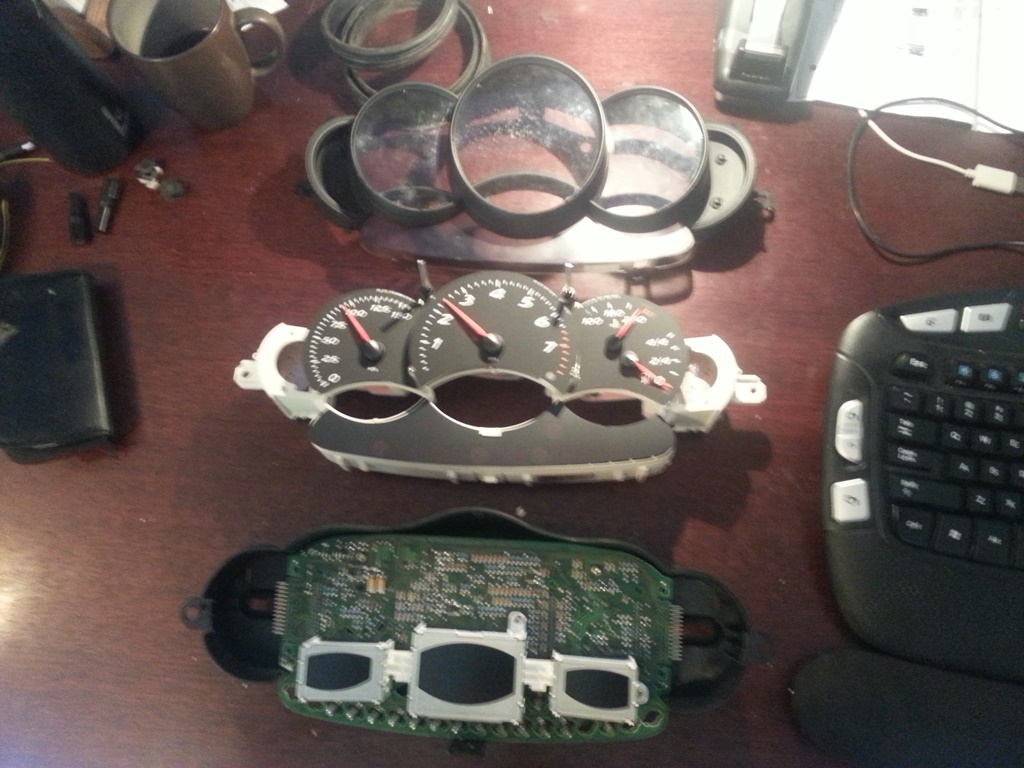 Looking at the connections, it's next to impossible (for me anyways) to try and trace the circuits driving the fuel gauge air-core motor, however; they've made it pretty easy to tap into the circuit through some header pins on the edge of the circuit board. Pics 2 and three show this connection, and I've already traced out which pins go to the two coils on the fuel gauge motor. My next question is: what's the best way to generate this signal? From what I understand it takes two PWM signals shifted by 90 degrees? This is my first time playing with air-core motors. 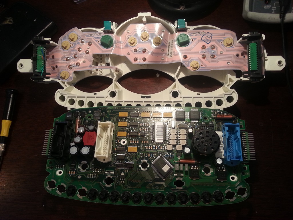 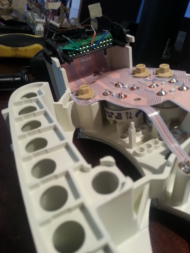 |
|
|
|
| Dr Evil |
Sep 19 2014, 03:47 PM
Post
#26
|
|
Send me your transmission! Group: Members Posts: 23,044 Joined: 21-November 03 From: Loveland, OH 45140 Member No.: 1,372 Region Association: MidAtlantic Region |
Oooooo (IMG:style_emoticons/default/smile.gif)
I like the splicing into the OE motor method mentioned. (IMG:style_emoticons/default/smile.gif) I hope it works. |
|
|
|
| timothy_nd28 |
Sep 19 2014, 04:07 PM
Post
#27
|
|
Advanced Member Group: Members Posts: 2,299 Joined: 25-September 07 From: IN Member No.: 8,154 Region Association: Upper MidWest |
To see how this air core motor is wired internally, we need resistances from each leg to each other leg, a total of 12 numbers, tabulated and identified to which connections are being measured (should be 4 terminals).
|
|
|
|
| skeates |
Sep 19 2014, 04:45 PM
Post
#28
|
|
Member Group: Members Posts: 219 Joined: 28-February 05 From: Sacramento, ca Member No.: 3,684 Region Association: Northern California |
QUOTE(timothy_nd28 @ Sep 19 2014, 03:07 PM) To see how this air core motor is wired internally, we need resistances from each leg to each other leg, a total of 12 numbers, tabulated and identified to which connections are being measured (should be 4 terminals). Here are the measurements you spoke of (See pic below for pin ID). Looks to me like the coils are: Coil 1: Pin1 to Pin3 Coil 2: Pin2 to Pin4 Is there any way to figure out which is the Sin coil and which is the Cos? 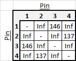 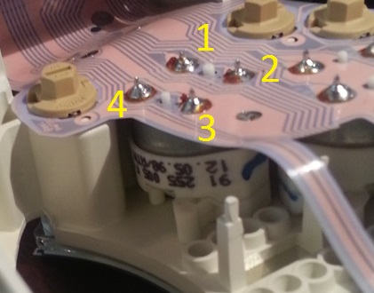 |
|
|
|
| worn |
Sep 19 2014, 07:13 PM
Post
#29
|
|
Winner of the Utah Twisted Joint Award Group: Members Posts: 3,624 Joined: 3-June 11 From: Madison, WI and North Bend WA Member No.: 13,152 Region Association: Upper MidWest |
QUOTE(skeates @ Sep 19 2014, 01:43 PM) It would be difficult to defeat the ECU communication for the 1/4-0 tank status. The gas gauge should be a standard air core motor. By opening up the gauge cluster, it would easy to sever the tracks on the circuit board to the air core motor, then wire up the aircore wire directly, like a 1967 Camaro. What do you think? Looking at the connections, it's next to impossible (for me anyways) to try and trace the circuits driving the fuel gauge air-core motor, however; they've made it pretty easy to tap into the circuit through some header pins on the edge of the circuit board. Pics 2 and three show this connection, and I've already traced out which pins go to the two coils on the fuel gauge motor. My next question is: what's the best way to generate this signal? From what I understand it takes two PWM signals shifted by 90 degrees? This is my first time p I don't think we are in Kansas anymore. Ohm isn't gonna help me with this one, is he? (IMG:style_emoticons/default/popcorn[1].gif) |
|
|
|
| timothy_nd28 |
Sep 19 2014, 07:53 PM
Post
#30
|
|
Advanced Member Group: Members Posts: 2,299 Joined: 25-September 07 From: IN Member No.: 8,154 Region Association: Upper MidWest |
Ok. If you reset the board and have the fuel gauge reading full, measure the voltage across 1 (red lead) and 3 (black lead) and then across 2 (red lead) and 4 (black Lead). Then set the fuel level to half full and repeat the measurements. This will tell us max voltage on the coils, which one is sine and which is cosine, and the polarity of the terminals. We then will have all the information required to make the modification.
|
|
|
|
| 904svo |
Sep 19 2014, 08:14 PM
Post
#31
|
|
904SVO Group: Members Posts: 1,129 Joined: 17-November 05 From: Woodstock,Georgia Member No.: 5,146 |
From the reading you have a stepper motor gas gauge, you could try to set your
pot to give a full reading on one set of the windings and another pot with reversed battery and ground to give a empty reading ( gas gauge sender ). |
|
|
|
| skeates |
Sep 19 2014, 11:28 PM
Post
#32
|
|
Member Group: Members Posts: 219 Joined: 28-February 05 From: Sacramento, ca Member No.: 3,684 Region Association: Northern California |
Just finished taking some voltage readings on the terminals. Looks like they each oscillate between negative 5 volts and positive 5 volts, but at a very slow rate (probably takes about a full minute to go through a cycle. Seems like I might need an oscilloscope to figure out what this signal is looking like.
|
|
|
|
| timothy_nd28 |
Sep 19 2014, 11:35 PM
Post
#33
|
|
Advanced Member Group: Members Posts: 2,299 Joined: 25-September 07 From: IN Member No.: 8,154 Region Association: Upper MidWest |
Is the needle fixed at full level but the voltages are still changing from -5 to +5 volts?
The voltages should be stable when the needle stops moving. |
|
|
|
| skeates |
Sep 20 2014, 12:03 AM
Post
#34
|
|
Member Group: Members Posts: 219 Joined: 28-February 05 From: Sacramento, ca Member No.: 3,684 Region Association: Northern California |
QUOTE(timothy_nd28 @ Sep 19 2014, 10:35 PM) Is the needle fixed at full level but the voltages are still changing from -5 to +5 volts? The voltages should be stable when the needle stops moving. It's hard to say whether or not the needle was indeed in it's full position since I cannot take the measurements while it is hooked up to the motor (The components get in the way of a measurement since two of the pins are buried on the bottom). I did give it a good chunk of time though to see if it would stabilize. That said - given my (limited) understanding of air-core motors, wouldn't we expect for the voltage to vary? I was under the impression that they expected inputs in the form of current oscillating in sin/cos wave fashion? Looks like I'm going to have to pick up some parts to build a motor driver tomorrow |
|
|
|
| Dr Evil |
Sep 20 2014, 08:04 AM
Post
#35
|
|
Send me your transmission! Group: Members Posts: 23,044 Joined: 21-November 03 From: Loveland, OH 45140 Member No.: 1,372 Region Association: MidAtlantic Region |
While I dig the scholastic effort in figuring out the step frequency and such, I must wonder if the modification of a stock 914 fuel gauge into the panel would not be loads simpler as you can then use the stock sender, and tank, and..... However, I in no way wish to dissuade you from the path you have chosen as it is very interesting (IMG:style_emoticons/default/smile.gif)
Is the sweep angle the same or similar between the 914 and boxter units? |
|
|
|
| timothy_nd28 |
Sep 20 2014, 08:08 AM
Post
#36
|
|
Advanced Member Group: Members Posts: 2,299 Joined: 25-September 07 From: IN Member No.: 8,154 Region Association: Upper MidWest |
No, the voltages do not oscillate as in a motor, but rather each coil generates a magnetic field, and being at 90 degrees of each other, generate a magnetic field at an angle of atan(I coil1/I coil2). So you can achieve deflection of +/-45 degrees with a current level from 0 to max in coil1 (simultaneously changing current in coil2 from max to 0). There is a bar magnet on the needle which aligns with this field, causing the needle to move.
Try to solder wires on the motor pins and re-assemble to run the test and take measurements. |
|
|
|
| Dr Evil |
Sep 20 2014, 08:15 AM
Post
#37
|
|
Send me your transmission! Group: Members Posts: 23,044 Joined: 21-November 03 From: Loveland, OH 45140 Member No.: 1,372 Region Association: MidAtlantic Region |
Fascinating. I have never heard of aircore gauges. More explanation here:
http://en.wikipedia.org/wiki/Air_core_gauge Pretty cool. I am used to the old school type of single coil. |
|
|
|
| timothy_nd28 |
Sep 20 2014, 08:57 AM
Post
#38
|
|
Advanced Member Group: Members Posts: 2,299 Joined: 25-September 07 From: IN Member No.: 8,154 Region Association: Upper MidWest |
In my signature, i did a write up on how to do a tach conversion with a air core motor.
|
|
|
|
| Dr Evil |
Sep 20 2014, 11:27 AM
Post
#39
|
|
Send me your transmission! Group: Members Posts: 23,044 Joined: 21-November 03 From: Loveland, OH 45140 Member No.: 1,372 Region Association: MidAtlantic Region |
Looked at it, bumped it (IMG:style_emoticons/default/smile.gif) Good stuff.
Would the stock gas tank sender be able to be made to work with the aircore? Would an interface be needed that would change the signal from the sensor into a signal that they aircore could use? |
|
|
|
| timothy_nd28 |
Sep 20 2014, 11:48 AM
Post
#40
|
|
Advanced Member Group: Members Posts: 2,299 Joined: 25-September 07 From: IN Member No.: 8,154 Region Association: Upper MidWest |
Absolutely using the original sender, everything will be plug and play after the modification
|
|
|
|
|
1 User(s) are reading this topic (1 Guests and 0 Anonymous Users)
0 Members:

|
Lo-Fi Version | Time is now: 13th July 2026 - 12:12 AM |
Invision Power Board
v9.1.4 © 2026 IPS, Inc.