|
|
|
Porsche, and the Porsche crest are registered trademarks of Dr. Ing. h.c. F. Porsche AG.
This site is not affiliated with Porsche in any way. Its only purpose is to provide an online forum for car enthusiasts. All other trademarks are property of their respective owners. |
|
|

  |

| malcolm2 |
 Oct 14 2014, 09:00 PM Oct 14 2014, 09:00 PM
Post
#1
|
|
Advanced Member  Group: Members Posts: 2,738 Joined: 31-May 11 From: Nashville Member No.: 13,139 Region Association: South East States |
I have had this gauge for a while. I also found the complete taco plate, sender etc... to set it up. I decided to test it. I tested the sender a while back in hot water and remember getting various readings as the temp increased.
I pulled out my 12v powered drill battery, put 12v + on the + terminal of the gauge and the - on the - of the gauge. ( you can't see the - wire in the picture, but it is there) The gauge moved to where it is in the picture without the sender even being connected. It did not move once the sender was connected. Inside the temp gauge are the following #s. Far left 30, at the start of the red line 156.7 and the end of the red line 170 *C The top of the paper is what is stamped on each face of the hex and the gauge part # has been edited to what you see in the picture. 1. why is the gauge moving at room temp with or with out the sender? 2. do I have this thing hooked up right? any alternate testing suggestions? 3. do I have a matched sender & gauge? 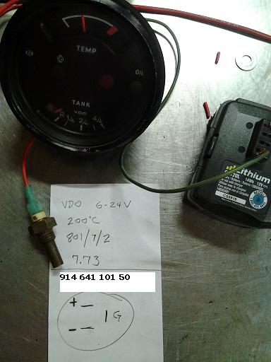 |
   |

 
|
| bdstone914 |
Oct 14 2014, 09:10 PM
Post
#2
|
|
bdstone914 Group: Members Posts: 4,512 Joined: 8-November 03 From: Riverside CA Member No.: 1,319 |
QUOTE(malcolm2 @ Oct 14 2014, 08:00 PM)  I have had this gauge for a while. I also found the complete taco plate, sender etc... to set it up. I decided to test it. I tested the sender a while back in hot water and remember getting various readings as the temp increased. I pulled out my 12v powered drill battery, put 12v + on the + terminal of the gauge and the - on the - of the gauge. ( you can't see the - wire in the picture, but it is there) The gauge moved to where it is in the picture without the sender even being connected. It did not move once the sender was connected. Inside the temp gauge are the following #s. Far left 30, at the start of the red line 156.7 and the end of the red line 170 *C The top of the paper is what is stamped on each face of the hex and the gauge part # has been edited to what you see in the picture. 1. why is the gauge moving at room temp with or with out the sender? 2. do I have this thing hooked up right? any alternate testing suggestions? 3. do I have a matched sender & gauge? You should have a ground wire from the case of the sender to the ground of the battery. If you directly ground the sender wire it should peg the gauge. I can't explain why the gauge should register at ambient temp without the sender grounded. It looks like a metal table. Is the negative terminal of the gauge touching the table? |
|
|
|
| malcolm2 |
Oct 14 2014, 09:34 PM
Post
#3
|
|
Advanced Member Group: Members Posts: 2,738 Joined: 31-May 11 From: Nashville Member No.: 13,139 Region Association: South East States |
I have tried this set up on the car's battery too. +of the gauge to + of the car's batt. ground of the gauge to - of the car's batt. and the gauge moves and stays were it is in the picture. nothing I do to the sender causes any movement or change of the needle.
|
|
|
|
| malcolm2 |
Oct 15 2014, 05:32 AM
Post
#4
|
|
Advanced Member Group: Members Posts: 2,738 Joined: 31-May 11 From: Nashville Member No.: 13,139 Region Association: South East States |
|
|
|
|
| bdstone914 |
Oct 15 2014, 06:47 AM
Post
#5
|
|
bdstone914 Group: Members Posts: 4,512 Joined: 8-November 03 From: Riverside CA Member No.: 1,319 |
Sounds like the gauge may be faulty. Did you try grounding the sender wire to see if it pegs the needle?
|
|
|
|
| malcolm2 |
Oct 15 2014, 06:53 AM
Post
#6
|
|
Advanced Member Group: Members Posts: 2,738 Joined: 31-May 11 From: Nashville Member No.: 13,139 Region Association: South East States |
QUOTE(bdstone914 @ Oct 15 2014, 07:47 AM) Sounds like the gauge may be faulty. Did you try grounding the sender wire to see if it pegs the needle? Yes, I used a medium sized aligator clip. Clipped to the threads of the sender then to a nut on the engine. All this during the car battery test. The needle only wiggled slightly as the ground connection was being made. |
|
|
|
| stugray |
Oct 15 2014, 08:11 AM
Post
#7
|
|
Advanced Member Group: Members Posts: 3,824 Joined: 17-September 09 From: Longmont, CO Member No.: 10,819 Region Association: None |
QUOTE(malcolm2 @ Oct 15 2014, 06:53 AM) QUOTE(bdstone914 @ Oct 15 2014, 07:47 AM) Sounds like the gauge may be faulty. Did you try grounding the sender wire to see if it pegs the needle? Yes, I used a medium sized aligator clip. Clipped to the threads of the sender then to a nut on the engine. All this during the car battery test. The needle only wiggled slightly as the ground connection was being made. I believe he means ground the sensor wire from the gauge. This should peg the meter at ~300 deg. |
|
|
|
| bdstone914 |
Oct 15 2014, 08:41 AM
Post
#8
|
|
bdstone914 Group: Members Posts: 4,512 Joined: 8-November 03 From: Riverside CA Member No.: 1,319 |
QUOTE(stugray @ Oct 15 2014, 07:11 AM) QUOTE(malcolm2 @ Oct 15 2014, 06:53 AM) QUOTE(bdstone914 @ Oct 15 2014, 07:47 AM) Sounds like the gauge may be faulty. Did you try grounding the sender wire to see if it pegs the needle? Yes, I used a medium sized aligator clip. Clipped to the threads of the sender then to a nut on the engine. All this during the car battery test. The needle only wiggled slightly as the ground connection was being made. I believe he means ground the sensor wire from the gauge. This should peg the meter at ~300 deg. Yes. Ground the terminal from the gauge directly. That will tell if the gauge responds correctly. |
|
|
|
| malcolm2 |
Oct 15 2014, 09:40 AM
Post
#9
|
|
Advanced Member Group: Members Posts: 2,738 Joined: 31-May 11 From: Nashville Member No.: 13,139 Region Association: South East States |
QUOTE(bdstone914 @ Oct 15 2014, 09:41 AM) Ground the terminal from the gauge directly. That will tell if the gauge responds correctly. Ah, I have not tried that. I'll try it this afternoon. The "circle" in the picture is the back of the gauge showing the individual gauge wire connections. + of the gauge to + of a batt. ground of the gauge to - of the batt "G" of the gauge to ground. If I do this on the car battery I can find a clean ground on the car and ground the "G". If I do it on the bench, should I use the - on the test battery? If the NEEDLE does not peg to max, I have a gauge issue? That's what you are saying? 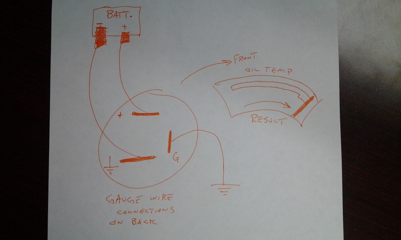 |
|
|
|
| bdstone914 |
Oct 15 2014, 09:57 AM
Post
#10
|
|
bdstone914 Group: Members Posts: 4,512 Joined: 8-November 03 From: Riverside CA Member No.: 1,319 |
With either battery just jump from the G to - on the back of the gauge with the positive and negative wires connected to the battery. I think it will peg the gauge. It sounds like you gave a weak short to ground on the G terminal. Take that part of the gauge out and inspect it. You may have something touching the case and the G terminal. The gauge is responding to a signal when there should not be a signal.
|
|
|
|
| StratPlayer |
Oct 15 2014, 11:26 AM
Post
#11
|
|
StratPlayer Group: Members Posts: 3,264 Joined: 27-December 02 From: SLC, Utah Member No.: 27 Region Association: Rocky Mountains |
So if the gauge pegs that means the gauge is good using this test?
|
|
|
|
| timothy_nd28 |
Oct 15 2014, 11:37 AM
Post
#12
|
|
Advanced Member Group: Members Posts: 2,299 Joined: 25-September 07 From: IN Member No.: 8,154 Region Association: Upper MidWest |
For this gauge to act correctly, all wires need to be connected. The actual gauge part has a spring return with two sets of windings that are 90 degrees apart from one another. If the G terminal is not connected, the gauge will float because part of the windings are not biased properly. I didn't see anything out of the ordinary from your initial post, as the gauge behaved as it should with a missing G signal.
I recently integrated a temp gauge in a standard combo gauge for Rnellums, and even with the newer style gauge motors, it did the exact same thing,,because the G wire was floating. I don't think you have anything to worry about. Bruce is correct when he explained how to bench test the gauge. By applying ground to the G terminal, the needle will deflect fully. It's a quick and easy test. If you were to tie the sensor case to the gauge ground, then tie the sensors' isolated terminal to the G terminal, then finally tie power to the gauges + and - terminals, you should see everything work as it should. Then obtain a pot of deionized water, and dip your sender inside this pot while the water is boiling. It's a bunch of mickey mousing around, but a good way to see if your gauge is calibrated and trustworthy. My wife gave me a crazy look, when I had my hands full of jumper wires attached to a car battery while on top of the kitchen stove. (IMG:style_emoticons/default/blink.gif) I told her that I was making a prototype cold fusion reactor! |
|
|
|
| malcolm2 |
Oct 15 2014, 11:47 AM
Post
#13
|
|
Advanced Member Group: Members Posts: 2,738 Joined: 31-May 11 From: Nashville Member No.: 13,139 Region Association: South East States |
QUOTE(bdstone914 @ Oct 15 2014, 10:57 AM) The gauge is responding to a signal when there should not be a signal. Thanks Bruce, That is a good way to put it, I do understand that. Last night I took the 4 screws out of that part of the gauge and removed it from the case. That is how I found the # along the top edge marking the beginning and the red section. I reinstalled it, but I will remove it once more and take a closer look at the guts of this individual gauge. And I will try your suggestion. It is alittle easier to just connect the G term. to the ground term on the back. 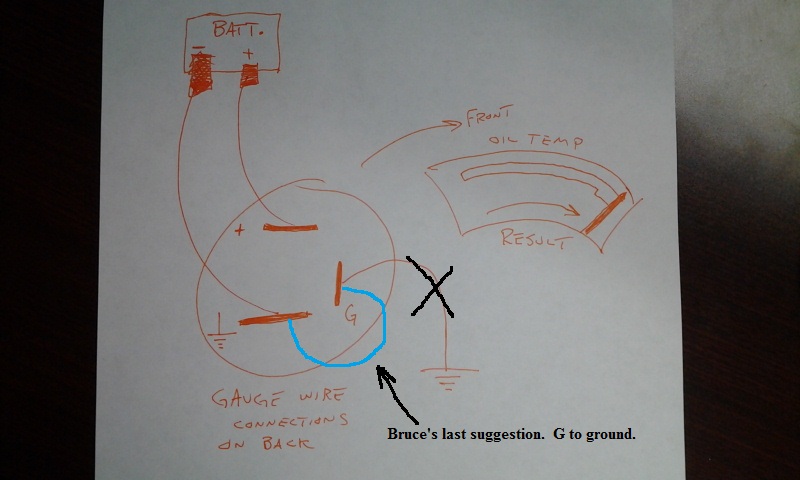 |
|
|
|
| timothy_nd28 |
Oct 15 2014, 11:54 AM
Post
#14
|
|
Advanced Member Group: Members Posts: 2,299 Joined: 25-September 07 From: IN Member No.: 8,154 Region Association: Upper MidWest |
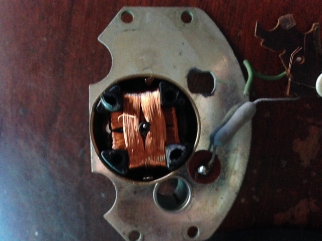
Closer look of the guts:
 |
|
|
|
| malcolm2 |
Oct 15 2014, 12:21 PM
Post
#15
|
|
Advanced Member Group: Members Posts: 2,738 Joined: 31-May 11 From: Nashville Member No.: 13,139 Region Association: South East States |
QUOTE(timothy_nd28 @ Oct 15 2014, 12:54 PM) Closer look of the guts: I just took it out, I did not crack it open. I'll go thru what you and Bruce have suggested before I do go too deep. fingers are crossed. (IMG:style_emoticons/default/stirthepot.gif) Thanks to all for the help..... so far. (IMG:style_emoticons/default/lol-2.gif) |
|
|
|
| Dave_Darling |
Oct 15 2014, 01:30 PM
Post
#16
|
|
914 Idiot Group: Members Posts: 14,981 Joined: 9-January 03 From: Silicon Valley / Kailua-Kona Member No.: 121 Region Association: Northern California |
Just to make sure:
You know that the "G" on the back of the gauge does not stand for "ground", right? It's for "sender" (in German). So that terminal gets hooked up to the terminal on the back of the sender, and the threaded part of the sender gets hooked up to a ground. Like the ground terminal on the back of the gauge. I'm just trying to make sure of the "did you turn it on" type of questions... --DD |
|
|
|
| malcolm2 |
Oct 15 2014, 05:18 PM
Post
#17
|
|
Advanced Member Group: Members Posts: 2,738 Joined: 31-May 11 From: Nashville Member No.: 13,139 Region Association: South East States |
QUOTE(Dave_Darling @ Oct 15 2014, 02:30 PM) Just to make sure: You know that the "G" on the back of the gauge does not stand for "ground", right? It's for "sender" (in German). So that terminal gets hooked up to the terminal on the back of the sender, and the threaded part of the sender gets hooked up to a ground. Like the ground terminal on the back of the gauge. I'm just trying to make sure of the "did you turn it on" type of questions... --DD Process of elimination turned out to be pretty obvious. The connectors on the back are marked with a "+" and the international sign for ground which can't be typed with a qwerty key board and the the mystery "G". So what is the German word for SENDER? The fuel gauge has all the same markings. I am home now and 'bout ready to give the suggested test method a try. Maybe one more (IMG:style_emoticons/default/beer3.gif) It is Hump day, you know. |
|
|
|
| malcolm2 |
Oct 15 2014, 06:26 PM
Post
#18
|
|
Advanced Member Group: Members Posts: 2,738 Joined: 31-May 11 From: Nashville Member No.: 13,139 Region Association: South East States |
(IMG:style_emoticons/default/beerchug.gif)
I need to thank everyone for their help and comments and support. Everything has proven successful. The needle did peg to the right when i placed a jumper from the ground terminal to the "G" terminal while supplying 12v + and - to the proper terminals. The green wire goes to the ground term. the single red goes to the + term and the red with the green is the jumper to the "G" 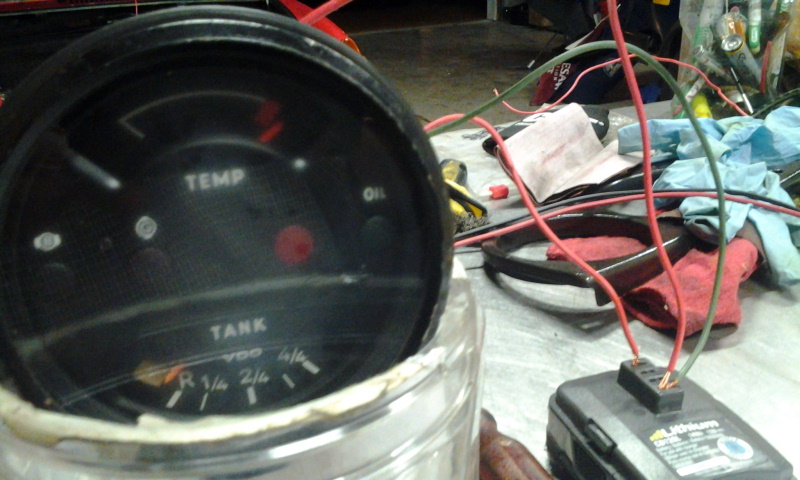 And the sender in boiling water test has given me a reference for 212* F.... Probably a little too close to the red line for my taste, but I guess I will get used to it. 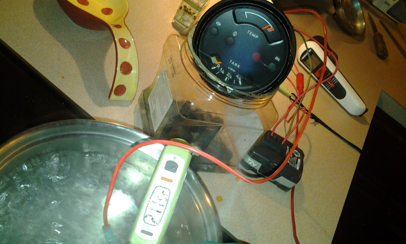 |
|
|
|
| timothy_nd28 |
Oct 15 2014, 06:43 PM
Post
#19
|
|
Advanced Member Group: Members Posts: 2,299 Joined: 25-September 07 From: IN Member No.: 8,154 Region Association: Upper MidWest |
I'm not sure where the needle should point at 212 degree's F. I think it's too close to the red mark for such a low temp. If you buy a 1k potentiometer from your local radio shack, you could wire it in series with the sender. Perform the test again, and adjust the pot till the needle is somewhere in the middle. Then if you carefully remove the pot from the circuit and measure the resistance, you could buy a fixed resistor with that value and hard wire it in the circuit.
Just a thought |
|
|
|
| Mblizzard |
Oct 15 2014, 07:44 PM
Post
#20
|
|
Advanced Member Group: Members Posts: 3,033 Joined: 28-January 13 From: Knoxville Tn Member No.: 15,438 Region Association: South East States |
Anyone figure out Clark is an engineer?
I know some of the other gauges have some reference values printed al g the very top part of the gauge. Not sure if the combo is the same. |
|
|
|
|
1 User(s) are reading this topic (1 Guests and 0 Anonymous Users)
0 Members:

|
Lo-Fi Version | Time is now: 25th April 2024 - 06:12 PM |
Invision Power Board
v9.1.4 © 2024 IPS, Inc.