|
|
|
Porsche, and the Porsche crest are registered trademarks of Dr. Ing. h.c. F. Porsche AG.
This site is not affiliated with Porsche in any way. Its only purpose is to provide an online forum for car enthusiasts. All other trademarks are property of their respective owners. |
|
|


| sdoolin |
 Jan 13 2016, 04:29 PM Jan 13 2016, 04:29 PM
Post
#141
|
|
Member  Group: Members Posts: 423 Joined: 1-May 14 From: LouKY Member No.: 17,299 Region Association: None |
Yep, I am building a 2056. Have ordered very nearly a complete 2056 engine kit from Type IV Store (LN Engineering). Some questions (I have searched and read MANY threads)...
I have a "spare" 1976 VW Bus short block (no cyl. heads). Assume this will work for a starting point? Issues with oil dipstick? The bus was an automatic so I assume once I remove the "flex plate" that the flywheel from by 914 engine (in car) will bolt up to the crank without issues? Any issues with engine carrier? The bus used a "moustache bar" for mounting to the frame and I am hoping that the cases from the bus/914 are the same for engine mounting? Will re-use existing Crank/rods New crank/rod bearings Will re-use existing cylinders (overbored) KB 96 mm flat topped pistons with Hastings rings Webcam cam (9130 kit from Type IV Store) Type IV Store pushrods, pushrod ends, parkerized lifters, rocker shafts Type IV Store cam bearings Re-use rockers from bus engine? Not sure about this... HAM (Len Hoffman) RS+ spec cylinder heads New Oil pump from Type IV Store New clutch & pressure plate. Re-use flywheel from 914 engine (in the car) Dellorto Dual 40mm carbs, CB Perf manifolds & linkage SSI heat exchangers & Bursch exhaust New fuel pump - will run return lines (have CFR SS Lines in car now and will re-use) Not sure what dizzy to run? I believe I need to check/verify deck height and valve clearance (I know how, just not positive this is required for a 2056 build). I have read a few threads about "setting" compression ration, but do not understand it yet? Anyone have a compression ratio for dummies guide? Anything else I'm missing? Progress so far... 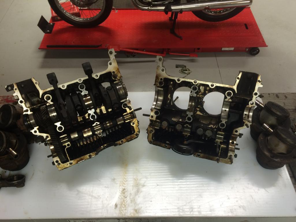 |
   |

 
|
Posts in this topic
 sdoolin Just another 2056 build Jan 13 2016, 04:29 PM
 Valy Block off the bus oil dipstick hookup and install ... Jan 13 2016, 04:52 PM Dave_Darling I have read a few threads about "setting... Jan 13 2016, 06:30 PM sdoolin Valy - thanks for the info. The case I am hoping t... Jan 14 2016, 06:05 AM The Cabinetmaker Why not source a 914 case? Jan 14 2016, 07:14 AM
 sdoolin
Why not source a 914 case?
Good question. I had... Jan 14 2016, 07:47 AM r_towle Check to make sure it's straight, the crank jo... Jan 14 2016, 07:33 PM McMark Yup, check condition of the case before you put mo... Jan 15 2016, 08:47 AM Jesco Reient
Yup, check condition of the case before you put m... Jan 16 2016, 11:32 AM malcolm2 Sorry I did not read thru the whole post and all c... Jan 15 2016, 12:31 PM sdoolin
Sorry I did not read thru the whole post and all ... Jan 15 2016, 06:26 PM The Cabinetmaker
Sorry I did not read thru the whole post and all ... Jan 16 2016, 03:35 PM Sedonut You should be able to buy a 914 case cheap. Like m... Jan 15 2016, 02:39 PM sdoolin
You should be able to buy a 914 case cheap. Like ... Jan 15 2016, 06:13 PM ericoneal I also have a 2.0 engine and am in the process of ... Jan 15 2016, 09:42 PM Dave_Darling The 914 flywheel will bolt to the Bus crank. Ther... Jan 15 2016, 09:19 PM Jake Raby Thats a solid combo. Put it at 9:1 and it'll b... Jan 15 2016, 11:05 PM Jesco Reient To be sure you want to make sure that before you d... Jan 15 2016, 11:25 PM r_towle
To be sure you want to make sure that before you ... Jan 16 2016, 03:48 PM G e o r g e
[quote name='Jesco Reient' post='2290293' date='J... Jan 16 2016, 05:12 PM Jesco Reient
[quote name='Jesco Reient' post='2290293' date='J... Jan 16 2016, 05:39 PM sdoolin OK then. Lots of good/useful info - thanks everyon... Jan 16 2016, 09:38 AM ThePaintedMan I believe the gentleman that just posted, Jesco Re... Jan 16 2016, 11:41 AM stugray
I believe the gentleman that just posted, Jesco R... Jan 16 2016, 02:22 PM sdoolin
I believe the gentleman that just posted, Jesco R... Jan 16 2016, 03:04 PM Jesco Reient
I believe the gentleman that just posted, Jesco ... Jan 16 2016, 05:33 PM sdoolin OK OK OK OK y'all are scaring me!
I don... Jan 16 2016, 03:01 PM Cairo94507 Wow. That's the way to do it. :trophy: Jan 17 2016, 08:30 AM sdoolin Today's progress. Cleaned case halves (to the ... Jan 17 2016, 06:15 PM sdoolin Unusual damage to #4 cylinder deck. I must not be ... Jan 17 2016, 06:19 PM sdoolin Case halves don't look too too bad...
Jan 17 2016, 06:23 PM sdoolin Still looking for an East coast/local shop to meas... Jan 24 2016, 08:45 AM stugray
Anyone have a link to that information?
PM sent Jan 24 2016, 11:35 AM wndsrfr
Still looking for an East coast/local shop to mea... Jan 24 2016, 07:00 PM sdoolin
Still looking for an East coast/local shop to me... Jan 25 2016, 06:56 AM sdoolin Update - cases are out being measured (crank bore ... Jan 27 2016, 09:07 AM Java2570 You might check with Brad Mayeur at 914 LTD about ... Jan 27 2016, 11:13 AM sdoolin
You might check with Brad Mayeur at 914 LTD about... Jan 27 2016, 02:36 PM sdoolin So the news is in...
My local guy says that these... Feb 3 2016, 08:57 PM Dave_Darling My local guy says that these cases do NOT need ali... Mar 4 2016, 07:06 PM sdoolin Just received a pair of HAM RS+ Spec Cyl. Heads. T... Mar 4 2016, 04:57 PM sdoolin More RS+ Porn...
Notice the machinng/work done at... Mar 4 2016, 05:04 PM sdoolin
He means my specific case. He measured the crank... Mar 4 2016, 07:35 PM sdoolin Also, this set of cases hasn't seen a cranksha... Mar 4 2016, 07:41 PM sdoolin So I finally picked up my cleaned/measured cases/c... Mar 11 2016, 06:51 PM stugray Right off the top of my head:
You will almost cert... Mar 11 2016, 07:08 PM sdoolin Yes, thanks for all of that (no disrespect intende... Mar 11 2016, 08:39 PM sdoolin Hope to have the cases all assembled by the end of... Mar 12 2016, 08:53 AM sdoolin Oil Dipstick Tube fitment. Bus engine cases need t... Mar 12 2016, 12:11 PM wndsrfr
Oil Dipstick Tube fitment. Bus engine cases need ... Mar 12 2016, 01:05 PM wndsrfr
Oil Dipstick Tube fitment. Bus engine cases need... Apr 4 2016, 07:22 PM sdoolin
Thanks for that, but that measurement appears to... Mar 12 2016, 04:23 PM Valy One more thing you MAY want to change on that case... Mar 12 2016, 09:11 PM Valy
One more thing you MAY want to change on that cas... Mar 12 2016, 09:14 PM sdoolin
One more thing you MAY want to change on that cas... Mar 13 2016, 08:44 AM sdoolin
Finally ready to assemble cases. Don't thin... Mar 25 2016, 11:03 AM sdoolin Cases reunited. Hardest bit was the oil pickup bec... Mar 25 2016, 06:28 PM Bleyseng Why are you using a bus case? Mar 26 2016, 10:58 AM sdoolin
Why are you using a bus case?
Because it was th... Mar 27 2016, 07:51 AM cgnj
Why are you using a bus case?
Because it was t... Mar 27 2016, 08:49 PM Tbrown4x4 Loving this thread! I have some 2.0 bus parts ... Mar 30 2016, 06:16 PM sdoolin
Loving this thread! I have some 2.0 bus parts... Mar 31 2016, 10:16 AM 76-914 :bump: Mar 31 2016, 08:14 AM sdoolin Getting ready to measure Deck Height, and then set... Mar 31 2016, 10:48 AM sdoolin Having measured deck-height over the weekend I (na... Apr 4 2016, 06:41 AM Bleyseng Toss the VR rear main oil seal and get the Sabo se... Apr 5 2016, 09:54 AM sdoolin
Toss the VR rear main oil seal and get the Sabo s... Apr 11 2016, 06:14 AM sdoolin More deck height and compression ratio questions (... Apr 9 2016, 10:26 AM stugray
I got sage advice from HAM that there is 1mm of ... Apr 9 2016, 11:29 AM sdoolin
I got sage advice from HAM that there is 1mm of... Apr 9 2016, 11:43 AM Steve Pratel Not sure anyone else responded yet, but removing m... May 29 2016, 11:53 AM sdoolin I am taking .72mm off the top of the jugs today. S... Apr 10 2016, 07:59 AM MarkV Are you sure about the size of your chambers? When... Apr 11 2016, 08:40 AM sdoolin
Are you sure about the size of your chambers? Whe... Apr 11 2016, 08:58 AM MarkV Len did my heads too. I measured them to make sure... Apr 11 2016, 09:10 AM stugray
Len did my heads too. I measured them to make sur... Apr 11 2016, 01:36 PM stugray So I did the calcs myself and got 8.37CR with a 2m... Apr 11 2016, 01:29 PM sdoolin No head gaskets... Apr 11 2016, 01:39 PM MarkV The deck height of .014 was before I added a .020 ... Apr 11 2016, 03:11 PM sdoolin I decided I always need to know where my crank is ... Apr 11 2016, 05:35 PM MarkV So disregard pretty much everything I said. I foun... Apr 11 2016, 05:39 PM sdoolin More fun finding TDC on #1. This fan from a bus (o... Apr 11 2016, 05:43 PM stugray
I suppose I need to make some marks so I can tim... Apr 11 2016, 07:43 PM Dave_Darling First: I would try to quantify the effect on deck... Apr 11 2016, 08:49 PM sdoolin
First: I would try to quantify the effect on dec... Apr 12 2016, 06:15 AM sdoolin More progress. Have spent the better part of a wee... Apr 28 2016, 06:42 AM sdoolin Never drop a brand new cylinder (or any other cyli... Apr 30 2016, 10:41 AM wndsrfr
Never drop a brand new cylinder (or any other cyl... Apr 30 2016, 07:25 PM sdoolin
Never drop a brand new cylinder (or any other cy... May 1 2016, 07:38 AM wndsrfr
[quote name='wndsrfr' post='2338455' date='Apr 30... May 2 2016, 06:56 PM stugray Nice setup for trimming. I wish I had a machine sh... May 1 2016, 10:43 AM sdoolin Stugray - I agree about trimming the jugs. I asked... May 2 2016, 06:27 AM sdoolin Thanks wndsrfr. Let me know what the shipping was.... May 4 2016, 10:11 AM wndsrfr
Thanks wndsrfr. Let me know what the shipping was... May 5 2016, 10:20 AM sdoolin OK - so I had to take a break from this for a few ... May 29 2016, 09:37 AM stugray
OK - so I had to take a break from this for a few... May 29 2016, 10:32 AM sdoolin Having read a little more about timing today and g... May 29 2016, 07:53 PM sdoolin Finally made a little more progress. My dropped cy... May 30 2016, 06:49 PM sdoolin And finally on side goes together (sort of still).... May 30 2016, 06:58 PM stugray
Have I mentioned that I hate the new spiral-in wr... May 31 2016, 06:31 AM
sdoolin
Why not source a 914 case?
Good question. I had... Jan 14 2016, 07:47 AM r_towle Check to make sure it's straight, the crank jo... Jan 14 2016, 07:33 PM McMark Yup, check condition of the case before you put mo... Jan 15 2016, 08:47 AM Jesco Reient
Yup, check condition of the case before you put m... Jan 16 2016, 11:32 AM malcolm2 Sorry I did not read thru the whole post and all c... Jan 15 2016, 12:31 PM sdoolin
Sorry I did not read thru the whole post and all ... Jan 15 2016, 06:26 PM The Cabinetmaker
Sorry I did not read thru the whole post and all ... Jan 16 2016, 03:35 PM Sedonut You should be able to buy a 914 case cheap. Like m... Jan 15 2016, 02:39 PM sdoolin
You should be able to buy a 914 case cheap. Like ... Jan 15 2016, 06:13 PM ericoneal I also have a 2.0 engine and am in the process of ... Jan 15 2016, 09:42 PM Dave_Darling The 914 flywheel will bolt to the Bus crank. Ther... Jan 15 2016, 09:19 PM Jake Raby Thats a solid combo. Put it at 9:1 and it'll b... Jan 15 2016, 11:05 PM Jesco Reient To be sure you want to make sure that before you d... Jan 15 2016, 11:25 PM r_towle
To be sure you want to make sure that before you ... Jan 16 2016, 03:48 PM G e o r g e
[quote name='Jesco Reient' post='2290293' date='J... Jan 16 2016, 05:12 PM Jesco Reient
[quote name='Jesco Reient' post='2290293' date='J... Jan 16 2016, 05:39 PM sdoolin OK then. Lots of good/useful info - thanks everyon... Jan 16 2016, 09:38 AM ThePaintedMan I believe the gentleman that just posted, Jesco Re... Jan 16 2016, 11:41 AM stugray
I believe the gentleman that just posted, Jesco R... Jan 16 2016, 02:22 PM sdoolin
I believe the gentleman that just posted, Jesco R... Jan 16 2016, 03:04 PM Jesco Reient
I believe the gentleman that just posted, Jesco ... Jan 16 2016, 05:33 PM sdoolin OK OK OK OK y'all are scaring me!
I don... Jan 16 2016, 03:01 PM Cairo94507 Wow. That's the way to do it. :trophy: Jan 17 2016, 08:30 AM sdoolin Today's progress. Cleaned case halves (to the ... Jan 17 2016, 06:15 PM sdoolin Unusual damage to #4 cylinder deck. I must not be ... Jan 17 2016, 06:19 PM sdoolin Case halves don't look too too bad...
Jan 17 2016, 06:23 PM sdoolin Still looking for an East coast/local shop to meas... Jan 24 2016, 08:45 AM stugray
Anyone have a link to that information?
PM sent Jan 24 2016, 11:35 AM wndsrfr
Still looking for an East coast/local shop to mea... Jan 24 2016, 07:00 PM sdoolin
Still looking for an East coast/local shop to me... Jan 25 2016, 06:56 AM sdoolin Update - cases are out being measured (crank bore ... Jan 27 2016, 09:07 AM Java2570 You might check with Brad Mayeur at 914 LTD about ... Jan 27 2016, 11:13 AM sdoolin
You might check with Brad Mayeur at 914 LTD about... Jan 27 2016, 02:36 PM sdoolin So the news is in...
My local guy says that these... Feb 3 2016, 08:57 PM Dave_Darling My local guy says that these cases do NOT need ali... Mar 4 2016, 07:06 PM sdoolin Just received a pair of HAM RS+ Spec Cyl. Heads. T... Mar 4 2016, 04:57 PM sdoolin More RS+ Porn...
Notice the machinng/work done at... Mar 4 2016, 05:04 PM sdoolin
He means my specific case. He measured the crank... Mar 4 2016, 07:35 PM sdoolin Also, this set of cases hasn't seen a cranksha... Mar 4 2016, 07:41 PM sdoolin So I finally picked up my cleaned/measured cases/c... Mar 11 2016, 06:51 PM stugray Right off the top of my head:
You will almost cert... Mar 11 2016, 07:08 PM sdoolin Yes, thanks for all of that (no disrespect intende... Mar 11 2016, 08:39 PM sdoolin Hope to have the cases all assembled by the end of... Mar 12 2016, 08:53 AM sdoolin Oil Dipstick Tube fitment. Bus engine cases need t... Mar 12 2016, 12:11 PM wndsrfr
Oil Dipstick Tube fitment. Bus engine cases need ... Mar 12 2016, 01:05 PM wndsrfr
Oil Dipstick Tube fitment. Bus engine cases need... Apr 4 2016, 07:22 PM sdoolin
Thanks for that, but that measurement appears to... Mar 12 2016, 04:23 PM Valy One more thing you MAY want to change on that case... Mar 12 2016, 09:11 PM Valy
One more thing you MAY want to change on that cas... Mar 12 2016, 09:14 PM sdoolin
One more thing you MAY want to change on that cas... Mar 13 2016, 08:44 AM sdoolin
Finally ready to assemble cases. Don't thin... Mar 25 2016, 11:03 AM sdoolin Cases reunited. Hardest bit was the oil pickup bec... Mar 25 2016, 06:28 PM Bleyseng Why are you using a bus case? Mar 26 2016, 10:58 AM sdoolin
Why are you using a bus case?
Because it was th... Mar 27 2016, 07:51 AM cgnj
Why are you using a bus case?
Because it was t... Mar 27 2016, 08:49 PM Tbrown4x4 Loving this thread! I have some 2.0 bus parts ... Mar 30 2016, 06:16 PM sdoolin
Loving this thread! I have some 2.0 bus parts... Mar 31 2016, 10:16 AM 76-914 :bump: Mar 31 2016, 08:14 AM sdoolin Getting ready to measure Deck Height, and then set... Mar 31 2016, 10:48 AM sdoolin Having measured deck-height over the weekend I (na... Apr 4 2016, 06:41 AM Bleyseng Toss the VR rear main oil seal and get the Sabo se... Apr 5 2016, 09:54 AM sdoolin
Toss the VR rear main oil seal and get the Sabo s... Apr 11 2016, 06:14 AM sdoolin More deck height and compression ratio questions (... Apr 9 2016, 10:26 AM stugray
I got sage advice from HAM that there is 1mm of ... Apr 9 2016, 11:29 AM sdoolin
I got sage advice from HAM that there is 1mm of... Apr 9 2016, 11:43 AM Steve Pratel Not sure anyone else responded yet, but removing m... May 29 2016, 11:53 AM sdoolin I am taking .72mm off the top of the jugs today. S... Apr 10 2016, 07:59 AM MarkV Are you sure about the size of your chambers? When... Apr 11 2016, 08:40 AM sdoolin
Are you sure about the size of your chambers? Whe... Apr 11 2016, 08:58 AM MarkV Len did my heads too. I measured them to make sure... Apr 11 2016, 09:10 AM stugray
Len did my heads too. I measured them to make sur... Apr 11 2016, 01:36 PM stugray So I did the calcs myself and got 8.37CR with a 2m... Apr 11 2016, 01:29 PM sdoolin No head gaskets... Apr 11 2016, 01:39 PM MarkV The deck height of .014 was before I added a .020 ... Apr 11 2016, 03:11 PM sdoolin I decided I always need to know where my crank is ... Apr 11 2016, 05:35 PM MarkV So disregard pretty much everything I said. I foun... Apr 11 2016, 05:39 PM sdoolin More fun finding TDC on #1. This fan from a bus (o... Apr 11 2016, 05:43 PM stugray
I suppose I need to make some marks so I can tim... Apr 11 2016, 07:43 PM Dave_Darling First: I would try to quantify the effect on deck... Apr 11 2016, 08:49 PM sdoolin
First: I would try to quantify the effect on dec... Apr 12 2016, 06:15 AM sdoolin More progress. Have spent the better part of a wee... Apr 28 2016, 06:42 AM sdoolin Never drop a brand new cylinder (or any other cyli... Apr 30 2016, 10:41 AM wndsrfr
Never drop a brand new cylinder (or any other cyl... Apr 30 2016, 07:25 PM sdoolin
Never drop a brand new cylinder (or any other cy... May 1 2016, 07:38 AM wndsrfr
[quote name='wndsrfr' post='2338455' date='Apr 30... May 2 2016, 06:56 PM stugray Nice setup for trimming. I wish I had a machine sh... May 1 2016, 10:43 AM sdoolin Stugray - I agree about trimming the jugs. I asked... May 2 2016, 06:27 AM sdoolin Thanks wndsrfr. Let me know what the shipping was.... May 4 2016, 10:11 AM wndsrfr
Thanks wndsrfr. Let me know what the shipping was... May 5 2016, 10:20 AM sdoolin OK - so I had to take a break from this for a few ... May 29 2016, 09:37 AM stugray
OK - so I had to take a break from this for a few... May 29 2016, 10:32 AM sdoolin Having read a little more about timing today and g... May 29 2016, 07:53 PM sdoolin Finally made a little more progress. My dropped cy... May 30 2016, 06:49 PM sdoolin And finally on side goes together (sort of still).... May 30 2016, 06:58 PM stugray
Have I mentioned that I hate the new spiral-in wr... May 31 2016, 06:31 AM  |
1 User(s) are reading this topic (1 Guests and 0 Anonymous Users)
0 Members:

|
Lo-Fi Version | Time is now: 14th June 2026 - 12:24 AM |
Invision Power Board
v9.1.4 © 2026 IPS, Inc.