|
|

|
Porsche, and the Porsche crest are registered trademarks of Dr. Ing. h.c. F. Porsche AG.
This site is not affiliated with Porsche in any way. Its only purpose is to provide an online forum for car enthusiasts. All other trademarks are property of their respective owners. |
|
|
  |
| nihil44 |
 Mar 20 2016, 03:12 AM Mar 20 2016, 03:12 AM
Post
#101
|
|
Member   Group: Members Posts: 157 Joined: 28-January 12 From: Brisbane, Australia Member No.: 14,058 Region Association: None 
|
I am a little lost.
I have a '76 which I am proceeding to 'restore'. I will be buying the P335 from RD and I wouldn't have noticed the small qualification on the website "and with modification 1975-76" without following your thread. I am appreciative of your high lighting this little nuance but am not quite sure where the difference lies and how to remedy it. It should be the responsibility of RD to guide its customers on how to manage this problem but would appreciate some guidance. Hope some help will be forthcoming from the community. I appreciate the 'all for one and one for all' ethic of this community |
| cary |
 Mar 20 2016, 07:49 AM Mar 20 2016, 07:49 AM
Post
#102
|
|
Advanced Member     Group: Members Posts: 3,900 Joined: 26-January 04 From: Sherwood Oregon Member No.: 1,608 Region Association: Pacific Northwest 
|
This project is exacerbated by the fact that we're replacing the rear tail light panel too.
But after a little R&D on Friday I don't think it will too tough to replicate. In the essence of time I won't be able to completely replicate the rolled corner. The circled area. 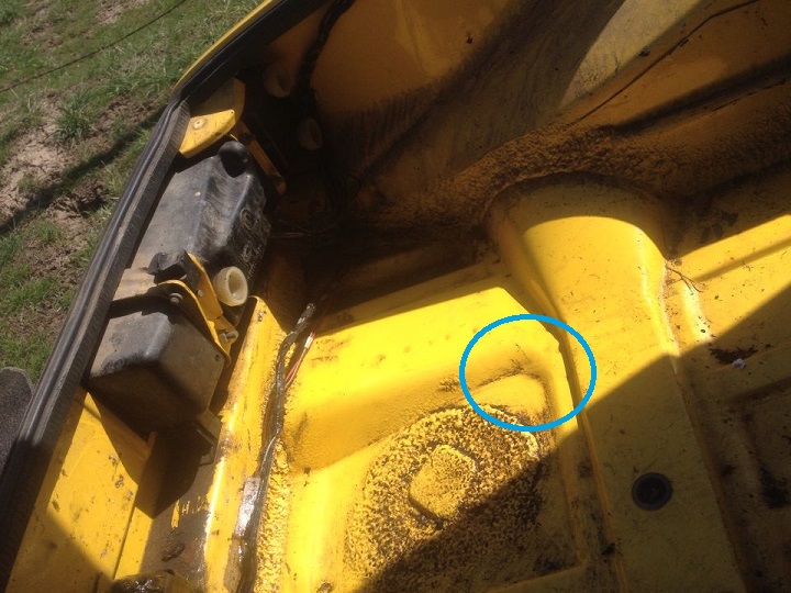 I'm going to focus on these two measurements when I create the triangle piece. 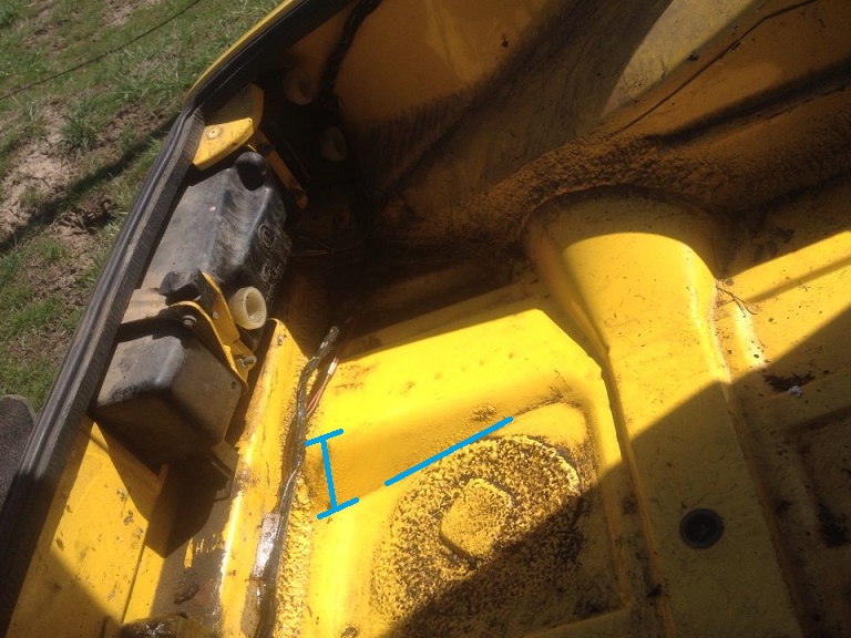 I think I'll contact RD and see if they can chime in and give us there thoughts on the 75-76 modification. |
| sixnotfour |
 Mar 20 2016, 01:50 PM Mar 20 2016, 01:50 PM
Post
#103
|
|
914 Wizard           Group: Members Posts: 10,709 Joined: 12-September 04 From: Life Elevated..planet UT. Member No.: 2,744 Region Association: Rocky Mountains 

|
They will say ...yes that what you need to do....
|
| nihil44 |
 Mar 20 2016, 04:31 PM Mar 20 2016, 04:31 PM
Post
#104
|
|
Member   Group: Members Posts: 157 Joined: 28-January 12 From: Brisbane, Australia Member No.: 14,058 Region Association: None 
|
Cary,
Just took a pic of my '74 floor which has been repaired with the RD panel. The difference is quite marked. Thanks for spotting the difference. I bet I would not have noticed David Attached thumbnail(s) 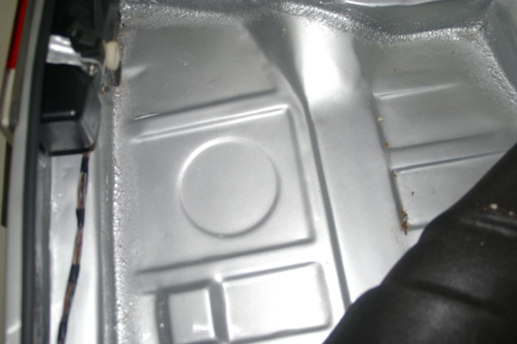
|
| cary |
 Mar 21 2016, 11:22 PM Mar 21 2016, 11:22 PM
Post
#105
|
|
Advanced Member     Group: Members Posts: 3,900 Joined: 26-January 04 From: Sherwood Oregon Member No.: 1,608 Region Association: Pacific Northwest 
|
Modifying RD PP335 to replicate the 75-76 rear trunk : Part #2
I start the day with measuring the portion to be cut out. It's kind of a two step process. First I need to temporarily install the tail light panel supports. This will dictate the finished level of the sloping trunk. 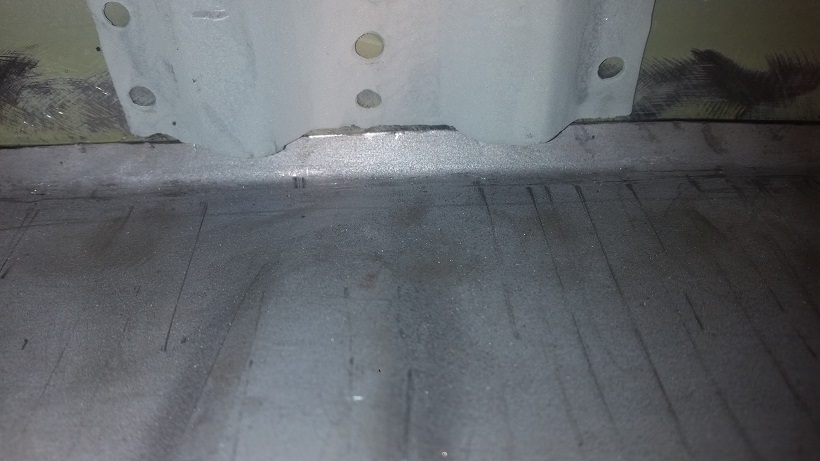 When we slope the trunk we have another geometric problem. The panel then becomes a smidgen short. (IMG:style_emoticons/default/sad.gif) I'll elaborate on Part #3 tomorrow. Here's a shot for a teaser. 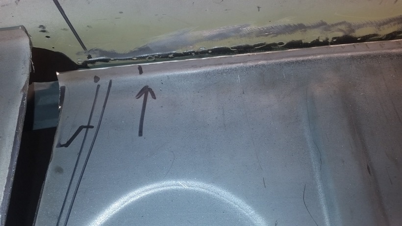 The given is the 2" that is the end width of the triangle patch. 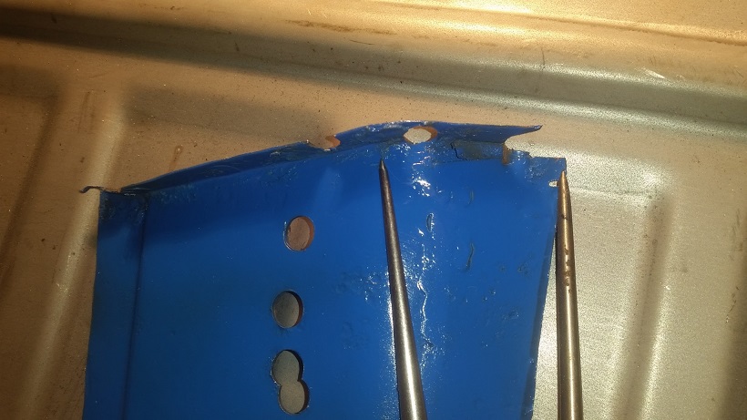 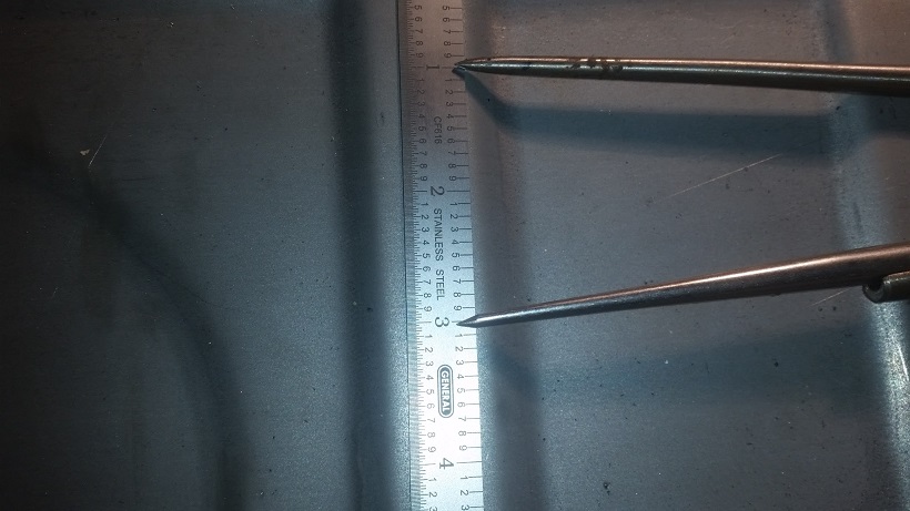 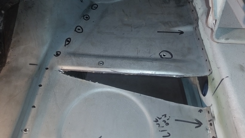 Now on to trimming the panel to go over the side humps. These are a tight fit against the wall. 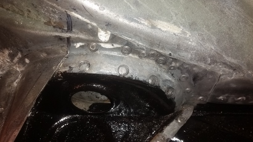 I decided to cut out the two humps first. Then make the money cut last. Right side measurement. 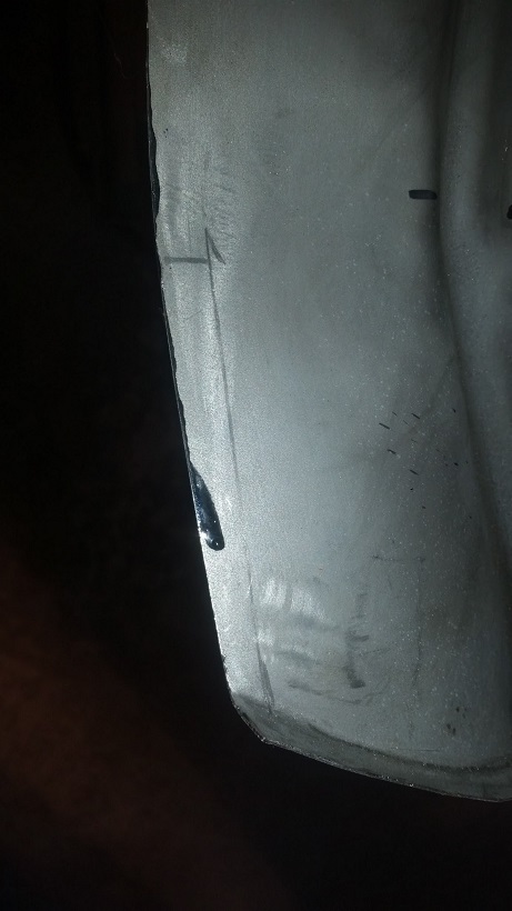 Left side cut out and lined up. 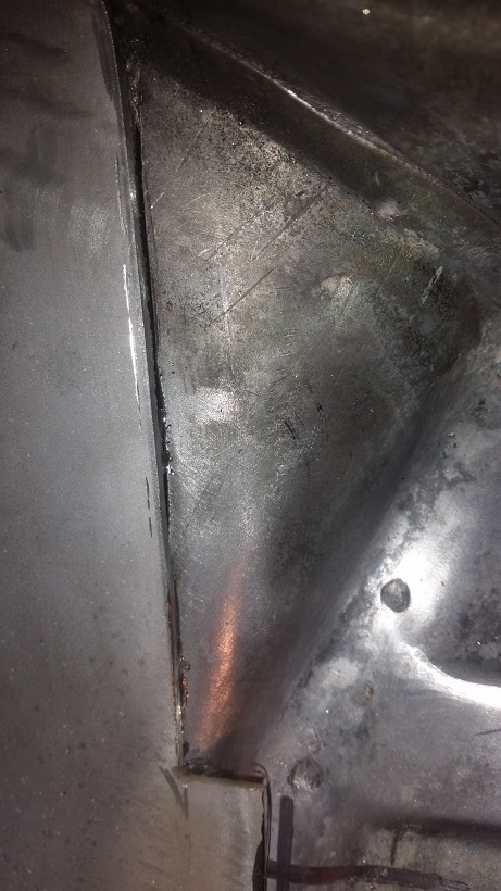 Then I set about making the money cut. This is the long cut along the open section of the transmission mount support. I did it wallpaper hanging style, making a double cut. I held it in place with self tapping screws. I started with the die grinder on the mandrel. I didn't like it, I couldn't feel the lower layer. So I used the air hacksaw, worked great. 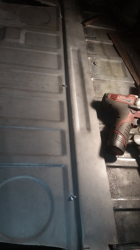 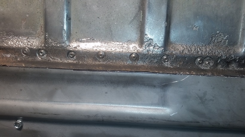 I'll hand the trunk panel off to Super In Law to create the sloped triangles and fabricate the corner extensions/modifications. |
| cary |
 Mar 21 2016, 11:43 PM Mar 21 2016, 11:43 PM
Post
#106
|
|
Advanced Member     Group: Members Posts: 3,900 Joined: 26-January 04 From: Sherwood Oregon Member No.: 1,608 Region Association: Pacific Northwest 
|
I moved on to starting the rear half of the floor pan removal.
It starts with removing the rear floor jack points. 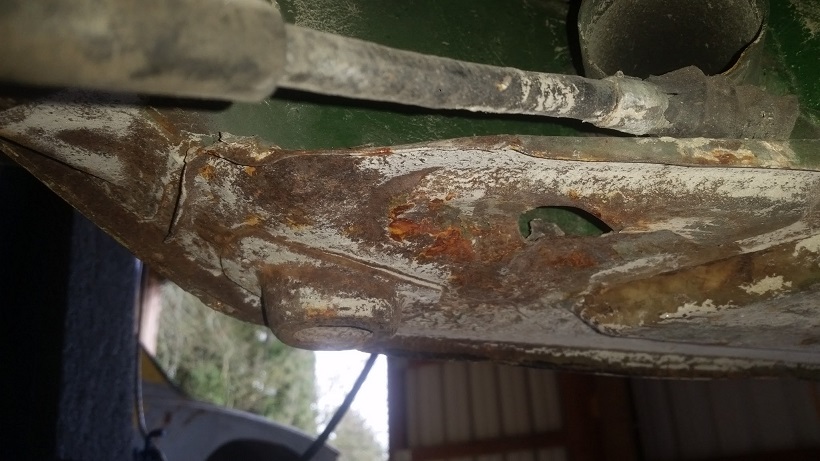 Pleasantly surprised with the condition under the jack points. They'll get OSPHO'd and primered. 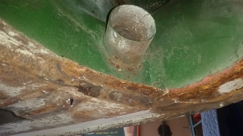 Mark stopped by and brought several boxes new hardware. We decided that we'll need to order 2 new rear floor jack points. I could work them back to presentable. But the metal would be quite fatigued. On a sad note note I did find a double layer hillbilly patch on the right rear of the floor pan. Which is ok to do for a quick cover. But DON'T seam weld over the floor pan spot welds. I'll show some detail on how I'll work around it tomorrow. Punch some new rosette holes and weld them in. 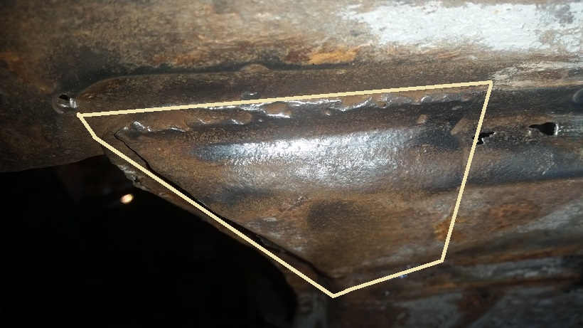 |
| raynekat |
 Mar 22 2016, 11:30 AM Mar 22 2016, 11:30 AM
Post
#107
|
|
Advanced Member     Group: Members Posts: 2,167 Joined: 30-December 14 From: Coeur d'Alene, Idaho Member No.: 18,263 Region Association: Pacific Northwest 
|
Cary....you're cruising.
Well done. I'll be back in the States in late April. Hope to see you and catch up with all you've been doing. |
| Chris H. |
 Mar 22 2016, 11:37 AM Mar 22 2016, 11:37 AM
Post
#108
|
|
Senior Member     Group: Members Posts: 4,053 Joined: 2-January 03 From: Chicago 'burbs Member No.: 73 Region Association: Upper MidWest 
|
....double layer hillbilly patch.... (IMG:style_emoticons/default/lol-2.gif) phrase of the week! Great work Cary! |
| malcolm2 |
 Mar 22 2016, 01:31 PM Mar 22 2016, 01:31 PM
Post
#109
|
|
Advanced Member     Group: Members Posts: 2,747 Joined: 31-May 11 From: Nashville Member No.: 13,139 Region Association: South East States 
|
I did not see the heat shield that attaches to the btm of the trunk panel. It seems that it would be easy to weld while the trunk panel is on the bench vs upside down when installed.
|
| cary |
 Mar 22 2016, 01:35 PM Mar 22 2016, 01:35 PM
Post
#110
|
|
Advanced Member     Group: Members Posts: 3,900 Joined: 26-January 04 From: Sherwood Oregon Member No.: 1,608 Region Association: Pacific Northwest 
|
run domed allen screws in the trunk under the mat. Mark's heat shield is in a cart ready to be blasted when I get set up outside again. The shield has the stand offs still on it. Stand offs will be welded to the trunk floor. Heat shield will bolt to the stand offs. edited 4/5/16 |
| cary |
 Mar 22 2016, 07:58 PM Mar 22 2016, 07:58 PM
Post
#111
|
|
Advanced Member     Group: Members Posts: 3,900 Joined: 26-January 04 From: Sherwood Oregon Member No.: 1,608 Region Association: Pacific Northwest 
|
Measure ten times then cut .............. fairly simple pattern. Only issue was the flange against the tail light panel.
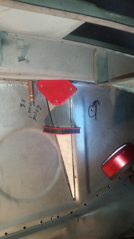 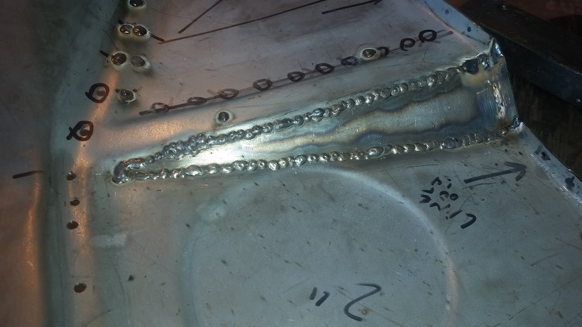 It's always nice to weld new 18 gauge to 18 gauge. (IMG:style_emoticons/default/welder.gif) 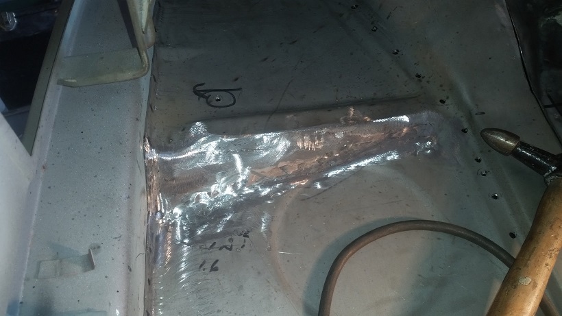 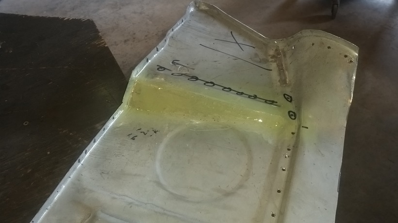 |
| cary |
 Mar 22 2016, 08:20 PM Mar 22 2016, 08:20 PM
Post
#112
|
|
Advanced Member     Group: Members Posts: 3,900 Joined: 26-January 04 From: Sherwood Oregon Member No.: 1,608 Region Association: Pacific Northwest 
|
I learned we have a few more issues when converting to the 75-76 trunk panel.
Here's corner shot of the factory 75-76 trunk panel. You can see the dipped section in the corner. 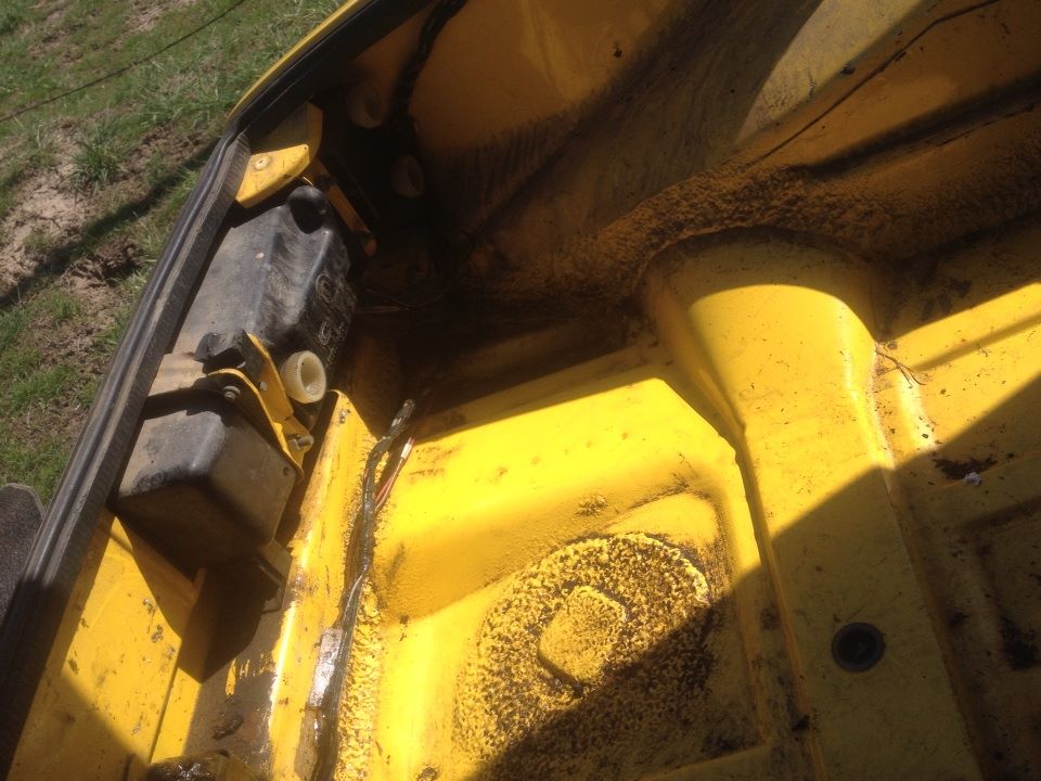 Here's the PP335. 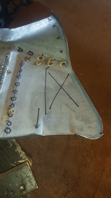 The X is where the dipped section is. The new one is flat. The problem I ran into is I can't make contact with the transmission support in the corner. 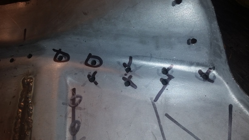 Don't drill the holes I have marked with X's. They had to be refilled. (IMG:style_emoticons/default/mad.gif) I may try it one time after everything is completely welded down. The level is dictated by the hump and the bumper support. I need 1/8 to 3/16 ths. |
| cary |
 Mar 22 2016, 08:44 PM Mar 22 2016, 08:44 PM
Post
#113
|
|
Advanced Member     Group: Members Posts: 3,900 Joined: 26-January 04 From: Sherwood Oregon Member No.: 1,608 Region Association: Pacific Northwest 
|
On Mark's visit he added another item to my list . LOL.
He wants me to transfer the hole plugs from the old trunk panel. (IMG:style_emoticons/default/sawzall-smiley.gif) I'll give the seam sealer a good soaking with brake cleaner in the am. Then we'll get after it with multiple scrapers. Should be a fun challenge .................. 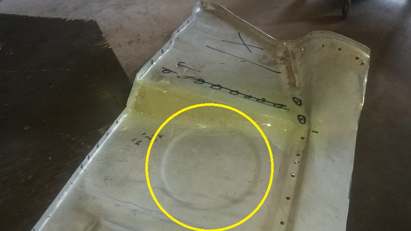 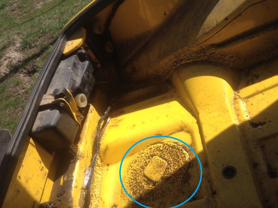 |
| sixnotfour |
 Mar 22 2016, 08:46 PM Mar 22 2016, 08:46 PM
Post
#114
|
|
914 Wizard           Group: Members Posts: 10,709 Joined: 12-September 04 From: Life Elevated..planet UT. Member No.: 2,744 Region Association: Rocky Mountains 

|
Great Job...did not want you to do more work , Butt the end result will be Way Better...weld on...Jeff
|
| sixnotfour |
 Mar 22 2016, 08:47 PM Mar 22 2016, 08:47 PM
Post
#115
|
|
914 Wizard           Group: Members Posts: 10,709 Joined: 12-September 04 From: Life Elevated..planet UT. Member No.: 2,744 Region Association: Rocky Mountains 

|
|
| cary |
 Mar 23 2016, 09:28 PM Mar 23 2016, 09:28 PM
Post
#116
|
|
Advanced Member     Group: Members Posts: 3,900 Joined: 26-January 04 From: Sherwood Oregon Member No.: 1,608 Region Association: Pacific Northwest 
|
When we slope the trunk we have another geometric problem. The panel then becomes a smidgen short.
From Post #105 When we slope the floor it pulls the base of the spot weld flange out from the tail light panel. (IMG:style_emoticons/default/mad.gif) Which will not allow me to rosette that portion of the flange without making an ugly mess. So those portions in the middle will be tacked on the top of the flange. Which won't be seen. They'll be finished with sprayed on seam sealer. 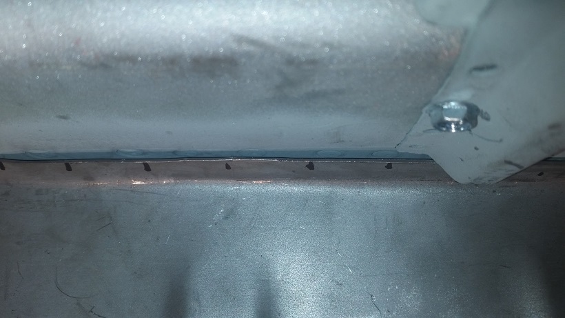 The dark line is the gap. |
| cary |
 Mar 23 2016, 09:43 PM Mar 23 2016, 09:43 PM
Post
#117
|
|
Advanced Member     Group: Members Posts: 3,900 Joined: 26-January 04 From: Sherwood Oregon Member No.: 1,608 Region Association: Pacific Northwest 
|
While I move on to removing the rear portion of the floor pan. Super In Law will be recreating both corners of the trunk. They too have big gaps on the sides and in the corner. So we're going to cut them off and create a new corner.
BEFORE 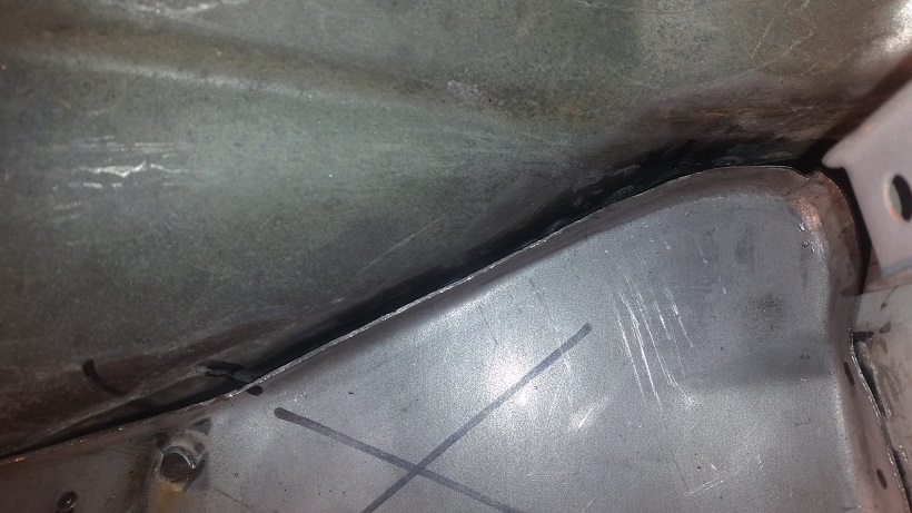 AFTER 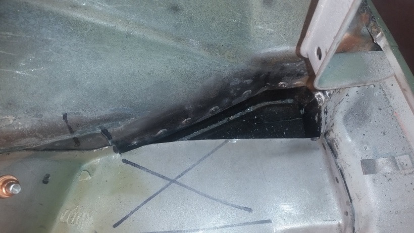 The right side was trimmed and ready to be tacked it. |
| cary |
 Mar 23 2016, 10:20 PM Mar 23 2016, 10:20 PM
Post
#118
|
|
Advanced Member     Group: Members Posts: 3,900 Joined: 26-January 04 From: Sherwood Oregon Member No.: 1,608 Region Association: Pacific Northwest 
|
Onto removing the floor. I like to remove the sides and the middle. Then make two middle cuts leaving me 2-3 inches to work with when removing the welds on the center support and the rear fire walls. I'm all about preserving as much of the floor pan flanges that you can.
I don't need to add any floor pan removal pictures. They've been done many times. Ill only elaborate on the tricky parts. First tricky spot. For some reason they run a couple seam welds right under the inside seat belt bolts on both sides. 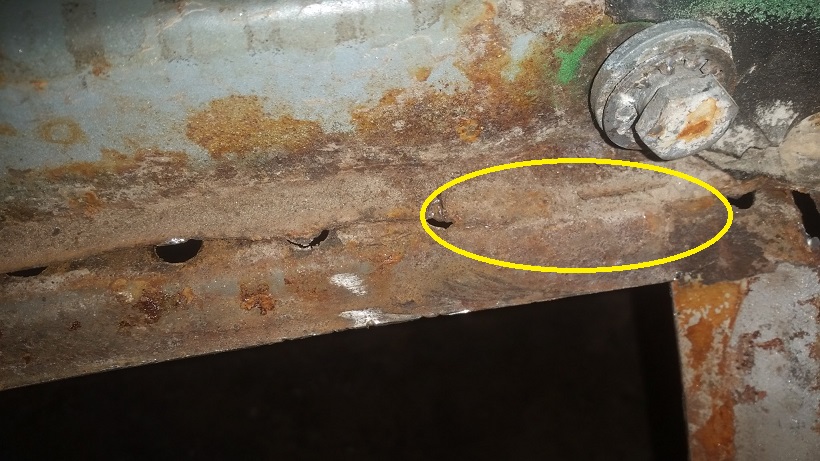 So I cut around the seam welds so I can come back and surgically remove them. 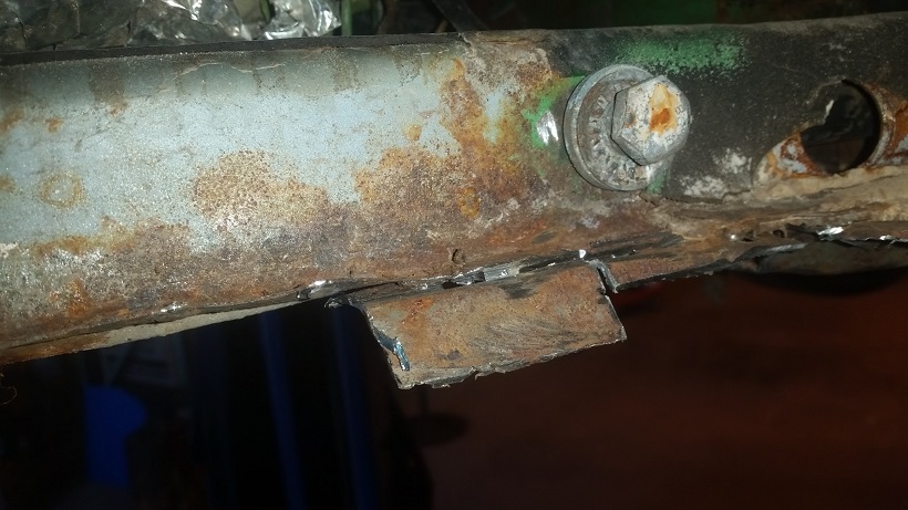 Time for lunch ................ 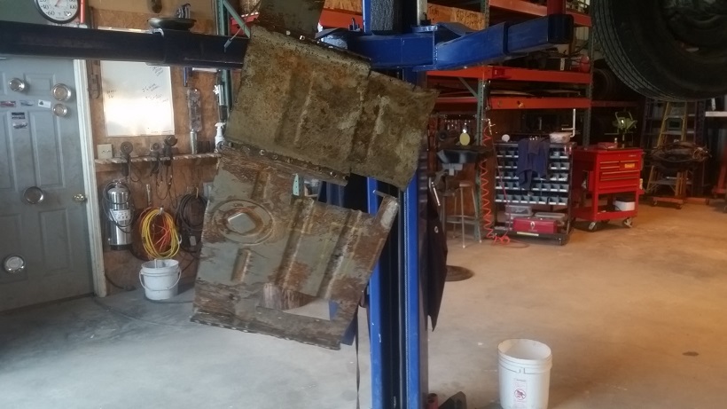 Next tricky spot is the seam welds under the seat adjusters. 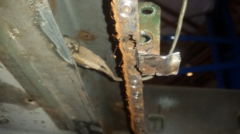 Same program, leave the seam welded portion so it can be surgically removed. Then I remove the e-brake pivot. Pivot pin was bent. Drew alignment marks above to help with installing the replacement. 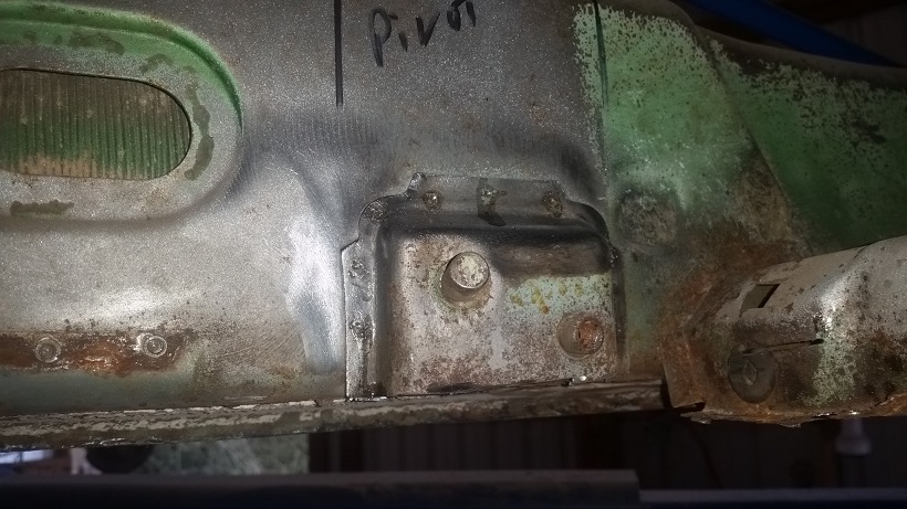 I did find some more rust. The bottom of the left inner firewall has been nibbled on by the worm. (IMG:style_emoticons/default/sawzall-smiley.gif) 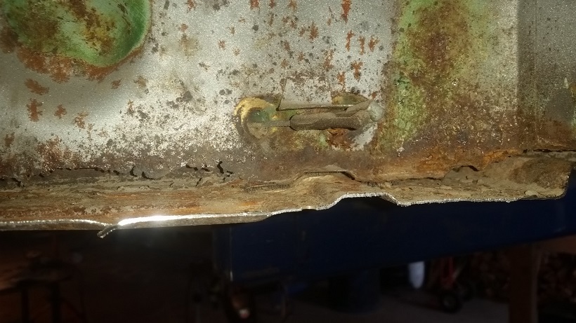 We should be able to patch that bottom portion and flange. Today's scrap pile ............ 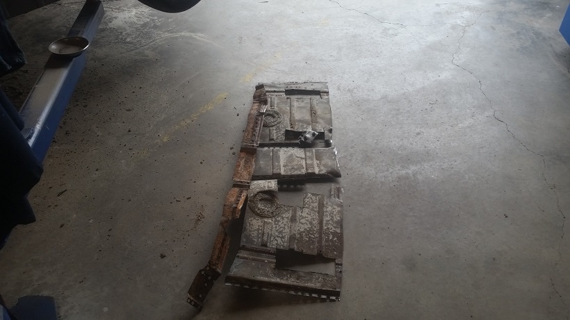 Tomorrow, the remaining portion of the floor under the rear firewall. Could be tricky with the patch that is on the engine side. Long seam weld (IMG:style_emoticons/default/sad.gif) 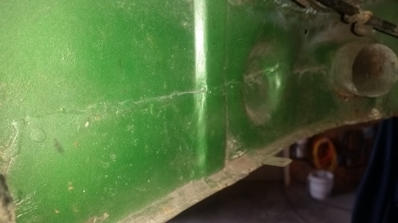 |
| cary |
 Mar 24 2016, 09:44 PM Mar 24 2016, 09:44 PM
Post
#119
|
|
Advanced Member     Group: Members Posts: 3,900 Joined: 26-January 04 From: Sherwood Oregon Member No.: 1,608 Region Association: Pacific Northwest 
|
Onto to finishing up the trunk panel. Here's a shot of one of the new corners we created.
Now we're nice and tight on all sides. We should be able to do rosette welds in all but the corner. Corner has too many seams coming together to get a tight enough fit. That's why its always overfilled with seam sealer. 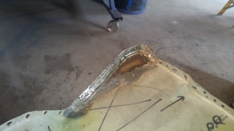 Then on to installing the 75-76 tail light panel support. 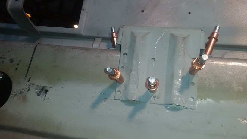 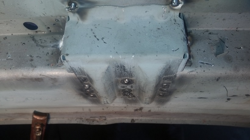 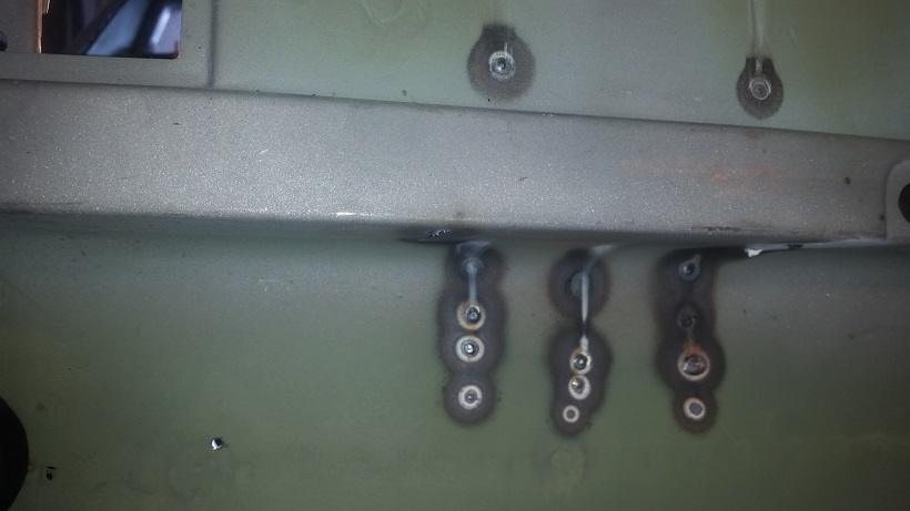 Decided to fulfill Mark's request while we still had the trunk panel on the table. We removed the plugs from the old trunk panel. Chisels, brake cleaner and the heat gun. Then tidied it up with the wire cup brush. I decided to cut up the panel itself and use the old hole as a guide for my air hacksaw. 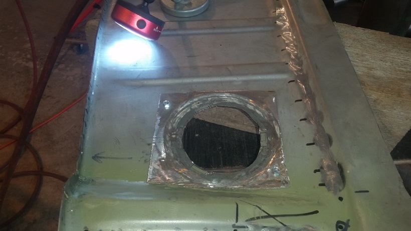 Pictures tell it all ............... Topside 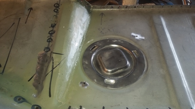 Bottom 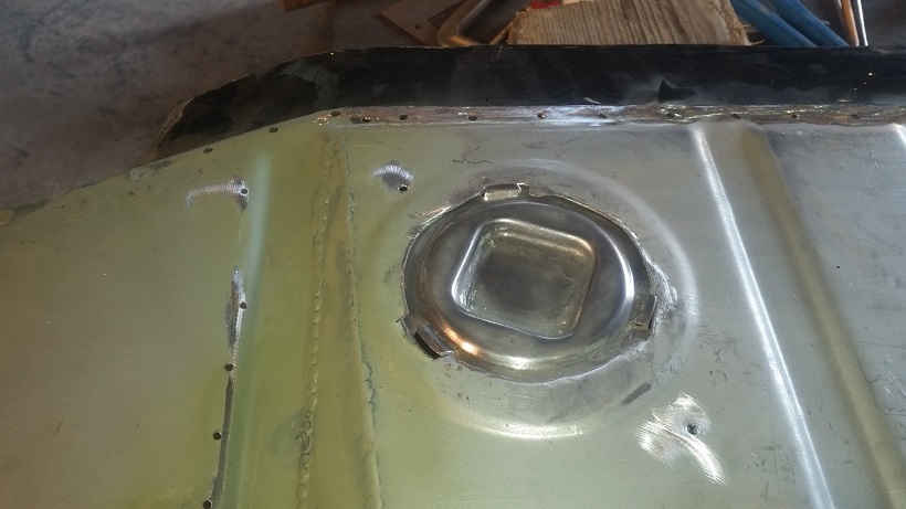 |
| cary |
 Mar 24 2016, 10:01 PM Mar 24 2016, 10:01 PM
Post
#120
|
|
Advanced Member     Group: Members Posts: 3,900 Joined: 26-January 04 From: Sherwood Oregon Member No.: 1,608 Region Association: Pacific Northwest 
|
I start with welding in the poor fitting flange to the tail light panel. (IMG:style_emoticons/default/welder.gif)
Best I could measure when we lowered the trunk floor we added 3/8" to the needed panel length. This shot is from under the car. The yellow line should be tight against the bottom panel. 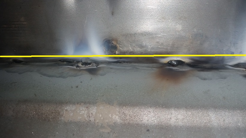 Like I mentioned earlier the back panel would be tack welded. Do not do any aggressive hammer work on the back panel of the trunk. It will make a mess of the tail light panel on the back. 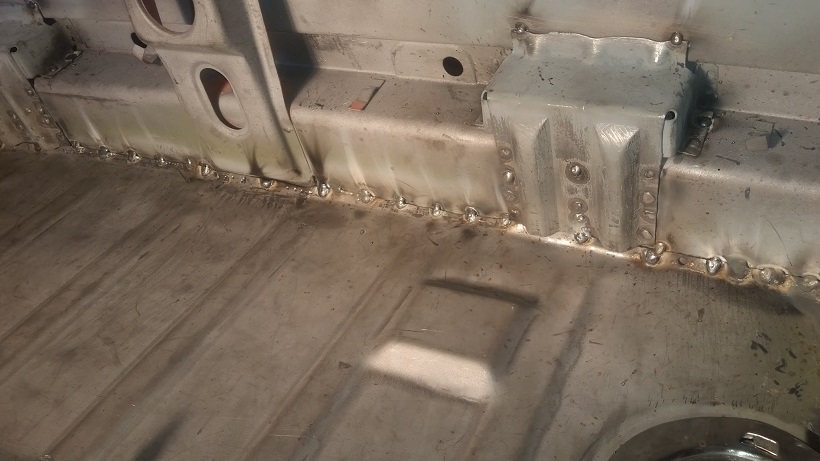 I wish I'd bought 3 or 4 of these to hold the flange tight. https://www.zoro.com/irwin-vise-grip-lockin...275/i/G0317466/ 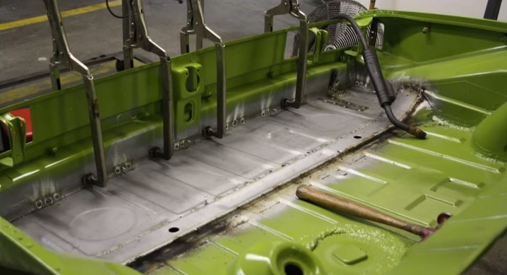 With the 45 degree angle I don't know if they would have worked. Those are the pivot foot model. 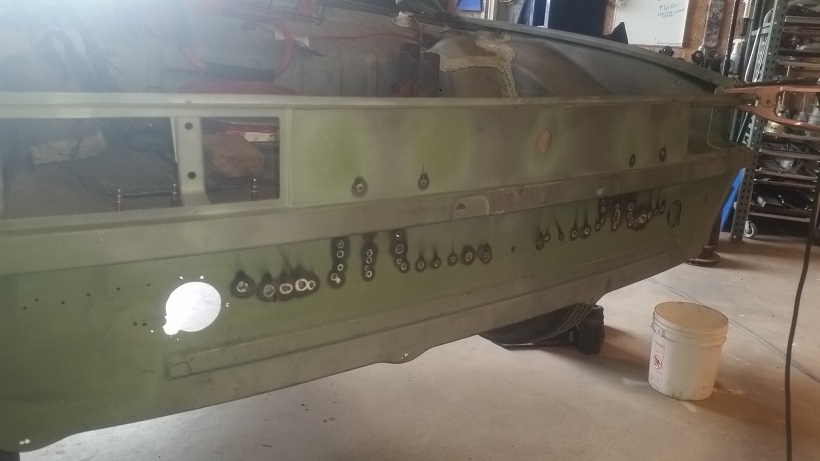 At the end of the day. The inside of the trunk gets seam sealed. And that portion of the tail light panel is under the bumper. |
  |
3 User(s) are reading this topic (3 Guests and 0 Anonymous Users)
0 Members:

|
Lo-Fi Version | Time is now: 18th January 2025 - 08:40 PM |
Invision Power Board
v9.1.4 © 2025 IPS, Inc.


