|
|

|
Porsche, and the Porsche crest are registered trademarks of Dr. Ing. h.c. F. Porsche AG.
This site is not affiliated with Porsche in any way. Its only purpose is to provide an online forum for car enthusiasts. All other trademarks are property of their respective owners. |
|
|
  |
| timothy_nd28 |
 Jun 9 2016, 01:23 PM Jun 9 2016, 01:23 PM
Post
#21
|
|
Advanced Member     Group: Members Posts: 2,299 Joined: 25-September 07 From: IN Member No.: 8,154 Region Association: Upper MidWest 
|
|
| Groosh |
 Jun 10 2016, 01:05 PM Jun 10 2016, 01:05 PM
Post
#22
|
|
Member   Group: Members Posts: 50 Joined: 21-October 11 From: Dexter, MI Member No.: 13,702 Region Association: Upper MidWest |
Adding new parts just confounds the problem. Remove the fuel pump jumper and re-install the old dual relay. When you tested for voltage on pin 10 of the ECU connector, was the ignition switch to on? If so, let's do one thing before continuing with further tests. On the ignition coil, there should be a single wire on the (+) side terminal. Remove this wire, and tape it off. It's bad for the ignition coil and points when doing tests with the ignition key set for on, but the engine not running. After the wire has been removed, we need to measure some voltages at the dual relay. With the meter set to DC, put the black lead on the negative battery post. Now with the red meter lead, probe pin 88z, then 88a and 88b. Report back what you see. This above test is done with the ignition key set to the "on or run" position. Ok. I tried pin 10 again with the switch on but did not read any volts. After taping off the positive lead to the coil, I tested the following with the ignition switch on: 88z - 12 volts 88a - nothing 88b - nothing |
| timothy_nd28 |
 Jun 10 2016, 04:05 PM Jun 10 2016, 04:05 PM
Post
#23
|
|
Advanced Member     Group: Members Posts: 2,299 Joined: 25-September 07 From: IN Member No.: 8,154 Region Association: Upper MidWest 
|
Okay, use one of the jumper wires you just bought from Radio Shack and jump pin 86C on the dual relay to the positive battery terminal. Then recheck for voltages as I described in the earlier step.
|
| Groosh |
 Jun 11 2016, 06:53 AM Jun 11 2016, 06:53 AM
Post
#24
|
|
Member   Group: Members Posts: 50 Joined: 21-October 11 From: Dexter, MI Member No.: 13,702 Region Association: Upper MidWest |
Okay, use one of the jumper wires you just bought from Radio Shack and jump pin 86C on the dual relay to the positive battery terminal. Then recheck for voltages as I described in the earlier step. 86c was already getting proper volts from the ignition switch in the "on" position so I didn't jump it. However I still get no other readings on 88a or 88b. |
| timothy_nd28 |
 Jun 11 2016, 07:15 AM Jun 11 2016, 07:15 AM
Post
#25
|
|
Advanced Member     Group: Members Posts: 2,299 Joined: 25-September 07 From: IN Member No.: 8,154 Region Association: Upper MidWest 
|
Okay, jump pin 85 at the dual relay to the negative battery post. Redo same test as above.
|
| Groosh |
 Jun 11 2016, 10:08 AM Jun 11 2016, 10:08 AM
Post
#26
|
|
Member   Group: Members Posts: 50 Joined: 21-October 11 From: Dexter, MI Member No.: 13,702 Region Association: Upper MidWest |
|
| timothy_nd28 |
 Jun 11 2016, 11:54 AM Jun 11 2016, 11:54 AM
Post
#27
|
|
Advanced Member     Group: Members Posts: 2,299 Joined: 25-September 07 From: IN Member No.: 8,154 Region Association: Upper MidWest 
|
What about pin 10 at the ECU?
|
| Groosh |
 Jun 11 2016, 12:14 PM Jun 11 2016, 12:14 PM
Post
#28
|
|
Member   Group: Members Posts: 50 Joined: 21-October 11 From: Dexter, MI Member No.: 13,702 Region Association: Upper MidWest |
|
| timothy_nd28 |
 Jun 11 2016, 01:30 PM Jun 11 2016, 01:30 PM
Post
#29
|
|
Advanced Member     Group: Members Posts: 2,299 Joined: 25-September 07 From: IN Member No.: 8,154 Region Association: Upper MidWest 
|
We need to make sure that you are indeed probing pin 10 of the ECU connector. So, put your meter on a low resistance setting. Then put one meter lead on the negative (-) terminal of the ignition coil, put the other lead on what you think is pin 1 of the ECU connector, you should get 0 ohms
|
| Groosh |
 Jun 11 2016, 02:02 PM Jun 11 2016, 02:02 PM
Post
#30
|
|
Member   Group: Members Posts: 50 Joined: 21-October 11 From: Dexter, MI Member No.: 13,702 Region Association: Upper MidWest |
We need to make sure that you are indeed probing pin 10 of the ECU connector. So, put your meter on a low resistance setting. Then put one meter lead on the negative (-) terminal of the ignition coil, put the other lead on what you think is pin 1 of the ECU connector, you should get 0 ohms Well, I did get 0 ohms. As far as me doing it right? I hope so. |
| timothy_nd28 |
 Jun 11 2016, 02:22 PM Jun 11 2016, 02:22 PM
Post
#31
|
|
Advanced Member     Group: Members Posts: 2,299 Joined: 25-September 07 From: IN Member No.: 8,154 Region Association: Upper MidWest 
|
We might as well check some other wires, I'm starting to doubt your wiring harness.
Key on, wire still off (and taped) the ignition coil, jumper wire still on pin 85 (dual relay) to negative battery terminal, meter set for DC volts, put one meter lead on the negative battery post. Now, make sure you still have 12vdc on pins 88a and 88b of the dual relay, if so you can continue. Leave one meter lead on the negative battery post. Put the other meter lead on pin 14 of the ECU connector, you should get 12vdc. If so, move the meter lead from pin 14 and place it on pin 15, again you should see 12vdc. Move the meter lead from pin 15, and place it on pin 32, you should see 12vdc. Finally, move the meter lead from pin 32 and move it to pin 33, you should see 12vdc. This tests the continuity of the wiring to the fuel injector, continuity of the injector itself, continuity of the wires leaving the injector to the resistor pack, continuity of the resistors. This is a good test, kinda checks everything. After all that, put one meter lead on the positive battery post. With the other meter lead, probe pins: 5,16, and 17 on the ecu connector. You should have 12volts on each pin. If all that passes, recheck pin 10 on the ecu connector for 12vdc. Pin 10 is a very important pin. This pin supplies power to the ECU, no power to this pin will keep the computer off. |
| Groosh |
 Jun 12 2016, 11:24 AM Jun 12 2016, 11:24 AM
Post
#32
|
|
Member   Group: Members Posts: 50 Joined: 21-October 11 From: Dexter, MI Member No.: 13,702 Region Association: Upper MidWest |
We might as well check some other wires, I'm starting to doubt your wiring harness. Key on, wire still off (and taped) the ignition coil, jumper wire still on pin 85 (dual relay) to negative battery terminal, meter set for DC volts, put one meter lead on the negative battery post. Now, make sure you still have 12vdc on pins 88a and 88b of the dual relay, if so you can continue. Leave one meter lead on the negative battery post. Put the other meter lead on pin 14 of the ECU connector, you should get 12vdc. If so, move the meter lead from pin 14 and place it on pin 15, again you should see 12vdc. Move the meter lead from pin 15, and place it on pin 32, you should see 12vdc. Finally, move the meter lead from pin 32 and move it to pin 33, you should see 12vdc. This tests the continuity of the wiring to the fuel injector, continuity of the injector itself, continuity of the wires leaving the injector to the resistor pack, continuity of the resistors. This is a good test, kinda checks everything. After all that, put one meter lead on the positive battery post. With the other meter lead, probe pins: 5,16, and 17 on the ecu connector. You should have 12volts on each pin. If all that passes, recheck pin 10 on the ecu connector for 12vdc. Pin 10 is a very important pin. This pin supplies power to the ECU, no power to this pin will keep the computer off. Shoot. I was doing it wrong before and now have myself straightened out. Here is where I'm getting 12vdc with the key "on" - 10 pin - 15 pin - 32 pin - 5, 16, 17 Not getting volts on: - 14, 33 |
| timothy_nd28 |
 Jun 12 2016, 07:25 PM Jun 12 2016, 07:25 PM
Post
#33
|
|
Advanced Member     Group: Members Posts: 2,299 Joined: 25-September 07 From: IN Member No.: 8,154 Region Association: Upper MidWest 
|
Pin 14 and 33 are two of the four injectors. Disconnect the resistor pack and post a picture
|
| timothy_nd28 |
 Jun 12 2016, 07:43 PM Jun 12 2016, 07:43 PM
Post
#34
|
|
Advanced Member     Group: Members Posts: 2,299 Joined: 25-September 07 From: IN Member No.: 8,154 Region Association: Upper MidWest 
|
The resistor pack should look similar to this:
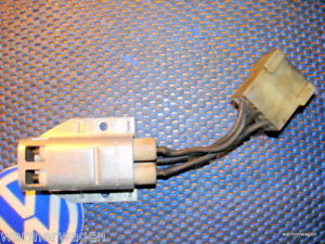 Once you disconnect the connector to this device, set your meter for resistance and put one meter lead at the center pin (on the connector leading to the resistor pack). Probe the outside pins with the other meter lead. You should get a pretty low resistance on those four pins. These wires are frail and tend to break. It would be nice to rule this out before diving into a more complicated test procedure. |
| Groosh |
 Jun 13 2016, 07:02 AM Jun 13 2016, 07:02 AM
Post
#35
|
|
Member   Group: Members Posts: 50 Joined: 21-October 11 From: Dexter, MI Member No.: 13,702 Region Association: Upper MidWest |
The resistor pack should look similar to this:  Once you disconnect the connector to this device, set your meter for resistance and put one meter lead at the center pin (on the connector leading to the resistor pack). Probe the outside pins with the other meter lead. You should get a pretty low resistance on those four pins. These wires are frail and tend to break. It would be nice to rule this out before diving into a more complicated test procedure. The wires look good. The resistance is even across all four pins. Yes, I kick it old school with my father's old meter. Attached thumbnail(s) 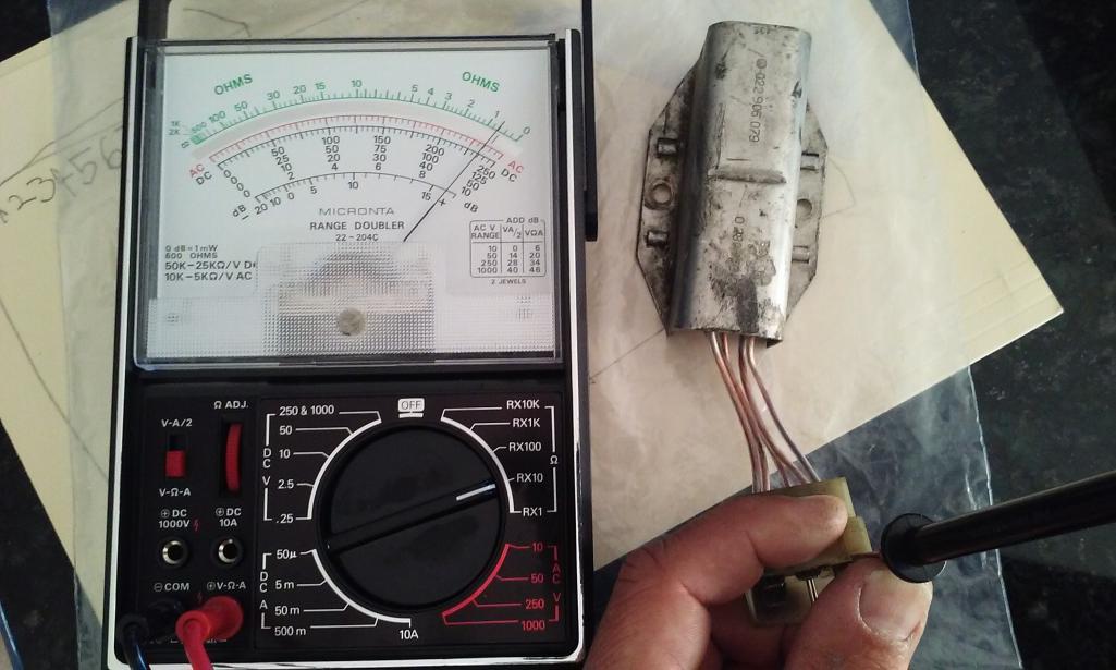
|
| timothy_nd28 |
 Jun 13 2016, 10:13 AM Jun 13 2016, 10:13 AM
Post
#36
|
|
Advanced Member     Group: Members Posts: 2,299 Joined: 25-September 07 From: IN Member No.: 8,154 Region Association: Upper MidWest 
|
Old meters like that are awesome! Go ahead and reinstall the resistor pack, then try re-seating each fuel injector connector. So, remove the 2 pin electrical connector from a fuel injector, then push it back on. Do this 13 times for each fuel injectors' connector. After all this is done, and assuming that jumper is still on pin 85 of the dual relay and the ignition key is on,,put one meter lead on the negative battery post. With the other meter lead, probe pins 14,15,32,33 to see if they have 12volts, more importantly does pin 14 and 33 now have voltage after reseating the fuel injector connectors?
If the above instructions fail to remedy pins 14 and 33 then lets continue. We need to know what injectors correlate to pins 14 and 33. To find this out, we can use the injectors that do work, pins 15 and 32. Put your meter lead on pin 15 and with the same test conditions as the paragraph above, you should get 12volts. Start by unplugging one fuel injector at a time while watching your meter. If the 12volts drops out when unplugging, then that injector matches up with pin 15. If 12volts is still present after unplugging one fuel injector, simply plug that connector back in and move onto the next fuel injector connector. Rinse and repeat till you find that one injector that makes pin 15 go dead. Repeat the same test but put the meter lead in pin 32, find that other good injector. Once you find the two good injectors, we now know the two problem injectors. With the offending fuel injectors, go ahead and remove the connectors for those two. It will be hard to probe these pins with your meter, you may need to fashion a paperclip at the end of your meter lead. Ok, with the ignition switch set to on and your jumper still on the dual relay, put one meter lead on the negative battery post. We are measuring for 12volts. Probe both pins of each injector harness connector. Of the two pins, only one will show 12volts while the other pin will read nothing, do this for both bad injectors. |
| Groosh |
 Jun 20 2016, 07:17 AM Jun 20 2016, 07:17 AM
Post
#37
|
|
Member   Group: Members Posts: 50 Joined: 21-October 11 From: Dexter, MI Member No.: 13,702 Region Association: Upper MidWest |
Old meters like that are awesome! Go ahead and reinstall the resistor pack, then try re-seating each fuel injector connector. So, remove the 2 pin electrical connector from a fuel injector, then push it back on. Do this 13 times for each fuel injectors' connector. After all this is done, and assuming that jumper is still on pin 85 of the dual relay and the ignition key is on,,put one meter lead on the negative battery post. With the other meter lead, probe pins 14,15,32,33 to see if they have 12volts, more importantly does pin 14 and 33 now have voltage after reseating the fuel injector connectors? If the above instructions fail to remedy pins 14 and 33 then lets continue. We need to know what injectors correlate to pins 14 and 33. To find this out, we can use the injectors that do work, pins 15 and 32. Put your meter lead on pin 15 and with the same test conditions as the paragraph above, you should get 12volts. Start by unplugging one fuel injector at a time while watching your meter. If the 12volts drops out when unplugging, then that injector matches up with pin 15. If 12volts is still present after unplugging one fuel injector, simply plug that connector back in and move onto the next fuel injector connector. Rinse and repeat till you find that one injector that makes pin 15 go dead. Repeat the same test but put the meter lead in pin 32, find that other good injector. Once you find the two good injectors, we now know the two problem injectors. With the offending fuel injectors, go ahead and remove the connectors for those two. It will be hard to probe these pins with your meter, you may need to fashion a paperclip at the end of your meter lead. Ok, with the ignition switch set to on and your jumper still on the dual relay, put one meter lead on the negative battery post. We are measuring for 12volts. Probe both pins of each injector harness connector. Of the two pins, only one will show 12volts while the other pin will read nothing, do this for both bad injectors. Well go figure. After the car sat for almost a week things tested out differently. I did the pull reset 13x on the fuel injectors: - 32 is cylinder 2 and gets volts at the 32 pin - 33 is cylinder 3 and gets volts at the 33 pin - 14 no volts at pin - injector harness gets 12 volts - 15 no volts at pin - injector harness gets 12 volts |
| timothy_nd28 |
 Jun 20 2016, 08:18 AM Jun 20 2016, 08:18 AM
Post
#38
|
|
Advanced Member     Group: Members Posts: 2,299 Joined: 25-September 07 From: IN Member No.: 8,154 Region Association: Upper MidWest 
|
For injectors 4 and 1, is this 12volts at the fuel injector connector? If so, test the resistance across the two pins on the fuel injector itself.
|
| Groosh |
 Jun 20 2016, 09:13 AM Jun 20 2016, 09:13 AM
Post
#39
|
|
Member   Group: Members Posts: 50 Joined: 21-October 11 From: Dexter, MI Member No.: 13,702 Region Association: Upper MidWest |
For injectors 4 and 1, is this 12volts at the fuel injector connector? If so, test the resistance across the two pins on the fuel injector itself. Yes. Injectors 1 and 4 get 12 volts at the injector connector. The resistance across all four injectos tests even. Attached thumbnail(s) 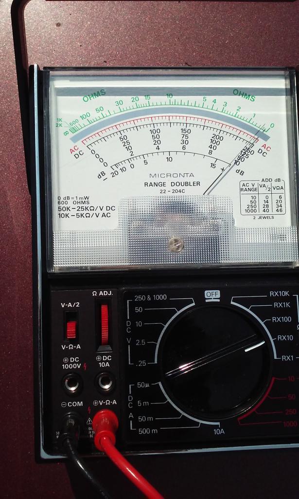
|
| timothy_nd28 |
 Jun 20 2016, 09:54 AM Jun 20 2016, 09:54 AM
Post
#40
|
|
Advanced Member     Group: Members Posts: 2,299 Joined: 25-September 07 From: IN Member No.: 8,154 Region Association: Upper MidWest 
|
Since the injectors all have continuity, the problem lies in a short wire run from the injector's connector to the ECU connector. I highlighted a red box that illustrates the problem area
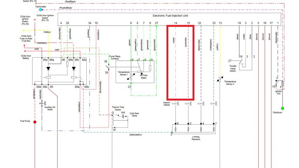 Since you already tested the FI connector of the two failed injectors, and confirmed that you have 12 volts sitting at one of the two pins, confirms that the dual relay is sending voltage thru the resistor pack and is making its way to the fuel injector. Missing voltage at the ECU pins 14 and 15 tells me that there is a break in a wire or a bad connection at one of the connectors. You can remove the fuel injector connector and reconfirm that you do indeed have 12 volts present on one of the two pins. The other dead pin, you can check the resistance of that pin to the ECU connector, which will be either pin 14 or 15. You should read 0 ohms, but since you are not getting voltage on pins 14 or 15, you may read a high resistance. I bet if you were to jiggle the harness while measuring resistance, you may see things change with your meter. Be extra observant at the two failed injectors, look at the wires and pins at the injector connector. Same thing for pins 14 and 15 at the ECU connector. After all that, you have 3 options. Send your injection harness off to Jeff Bowlsby for repair, or buy a known good used one, or if you are up for it; get a razor blade and split the outer casing of the injection harness and find pin 14/15 wires and repair it yourself. |
  |
1 User(s) are reading this topic (1 Guests and 0 Anonymous Users)
0 Members:

|
Lo-Fi Version | Time is now: 2nd April 2025 - 11:40 PM |
Invision Power Board
v9.1.4 © 2025 IPS, Inc.


