|
|

|
Porsche, and the Porsche crest are registered trademarks of Dr. Ing. h.c. F. Porsche AG.
This site is not affiliated with Porsche in any way. Its only purpose is to provide an online forum for car enthusiasts. All other trademarks are property of their respective owners. |
|
|
  |
| bondo |
 Apr 11 2005, 09:15 PM Apr 11 2005, 09:15 PM
Post
#21
|
||
|
Practicing my perpendicular parking     Group: Members Posts: 4,277 Joined: 19-April 03 From: Los Osos, CA Member No.: 587 Region Association: Central California |
I just turn one wheel with my hands, and hold the other wheel from turning with my feet (IMG:http://www.914world.com/bbs2/html/emoticons/smile.gif) |
||
| bandjoey |
 Nov 11 2010, 09:35 PM Nov 11 2010, 09:35 PM
Post
#22
|
|
bandjoey     Group: Members Posts: 4,934 Joined: 26-September 07 From: Bedford Tx Member No.: 8,156 Region Association: Southwest Region |
After reading this a few times and having it explained a few times, and still being the un-mechanical numskull I am, I had to draw a picture. NOW it makes sense. Rock close and Adjust Open. I know you mechanics will just laugh, but someday I'll catch on. (IMG:style_emoticons/default/biggrin.gif)
Attached thumbnail(s) 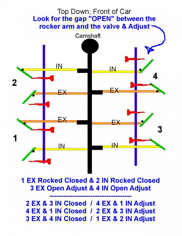
|
| bmtrnavsky |
 Nov 11 2010, 11:32 PM Nov 11 2010, 11:32 PM
Post
#23
|
|
Member   Group: Members Posts: 355 Joined: 20-October 07 From: Longview, TX Member No.: 8,245 Region Association: Southwest Region |
Just curious, but how is this different with hydraulic lifters?
|
| VaccaRabite |
 Nov 12 2010, 08:06 AM Nov 12 2010, 08:06 AM
Post
#24
|
|
En Garde!           Group: Admin Posts: 13,723 Joined: 15-December 03 From: Dallastown, PA Member No.: 1,435 Region Association: MidAtlantic Region 
|
After reading this a few times and having it explained a few times, and still being the un-mechanical numskull I am, I had to draw a picture. NOW it makes sense. Rock close and Adjust Open. I know you mechanics will just laugh, but someday I'll catch on. (IMG:style_emoticons/default/biggrin.gif) Err... You may need to think on this a bit more. A few things that may help. 1) a valves natural state (the state that it spends most of its time) is CLOSED. You MUST adjust a valve when it is closed. You CAN NOT EVER adjust a valve when it is open. 2) reread number 1. A closed valve is a valve that is sealed to the head, not letting fuel in or exhaust out. A valve will stay closed until it is acted on by the pushrod forcing the rocker to open the valve. An open valve is a valve being pushed open by the pushrods to allow gasses into or out of the heads. It does not refer to the gap (that you usually can not see as it is VERY small and may not exist at all if your adjustments are off) between the adjuster foot and the valve stem. Lets look at the first line of the sequence: #2 Ex & #3 In #4 Ex & #1 In First, lets do a little grouping. If you can remember grade school algebra, this may help: ROCK(#2 Ex & #3 In) = ADJUST(#4 Ex & #1 In) When #2Ex & #3in are being rocked, they are being forced open by the rockers. This means that #4 Ex & #1 In are CLOSED and can be adjusted. For each line, the grouping is the same. the first two valves are being ROCKED OPEN and the second pair of valves are CLOSED and can be adjusted. Also, a picture from the top of the car (even a correct one) will not help you much when you are doing this. When you adjust your valves you are under the car, and need to know what everything is going to look like from under the vehicle - not from on top of it. Does this make sense? Zach |
| Root_Werks |
 Nov 12 2010, 08:10 AM Nov 12 2010, 08:10 AM
Post
#25
|
|
Village Idiot      Group: Members Posts: 8,654 Joined: 25-May 04 From: About 5NM from Canada Member No.: 2,105 Region Association: Pacific Northwest 
|
I must be the only one left who uses TDC and adjusts both intake AND exhaust valves! (IMG:style_emoticons/default/yikes.gif)
|
| jaxdream |
 Nov 12 2010, 08:56 AM Nov 12 2010, 08:56 AM
Post
#26
|
|
Senior Member    Group: Members Posts: 974 Joined: 8-July 08 From: North Central Tennessee Member No.: 9,270 Region Association: South East States |
After reading this a few times and having it explained a few times, and still being the un-mechanical numskull I am, I had to draw a picture. NOW it makes sense. Rock close and Adjust Open. I know you mechanics will just laugh, but someday I'll catch on. (IMG:style_emoticons/default/biggrin.gif) This could be a great chart , however , the Intake valves are on the inside ( middle ) position of the head , the Exhaust valves are on the outside ( outter ends ) of the heads , also it needs to have the rocking / adjust seqences in the order of the Capt'n 's list . That would be a great chart . Don't mean to mash any toes , this seems to be a topic of confusion. Dude recheck you art work ( pretty damn good ) for correct valve positions. Jack / Jaxdream |
| tomeric914 |
 Nov 12 2010, 09:09 AM Nov 12 2010, 09:09 AM
Post
#27
|
|
One Lap of America in a 914!    Group: Members Posts: 1,266 Joined: 25-May 08 From: Syracuse, NY Member No.: 9,101 Region Association: North East States 
|
I must be the only one left who uses TDC and adjustes both intake AND exhaust valves! (IMG:style_emoticons/default/yikes.gif) Nope. I use the TDC method as well. http://www.914world.com/bbs2/index.php?sho...109753&st=0 |
| SLITS |
 Nov 12 2010, 10:08 AM Nov 12 2010, 10:08 AM
Post
#28
|
|
"This Utah shit is HARSH!"           Group: Benefactors Posts: 13,602 Joined: 22-February 04 From: SoCal Mountains ... Member No.: 1,696 Region Association: None  |
Gad .... it's butt simple on a /4 .... one down (open fully for the mechanically disadvantaged), adjust it partner on the other side of the engine. You could be (IMG:style_emoticons/default/drunk.gif) and still do it.
Now, a /6 .... that's another story. |
| realred914 |
 Nov 12 2010, 11:17 AM Nov 12 2010, 11:17 AM
Post
#29
|
|
Senior Member    Group: Retired Members Posts: 1,086 Joined: 1-April 10 From: california Member No.: 11,541 Region Association: None |
that was a complicated procedure,
more simply would be to set the engine to top dead center, valves closed for each piston via the pully mark and using teh rotor as referance as to which one is TDC valve closed and adjust that cylinders vlaves all at once. less complicated no table to refer to, just do it! 1 ex, 1 in then rotate 2 ex, 2 in, then rotate, 3 ex, 3 in, then rotate, 4 ex, 4 in, done. |
| bandjoey |
 Nov 12 2010, 04:46 PM Nov 12 2010, 04:46 PM
Post
#30
|
|
bandjoey     Group: Members Posts: 4,934 Joined: 26-September 07 From: Bedford Tx Member No.: 8,156 Region Association: Southwest Region |
I agree with all of you. Glad we do. (IMG:style_emoticons/default/biggrin.gif)
I'm a visual mechanic and I think we mean the same thing but the using one word with different meaning. Herein is the confusion of past. Reread some of the old ?? posts and this is what I see. You say OPEN and as a mechanic mean OPEN VALVE. I say OPEN as a non mechanic I'm looking at the rocker arm not touching the valve stem - - the CLOSED VALVE side with an opening between the valve stem and the rocker. So, with this update... When the VALVE is OPEN, the rocker is pushed out and jammed up touching the valve stem...and cannot be adjusted. Reverse sides and adjust. Am I seeing the light? Attached thumbnail(s) 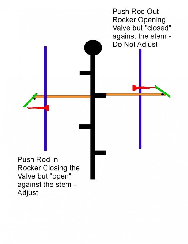
|
| Tom |
 Nov 12 2010, 05:09 PM Nov 12 2010, 05:09 PM
Post
#31
|
|
Advanced Member     Group: Members Posts: 2,139 Joined: 21-August 05 From: Port Orchard, WA 98367 Member No.: 4,626 Region Association: None |
Bill,
Yep, you have it now! Hope the adjustment goes OK for you. Let us know. Tom |
| realred914 |
 Nov 12 2010, 06:00 PM Nov 12 2010, 06:00 PM
Post
#32
|
|
Senior Member    Group: Retired Members Posts: 1,086 Joined: 1-April 10 From: california Member No.: 11,541 Region Association: None |
I agree with all of you. Glad we do. (IMG:style_emoticons/default/biggrin.gif) I'm a visual mechanic and I think we mean the same thing but the using one word with different meaning. Herein is the confusion of past. Reread some of the old ?? posts and this is what I see. You say OPEN and as a mechanic mean OPEN VALVE. I say OPEN as a non mechanic I'm looking at the rocker arm not touching the valve stem - - the CLOSED VALVE side with an opening between the valve stem and the rocker. So, with this update... When the VALVE is OPEN, the rocker is pushed out and jammed up touching the valve stem...and cannot be adjusted. Reverse sides and adjust. Am I seeing the light? this insantity is givening me a head ache (IMG:style_emoticons/default/headbang.gif) lets just skip all of this open, closed, up, down all around secret decoder ring sequence stuff!!!! (IMG:style_emoticons/default/headbang.gif) (IMG:style_emoticons/default/headbang.gif) Please set the engine to top dead center on #1 piston(use the dizzie roter to tell you where your at tdc #1 the rotor will point towards that plug wire), then use the pulley mark to line up the top dead center for piston #1) now you can adjust BOTH valves for piston #1. Next rotate engine back towards the #2 piston TDC. The dizzie rotor will turn 1/4 turn (90 degrees) This will require a one HALF a crank shaft / pulley rotation, (180 degrees), then line up TDC on the pully (you have to make the mark, at 180 degrees opposite of the factory tdc mark) and now adjust BOTH #2 piston valves. do same proceedure for #3 and #4 pistons valves, rotate the engine 180 degrees to move on to each piston, line up the tdc mark on pulley, and adjust BOTH valves for that piston. do not confuse the the other timing marks with the tdc mark (0 degree mark) doing it for near forty years that way. one other thing, if you are rotating the tire to turn the engine, you can lay back and observe the rocker arms move, and you can see that approaching the tdc for each piston, BOTH arms will remain at a maximum extension for some good bit of the rotation. so long as you in this "window" of no more change in lift (ie no more rocker movement whilest cam is turned) you are ready to adjust the valve. Also.....always make note of the pre-adjustment reading of EACH valve, make adjustments as needed and record that also. This historical info will be helpfull in finding problem valves if they creep up (and creep in clearance repeatadly) so learn to record this data in you maintance log. have fun (IMG:style_emoticons/default/smash.gif) (IMG:style_emoticons/default/smash.gif) (IMG:style_emoticons/default/smash.gif) (IMG:style_emoticons/default/smash.gif) (IMG:style_emoticons/default/chowtime.gif) |
| glens67 |
 Nov 12 2010, 06:28 PM Nov 12 2010, 06:28 PM
Post
#33
|
|
Newbie  Group: Members Posts: 35 Joined: 13-March 10 From: Middleton, ID Member No.: 11,462 Region Association: Rocky Mountains |
realred914
Thank You!! Rocker rocking rocked. Man, The valve is open the stem is open. Let me hold your hand. Ok next is how to do a V8. Easy way start at TDC #1 then do both valves turn crank 90* and do the next in firing order till you have turned the crank 2 times, Done. WOW There has been a some sort of VW or Porsche in my family since 1959 |
| 72hardtop |
 Jul 13 2014, 01:53 PM Jul 13 2014, 01:53 PM
Post
#34
|
|
Member   Group: Members Posts: 120 Joined: 11-September 13 From: Seattle/HB Ca./Fujieda-Japan Member No.: 16,378 Region Association: Pacific Northwest |
There are also very few if any T-4's using sodium filled valves anymore. A competent head builder such as Len Hoffman or Adrian from Headflow Masters don't/won't recommend the use of the sodium valves anymore either. A lot has improved over the years since their initial use. They (sodium valves)were also the only valves that called for a .008 lash.
Today the recommended lash spec is .006 for both intake & exhaust. |
| Olympic 914 |
 Jul 14 2014, 06:54 AM Jul 14 2014, 06:54 AM
Post
#35
|
   Group: Members Posts: 1,732 Joined: 7-July 11 From: Pittsburgh PA Member No.: 13,287 Region Association: North East States 
|
There are also very few if any T-4's using sodium filled valves anymore. A competent head builder such as Len Hoffman or Adrian from Headflow Masters don't/won't recommend the use of the sodium valves anymore either. A lot has improved over the years since their initial use. They (sodium valves)were also the only valves that called for a .008 lash. Today the recommended lash spec is .006 for both intake & exhaust. Isn't this .006 only for the stock aluminum pushrods? I am using steel pushrods and have set the valves at "0" lash... really just a loose roll on the pushrods between the fingers when cold. Now my engine is still a bit away from being installed in the car so I can't say how they sound, but this was the spec given with the cam I bought from Jake. |
| Mark Henry |
 Jul 14 2014, 07:25 AM Jul 14 2014, 07:25 AM
Post
#36
|
|
that's what I do!                Group: Members Posts: 20,065 Joined: 27-December 02 From: Port Hope, Ontario Member No.: 26 Region Association: Canada |
Isn't this .006 only for the stock aluminum pushrods? I am using steel pushrods and have set the valves at "0" lash... really just a loose roll on the pushrods between the fingers when cold. Now my engine is still a bit away from being installed in the car so I can't say how they sound, but this was the spec given with the cam I bought from Jake. Steel pushrods and SS valves then use zero lash works just fine. You can use .006 it won't hurt anything, but you will have more valve train noise. BTW oldschool guys will say this is wrong. (IMG:style_emoticons/default/shades.gif) |
| billh1963 |
 Sep 4 2018, 08:12 AM Sep 4 2018, 08:12 AM
Post
#37
|
|
Car Hoarder!     Group: Members Posts: 3,408 Joined: 28-March 11 From: North Carolina Member No.: 12,871 Region Association: South East States |
Bump for the newbies!
|
| DRPHIL914 |
 Sep 4 2018, 08:24 AM Sep 4 2018, 08:24 AM
Post
#38
|
|
Dr. Phil      Group: Members Posts: 5,820 Joined: 9-December 09 From: Bluffton, SC Member No.: 11,106 Region Association: South East States 
|
Bump for the newbies! I just did this a few weeks ago while my motor was out and it is so much easier to do this with the motor and transmission out! and following this it is quick. I have to admit, I had not done this in the 10 years I have had my car, I have just had a professional shop do it when prepping it for the trip to Okteenerfest. Not as bad as I thought it was going to be. |
| ctc911ctc |
 Mar 12 2020, 10:05 AM Mar 12 2020, 10:05 AM
Post
#39
|
|
Senior Member    Group: Members Posts: 1,118 Joined: 9-June 18 From: boston Member No.: 22,206 Region Association: North East States 
|
This is a great post! But using it I recently found that is lacking something, you guessed it!
(IMG:style_emoticons/default/thisthreadisworthlesswithoutpics.gif) First, the tone and character of "Krusty's writing is great, if you have not read this in its entirety it is very entertaining. When I quote Krusty his text is in Blue. "Here we go! Somebody hold my beer" After a great deal of background on technique, he provides the engineering reasoning for the method of adjustment. "I should like to point out that the 914-4 engine is a derivative of the good old VW engine designed by Dr. Porsche way back when. As the "people's car" everything, including the engine, was designed for cheap mass production. As part of this philosophy, Dr. Porsche reasoned (I take license here) something like this: "Why should I design a typical 4-cylinder engine camshaft with 8 lobes, when I can get by with half that number?" Due to the flat-four layout, each cam lobe does double duty, actuating a valve first on one side of the engine, and then on the other." However, this needs a picture: 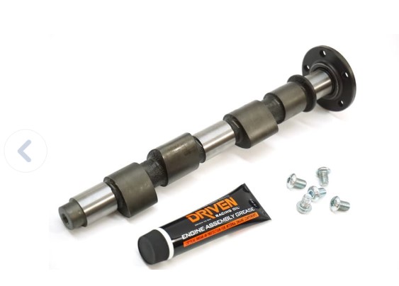 Here is the camshaft of a typical 914, your lobes may vary. So now Krusty Explores the simpler method This then gives rise to a simplified adjustment procedure, which I have printed up and glued into my Haynes manual to replace the rather cumbersome procedure in the book. Removed settings and jack stand advice. **Snip** It follows logically that a valve opposite one that is open is on the back of the same cam lobe, the perfect place for adjustment. It is only necessary to be certain of which valves actually share the same cam lobe, which can be a little tricky owing to the offset nature of the cylinder layout. However, I believe that I have done this and that further, I have worked it out so that, if the valves are adjusted in the order given in the table, a minimum amount of engine rotation will be necessary to complete the task. What he is saying is Exhaust for Cylinder 1&3 uses the lobe circled. 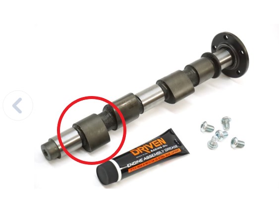 And, the intake for Cylinder 2&4 uses the following lobe that is circled. 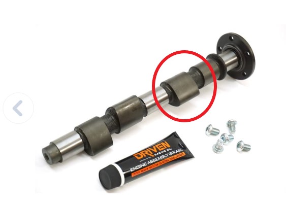 Now- focus on the intake valves for Cylinder 2&4. When the valve in Cylinder 2 is being opened by the lobe it MUST be closed on Cylinder 4. So you can adjust the intake valve on Cylinder 4. VERY CLEAR? Back to the post, when I read his post originally I got lost in this part: It is necessary to use the table of valves that I include; note that in NO case are the two valves that are rocking at the same time associated with the same cylinder. Turn until Rocking: Adjust: #2 Ex & #3 In #4 Ex & #1 In #1 Ex & #2 In #3 Ex & #4 In #4 Ex & #1 In #2 Ex & #3 In #3 Ex & #4 In #1 Ex & #2 In The chart is the same as the text above it. NOW THIS IS WHERE IT GOT VERY CONFUSING FOR ME. The original explanation promises that this is a method that one person could perform. However, in the chart, I was mystified as to why I have to look for 2 valves rocking on opposite sides of the car?????? Example: 2 AND 3, etc. I imagined (prior to thinking about this) that there was a position where #2 Ex and #3 In may not be in sync. This is not the case. THEY CAN NEVER BE OUT OF SYNC since the lobes are 180Deg out of phase. This is where the Sun rose above my marble head. The logic in the chart is wrong! This is the correct Logic: Turn until Rocking: Adjust: #2 Ex OR #3 In #4 Ex & #1 In #1 Ex OR #2 In #3 Ex & #4 In #4 Ex OR #1 In #2 Ex & #3 In #3 Ex OR #4 In #1 Ex & #2 In There is no case where #2 Ex is rocking and #4 Ex & #1 In are NOT Seated. Now this begins to make sense, I could do this from one side of the car for 6 of the 8 valves and then need to move to the other side for 2 of the 8 valves Please make suggestions, I will take the suggestions and then post a cleaner version with better charts, etc. |
| VaccaRabite |
 Mar 12 2020, 11:19 AM Mar 12 2020, 11:19 AM
Post
#40
|
|
En Garde!           Group: Admin Posts: 13,723 Joined: 15-December 03 From: Dallastown, PA Member No.: 1,435 Region Association: MidAtlantic Region 
|
The original explanation promises that this is a method that one person could perform. However, in the chart I was mystified as to why I have to look for 2 valves rocking on opposite sides of the car?????? Example: 2 AND 3, etc. I imagined (prior to thinking about this) that there was a position where #2 Ex and #3 In may not be in sync. This is not the case. THEY CAN NEVER BE OUT OF SYNC since the lobes are 180Deg out of phase. This is where the Sun rose above my marble head. The logic in the chart is wrong! This is the correct Logic: Turn until Rocking: Adjust: #2 Ex OR #3 In #4 Ex & #1 In #1 Ex OR #2 In #3 Ex & #4 In #4 Ex OR #1 In #2 Ex & #3 In #3 Ex OR #4 In #1 Ex & #2 In There is no case where #2 Ex is rocking and #4 Ex & #1 In are NOT Seated. I see where you have gone with this. But. By the same token when 2EX is rocking 3IN is also rocking. And, you want to be SURE they are rocking before you adjust the opposing valves. It only takes a second to swing your head over and make sure. Zach |
  |
1 User(s) are reading this topic (1 Guests and 0 Anonymous Users)
0 Members:

|
Lo-Fi Version | Time is now: 29th April 2025 - 06:56 PM |
Invision Power Board
v9.1.4 © 2025 IPS, Inc.


