|
|

|
Porsche, and the Porsche crest are registered trademarks of Dr. Ing. h.c. F. Porsche AG.
This site is not affiliated with Porsche in any way. Its only purpose is to provide an online forum for car enthusiasts. All other trademarks are property of their respective owners. |
|
|
  |
| Superhawk996 |
 Jul 26 2020, 08:39 AM Jul 26 2020, 08:39 AM
Post
#341
|
|
914 Guru      Group: Members Posts: 7,656 Joined: 25-August 18 From: Woods of N. Idaho Member No.: 22,428 Region Association: Galt's Gulch 
|
So back to some real work.
I had to pull the shifter bushing support off the old sheetmeal and get the pass-thru hole positioned properly. 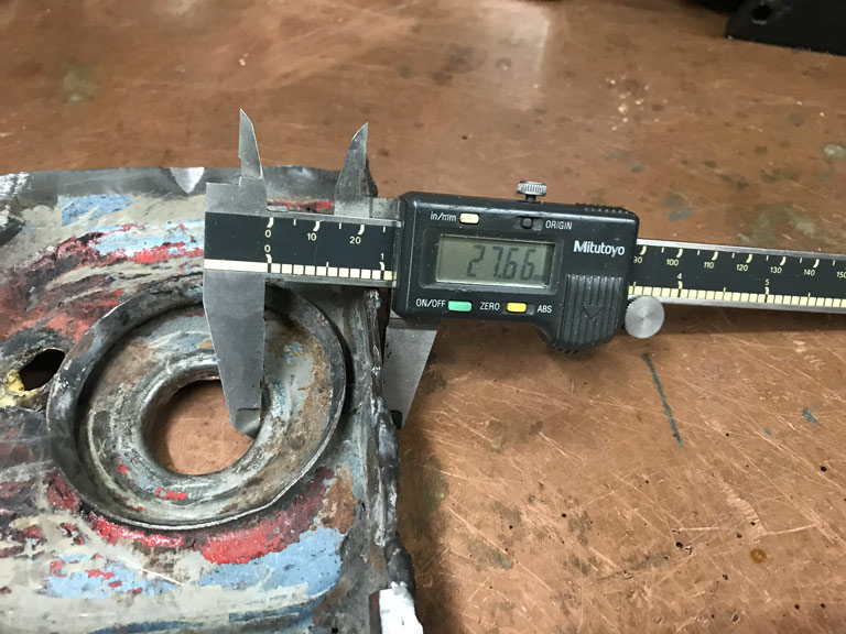 Welded it to the new sheetmetal and got it painted with some Eastwood frame coating to prevent surface rusting until I can get 2K epoxy on the exterior. 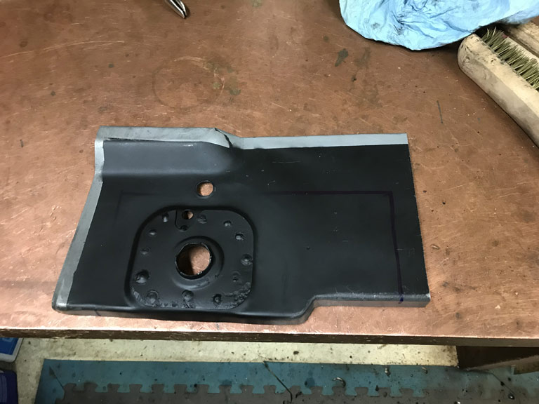 An then spent a couple more quality hours in the engine compartment fitting it up and trimming for welding today. 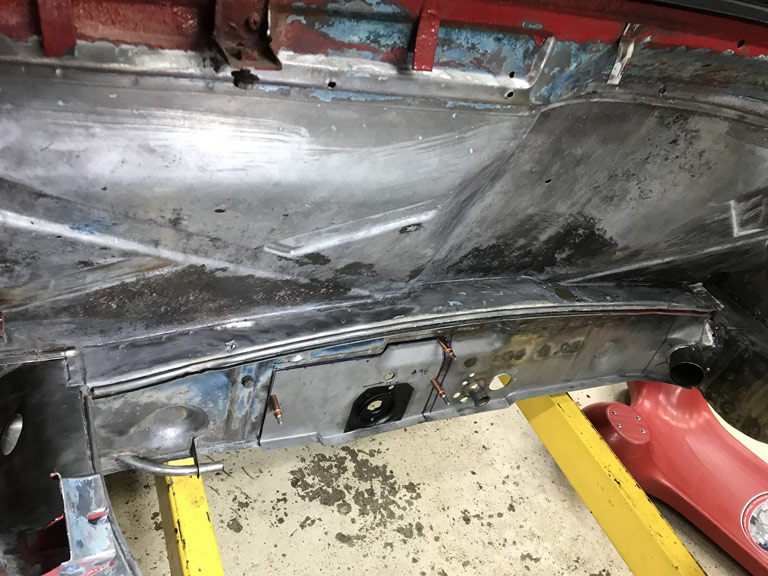 I don't know what it is about working in the "hell hole" but it seems like everytime I get scooted under the car I realize I've forgotten some tool, my sribe, sharpie or whatever. (IMG:style_emoticons/default/hissyfit.gif) |
| Superhawk996 |
 Jul 26 2020, 05:17 PM Jul 26 2020, 05:17 PM
Post
#342
|
|
914 Guru      Group: Members Posts: 7,656 Joined: 25-August 18 From: Woods of N. Idaho Member No.: 22,428 Region Association: Galt's Gulch 
|
(IMG:style_emoticons/default/piratenanner.gif)
Outer bulkhead panel is done. I have the leftover piece of the panel outboard of the shifter left and won't be using it. If anyone is needs it, it's yours for the cost of shipping. Seems to take forever to get even these little panels installed. (IMG:style_emoticons/default/dry.gif) 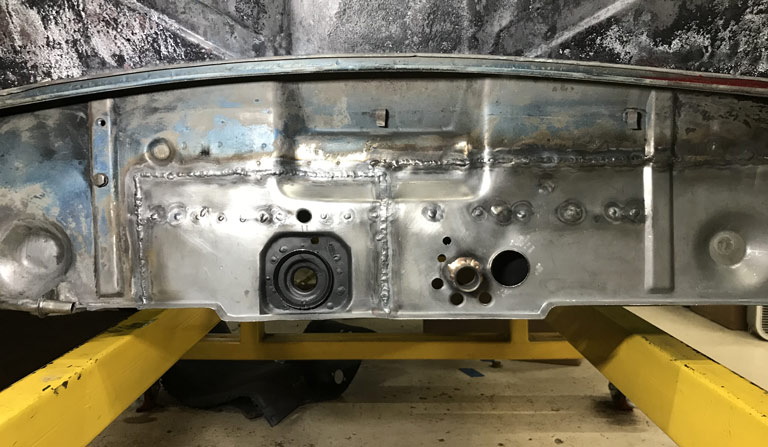 Really pleased with the weld penetration. 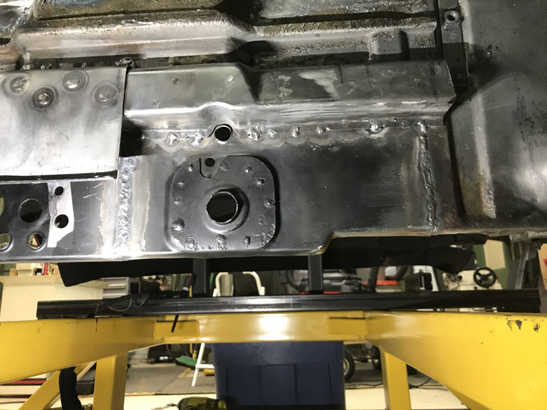 Nice and strong and will clean up with minimal weld clean up from the front side when it's time to do the finish work. 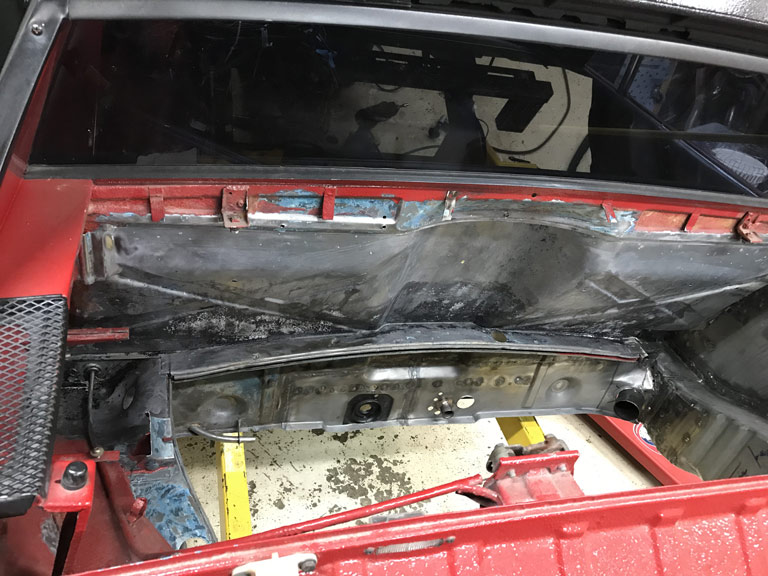 Looks like I can spend some time after work this week getting the inner panel ready for install. |
| BeatNavy |
 Jul 26 2020, 05:48 PM Jul 26 2020, 05:48 PM
Post
#343
|
|
Certified Professional Scapegoat     Group: Members Posts: 2,960 Joined: 26-February 14 From: Easton, MD Member No.: 17,042 Region Association: MidAtlantic Region 
|
That looks really clean and well done. Nice job. That lower firewall is NOT easy!
|
| Superhawk996 |
 Aug 2 2020, 10:45 AM Aug 2 2020, 10:45 AM
Post
#344
|
|
914 Guru      Group: Members Posts: 7,656 Joined: 25-August 18 From: Woods of N. Idaho Member No.: 22,428 Region Association: Galt's Gulch 
|
Thought I'd be welding in the last portion of the driver side inner bukhead panel but it turns out that I've got two headaches.
One is real and I don't feel like welding right now. Probably dehydrated and need to drink more water and a couple Ibuprofen will help. Hopefully I'll be fixed shortly and welding in an hour or so. The other headache was the repair panel I purchased from RD is missing a form feature to clear the floorpan stiffening dart. I'm mildly disappointed in RD. I really like these guys! But, the 325L panel that I purchased from them needed way more fabrication work than the similar part on the passenger side that I purased from AA for only about $10 more. As I was finishing up panel prep yesterday, I noticed the lack of the floorpan form feature. Initially I was thinking maybe that floor pan stiffening dart isn't on the driver side. Quick mockup of the floorpan has a dart there. 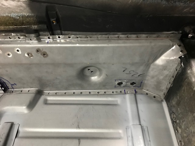 (IMG:style_emoticons/default/stromberg.gif) More work to prep the panel needed before I can weld it in. In addition to this form feature, I also had to completely do the weld flange inside the tunnel. Yeah, Yeah . . . I know all panels are going to need some tweaking. But the AA panel on the passenger side had the tunnel flange formed by the stamping dies and fit the tunnel near perfectly as received. All in all, this was a couple additional hours of panel prep that I didn't have to do on the AA panel used for the passenger side. 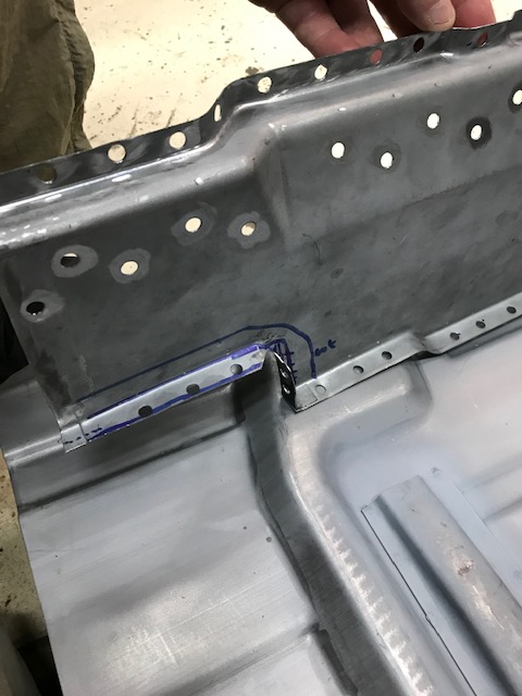 Don't get me wrong. I'd still go to RD for panels but was just surprised and/or disappointed that I had to do this work on the RD driver side part and not on the AA passenger side part. Likewise, I can't say with certaintly that the AA driver side part is any better. Just posting as information but not trying to run down RD. Anyway, it as a good chance to get the floor pan halves and the donor tunnel in for a quick mockup. Nowhere near ready to weld in floorpan yet but sometimes just seeing a mockup give me a sense of hope & progress. 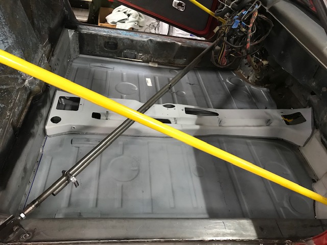 11/10/2020 update: have heard from @peteyd at RD that the 325L panel stamping has been revised to add the floor pan formation to more easily fit up. Great company, great customer service on all that I’ve ordered and most importantly incorporating continuous improvement to make their products even better! |
| Superhawk996 |
 Aug 3 2020, 02:39 AM Aug 3 2020, 02:39 AM
Post
#345
|
|
914 Guru      Group: Members Posts: 7,656 Joined: 25-August 18 From: Woods of N. Idaho Member No.: 22,428 Region Association: Galt's Gulch 
|
(IMG:style_emoticons/default/mad.gif) Got up at 4:30am meeting with Asia only to find out they cancelled the meeting about an hour ago after I had already gone to bed (IMG:style_emoticons/default/chair.gif)
Driver side lower bulkhead sucessfully installed last night. 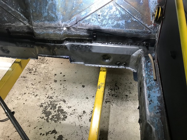 Time to move on to another section of bad sheetmetal and the last before I can install floorpan. Next up: The driver pedal box area and driver side wheelhouse. |
| Superhawk996 |
 Aug 3 2020, 08:03 AM Aug 3 2020, 08:03 AM
Post
#346
|
|
914 Guru      Group: Members Posts: 7,656 Joined: 25-August 18 From: Woods of N. Idaho Member No.: 22,428 Region Association: Galt's Gulch 
|
This jalopy supposedly was a Florida car. I did find some sand in the passenger side longitudinal when I cut that apart which was completely replaced. Video below is of the driver side.
https://www.youtube.com/watch?v=PXeAENauvsY Looks like I'll be at least doing a small trap door in the driver side longitudinal to get the rest of the sand out. There were small rust holes in the rear portion of the front wheel wheel to longitudinal area - I'm pretty sure this is how the sand got in there. Will also need to run a borescope into driver side long just to make sure. Everything is solid with a pick and no signs of pinholes but better safe than sorry. |
| tygaboy |
 Aug 3 2020, 08:07 AM Aug 3 2020, 08:07 AM
Post
#347
|
|
914 Guru      Group: Members Posts: 5,754 Joined: 6-October 15 From: Petaluma, CA Member No.: 19,241 Region Association: Northern California 
|
It's fascinating to me how we each approach the repair process. I've done two cars worth of that lower firewall/rear floor repair and it wouldn't have occurred to me to install the firewall before the floor.
Not challenging your approach at all, just fun to see the other ways folks do things. Regardless, you're moving right along and it's looking great! (IMG:style_emoticons/default/aktion035.gif) |
| Superhawk996 |
 Aug 3 2020, 08:14 AM Aug 3 2020, 08:14 AM
Post
#348
|
|
914 Guru      Group: Members Posts: 7,656 Joined: 25-August 18 From: Woods of N. Idaho Member No.: 22,428 Region Association: Galt's Gulch 
|
It's fascinating to me how we each approach the repair process. I've done two cars worth of that lower firewall/rear floor repair and it wouldn't have occurred to me to install the firewall before the floor. Not challenging your approach at all, just fun to see the other ways folks do things. Regardless, you're moving right along and it's looking great! (IMG:style_emoticons/default/aktion035.gif) @tygaboy Considering my aproach was to build the passenger side innner wheel well and long from the inside out to avoid cutting the rear fender it's no wonder I'm doing it backwards. (IMG:style_emoticons/default/av-943.gif) Plus, I need the floorpan out to better access the driver footbox and wheelhouse area. Had I been able to save the tunnel and/or more of the lower 1" perimeter, I would have done it differently. My thought was that the floorpan doesn't offer any vertical stiffness or vertical structure which would move around my suspension points in Z height. The floor pan does prevent matchboxing fore/aft movement though and I've tried to brace this movement with the diagonal brace. The potential for movement keeps me measuring my suspension pickup points like an OCD maniac though. |
| Superhawk996 |
 Aug 9 2020, 08:33 AM Aug 9 2020, 08:33 AM
Post
#349
|
|
914 Guru      Group: Members Posts: 7,656 Joined: 25-August 18 From: Woods of N. Idaho Member No.: 22,428 Region Association: Galt's Gulch 
|
Well in an effort to get all the sand out of the driver longitudinal, I had to cut some holes.
The front driver side longitudinal had some minor rust at the transition to the floorpan. This was an obvious place to put an access hole. It won't be seen once reapaird and the floopan is reinstalled. 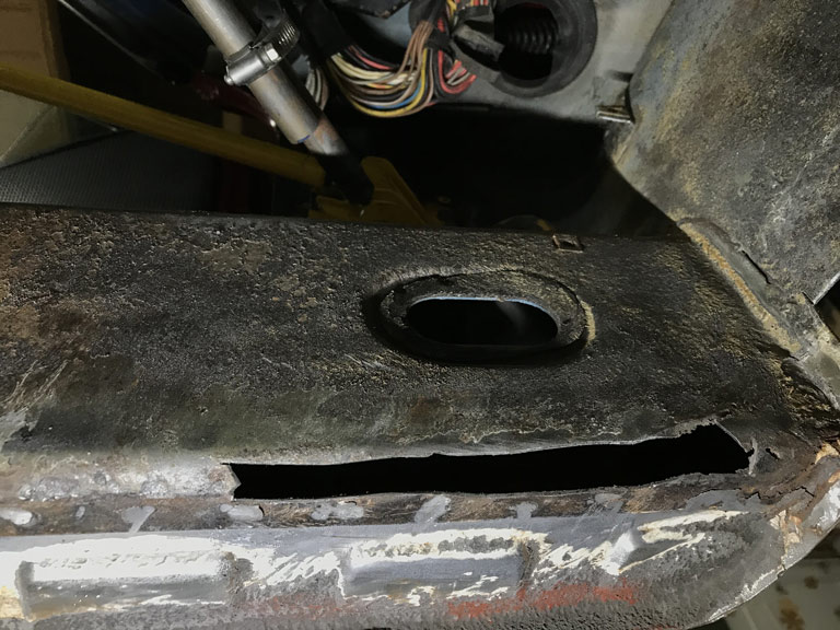 The rear was obvious too. There was a poor repair of the driver side jack point and I wanted to see what was under there. Usually it is rusted out in this area from the pyramid holding water and debris leading to localized rot. Sure enough. 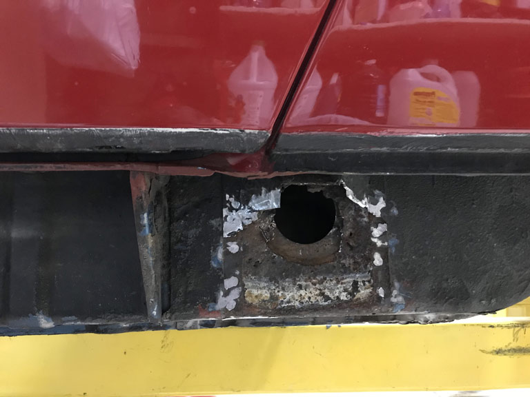 Having removed the sand over the course of several hours of swearing and cutting up my hands manipulating a small section of 3/8" vinyl hose (attached to shop vac) back and forth in the long though these access holes, I moved on. Demolition of the pedal box area was entertaining. The floor pan that normally covers the rear mounting point for the front cross member was basically gone. Simply covered with a skim of fiberglass, rotted sheetmetal, and of course undercoating to hide the whole (IMG:style_emoticons/default/stromberg.gif) show. 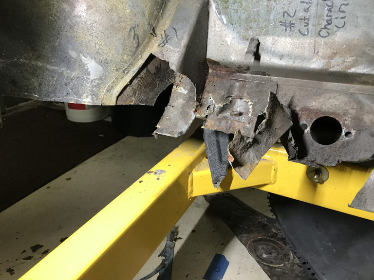 Well at least I'm moving forward and no longer working in the engine compartment for a while. We'll see about that because I might be cutting a surgical flap via the driver side wheel house inner in order to properly repair that driver side jack point. We'll see. |
| Superhawk996 |
 Aug 9 2020, 08:50 AM Aug 9 2020, 08:50 AM
Post
#350
|
|
914 Guru      Group: Members Posts: 7,656 Joined: 25-August 18 From: Woods of N. Idaho Member No.: 22,428 Region Association: Galt's Gulch 
|
The aftermarket bearing vs. Porsche OEM bearing saga continues.
I ordered two half shells at about $45 each that serve as main bearings for bearings #2 through #7. I was hoping that they would measure a little tighter than aftermarket Glyco as bearing #1 half shells did. 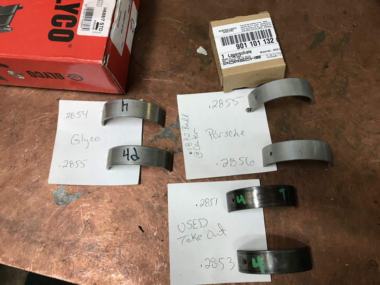 Nope. Well, maybe by 0.0001" - 0.0002" but I was hoping for something significant. (IMG:style_emoticons/default/wacko.gif) |
| 914forme |
 Aug 9 2020, 10:22 AM Aug 9 2020, 10:22 AM
Post
#351
|
|
Times a wastin', get wrenchin'!     Group: Members Posts: 3,899 Joined: 24-July 04 From: Dayton, Ohio Member No.: 2,388 Region Association: None 
|
What is the goal?
From what I see you have had .0004 and .0003 wear on the bearing surfaces. What are your crank journals. General rule of thumb is your looking for crank bearing clearance of 0.0020 - 0.0025. I know you most likely know this, and or have access to the people who do know being part of th automotive industry. But with out the magical numbers and what these are once in the saddle and cap. We are just guessing with the clues given. Unless it was detailed a while ago and I did not read it. (IMG:style_emoticons/default/confused24.gif) |
| bkrantz |
 Aug 9 2020, 08:43 PM Aug 9 2020, 08:43 PM
Post
#352
|
|
914 Guru      Group: Members Posts: 8,590 Joined: 3-August 19 From: SW Colorado Member No.: 23,343 Region Association: Rocky Mountains 
|
Demolition of the pedal box area was entertaining. The floor pan that normally covers the rear mounting point for the front cross member was basically gone. Simply covered with a skim of fiberglass, rotted sheetmetal, and of course undercoating to hide the whole (IMG:style_emoticons/default/stromberg.gif) show.  Well at least I'm moving forward and no longer working in the engine compartment for a while. We'll see about that because I might be cutting a surgical flap via the driver side wheel house inner in order to properly repair that driver side jack point. We'll see. With all the crimes committed with undercoating, maybe it should be locked up and sold only to those with good intentions (and skills). |
| Superhawk996 |
 Aug 10 2020, 03:52 AM Aug 10 2020, 03:52 AM
Post
#353
|
|
914 Guru      Group: Members Posts: 7,656 Joined: 25-August 18 From: Woods of N. Idaho Member No.: 22,428 Region Association: Galt's Gulch 
|
What is the goal? From what I see you have had .0004 and .0003 wear on the bearing surfaces. What are your crank journals. General rule of thumb is your looking for crank bearing clearance of 0.0020 - 0.0025. I know you most likely know this, and or have access to the people who do know being part of th automotive industry. But with out the magical numbers and what these are once in the saddle and cap. We are just guessing with the clues given. Unless it was detailed a while ago and I did not read it. (IMG:style_emoticons/default/confused24.gif) @914forme Agree with Goal of 0.0025 - 0.0003". The issue I had was that Line bore is at the high end of spec and the crank is about 0.0005" above wear limit and main bearing clearance was coming in at about 0.004" +/- a few tenhs, measued with bore gage and seemed to have a lack of complete crush on 0.003" Platigauge. I'll probably do another trial assembly with crank nose bearing in place to double check all this. But it's looking more like crank is going to have to go undersize to get to 0.0025". Of course that also means undersize main bearings. This is why I was trying to figure out if there was something to be gained with the super expensive OEM bearings from Porsche. Will likely do a triple check with the next size up of Plastigauge too that cover 0.004" and larger. |
| 914forme |
 Aug 10 2020, 05:05 AM Aug 10 2020, 05:05 AM
Post
#354
|
|
Times a wastin', get wrenchin'!     Group: Members Posts: 3,899 Joined: 24-July 04 From: Dayton, Ohio Member No.: 2,388 Region Association: None 
|
Got it, best of luck
|
| Superhawk996 |
 Aug 15 2020, 12:36 PM Aug 15 2020, 12:36 PM
Post
#355
|
|
914 Guru      Group: Members Posts: 7,656 Joined: 25-August 18 From: Woods of N. Idaho Member No.: 22,428 Region Association: Galt's Gulch 
|
Well the time has come to do the part I've been dreading for a while. Time to fix the pedal box area.
Part of the dread was over stripping of the seam sealer from the area under the gas tank. My Wurth flail wheel won't fit in there. Turns out it wasn't so hard to do with a drill and really stiff wire wheel. Access sucks but it was doable. 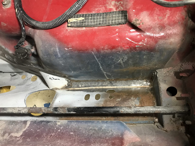 Next up was the need to create a tuna can flap to gain access to the area. The weld seam will go right below the area where the flap is normally spot welded down. This will give me a nice area to weld to with double metal thickness. 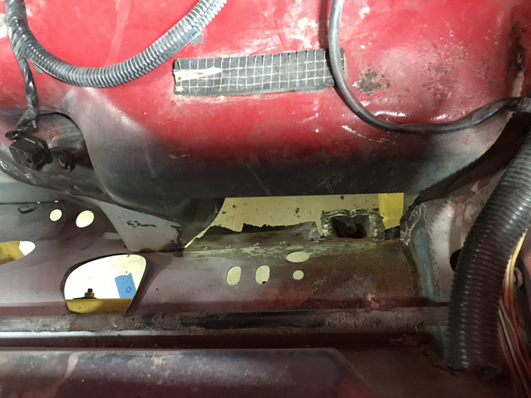 And as viewed inside the cabin. 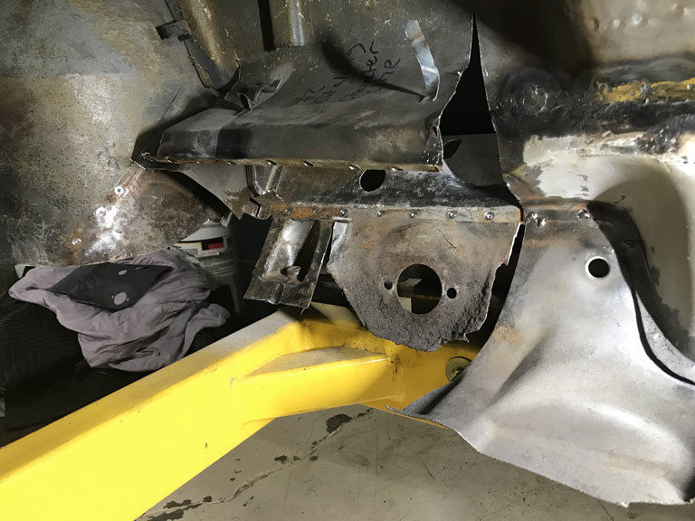 Currently prepping the new sheet metal with POR15 Metal Prep as I add this build entry. I've tried both Ospho and POR15 Metal Prep and I'm leaning toward the Metal Prep as my preferred product. Just seems to work better for me and leaves a thin layer of zinc that holds off the surface rust until I can get primer on it. |
| Superhawk996 |
 Aug 16 2020, 04:08 PM Aug 16 2020, 04:08 PM
Post
#356
|
|
914 Guru      Group: Members Posts: 7,656 Joined: 25-August 18 From: Woods of N. Idaho Member No.: 22,428 Region Association: Galt's Gulch 
|
Well I knew this was going to be a PITA and it's turning out to be that way. (IMG:style_emoticons/default/hissyfit.gif)
Initially I was hoping to use the donor sheet metal as-is without having to remove the suspension point that anchors the steering crossmember at the front firewall area. There was simply too much car to car variation to make it work. I had initially marked the cross car postion of the pedal sled & master cylinder mount as reference. There was no way to get that dimension to where it started and to simultaneously have the downward turned flange of the wheelhouse in the right place. So off with the old pick up point. I have a new one from RD anyway just in case. I guess that was a good call. (IMG:style_emoticons/default/happy11.gif) 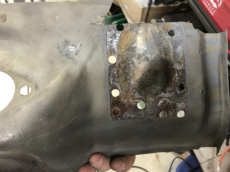 The positive side is that I can now sandblast the corrosion that was trapped internally. (IMG:style_emoticons/default/smile.gif) Next problem was to make sure the floorpan character lines lined up between left side and the right side AND to have the pedal sled fit. More mockup. 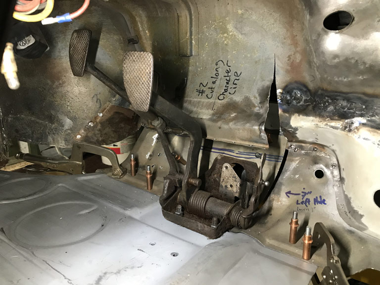 Well, when all is said and done, with everything where it belongs, I have about a 6-7mm gap between the panels. (IMG:style_emoticons/default/headbang.gif) Not insurmountable but it goes to show how much variability there can be beween donor sheetmetal and the vehicle it's going into. I would have expected a 3mm gap simply from the (IMG:style_emoticons/default/sawzall-smiley.gif) kerf when I split the panel over a year ago. The other 3mm is basically car to car variation. It will all work out after I trim a thin gap filler and I'll be sure to use a copper backer to prevent welding problems. . . . I hope. (IMG:style_emoticons/default/rolleyes.gif) 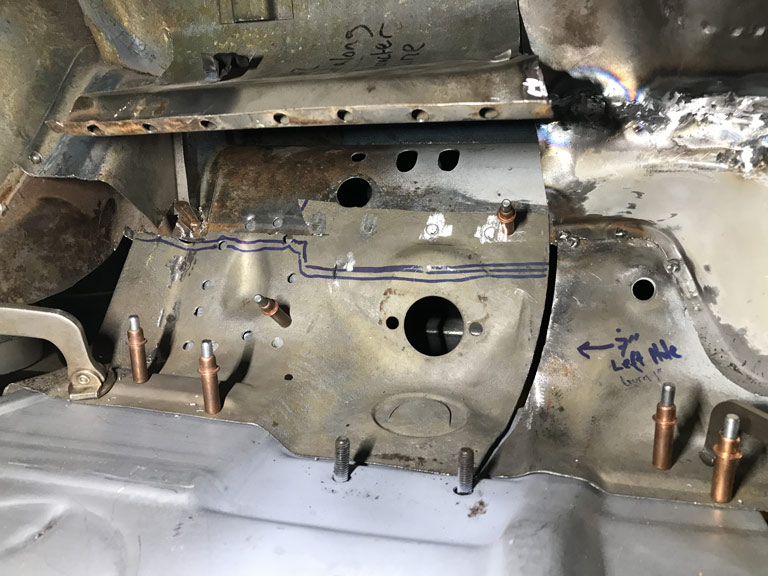 |
| Superhawk996 |
 Aug 19 2020, 05:25 AM Aug 19 2020, 05:25 AM
Post
#357
|
|
914 Guru      Group: Members Posts: 7,656 Joined: 25-August 18 From: Woods of N. Idaho Member No.: 22,428 Region Association: Galt's Gulch 
|
Weeknight project was to get three tachometers bench tested to verify functionality.
Quick overview of setup details in the video. Currently working to setup as a little Arduino program that can do this without all the test equipment. This was done manually with a frequency generator controlling the frequency of the pulses to make sure the setup with a MOSFET driver was going to work to drive the coil. https://www.youtube.com/watch?v=EO3XCJQ9tW4 |
| bbrock |
 Aug 19 2020, 08:07 AM Aug 19 2020, 08:07 AM
Post
#358
|
|
914 Guru      Group: Members Posts: 5,269 Joined: 17-February 17 From: Montana Member No.: 20,845 Region Association: Rocky Mountains 
|
That's awesome! If you get the Arduino setup working, I may have to copy it. Nice work on that pedal box too. (IMG:style_emoticons/default/beerchug.gif)
|
| Root_Werks |
 Aug 19 2020, 08:53 AM Aug 19 2020, 08:53 AM
Post
#359
|
|
Village Idiot      Group: Members Posts: 8,884 Joined: 25-May 04 From: About 5NM from Canada Member No.: 2,105 Region Association: Pacific Northwest 
|
I haven't been keeping up on this thread enough, wow! It's come a long way, keep at it!
|
| bkrantz |
 Aug 19 2020, 09:13 PM Aug 19 2020, 09:13 PM
Post
#360
|
|
914 Guru      Group: Members Posts: 8,590 Joined: 3-August 19 From: SW Colorado Member No.: 23,343 Region Association: Rocky Mountains 
|
Nice work on the pedal box area. That's one I did not have to repair on mine, and glad to skip it.
|
  |
1 User(s) are reading this topic (1 Guests and 0 Anonymous Users)
0 Members:

|
Lo-Fi Version | Time is now: 4th February 2026 - 01:16 AM |
Invision Power Board
v9.1.4 © 2026 IPS, Inc.


