|
|

|
Porsche, and the Porsche crest are registered trademarks of Dr. Ing. h.c. F. Porsche AG.
This site is not affiliated with Porsche in any way. Its only purpose is to provide an online forum for car enthusiasts. All other trademarks are property of their respective owners. |
|
|
  |
| doug_b_928 |
 May 23 2019, 08:51 PM May 23 2019, 08:51 PM
Post
#21
|
|
Senior Member    Group: Members Posts: 712 Joined: 17-January 13 From: Winnipeg Member No.: 15,382 Region Association: Canada |
I finally got my engine run stand completed. It took a lot more work than I had thought it would. This stand is very specific to my needs, but I thought I'd share in case it gives anyone else some ideas for their own stand. I made the distance between the castors at 45" so that I can load and unload it from my trailer without moving the ramps. It also sports a hitch for attaching my winch and tie down points on all four corners.
Here it is in the 'installation position', meaning the bars that hold the relay board on the left side and the MPS and decel valve on the right side are folded down. 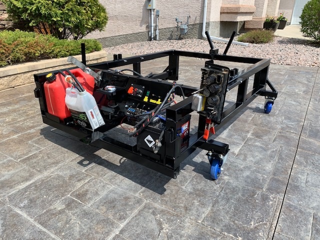 I have a max jax, so I simply roll the stand under the car 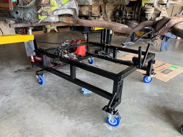 I made the back side open so that I can roll my lift table under the stand 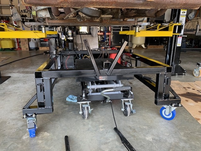 Then I raise the lift table to support the engine and unbolt the engine from the car. 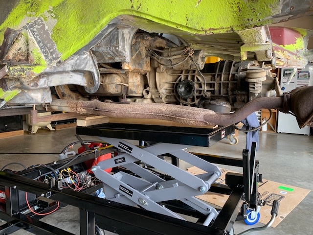 Then I lower the engine onto the stand 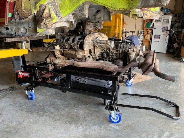 I also made a bar that I can install from underneath. It supports both the engine and the transmission. In theory, I can then separate the trans from the engine and have both still supported (makes it easier for doing this work alone). 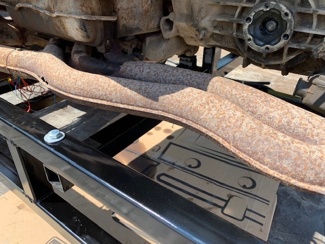 Here is the stand with the attachments in the 'run' position. 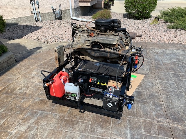 I made a throttle lever that I can tighten in position with a wing nut, so that I can hold rpms over 2000 for cam break in. Here's a pic of the control panel. 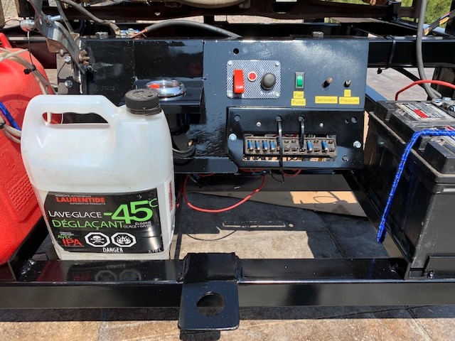 Many thanks again to Spoke for his help with the wiring. Everything works as expected. |
| bbrock |
 May 23 2019, 08:56 PM May 23 2019, 08:56 PM
Post
#22
|
|
914 Guru      Group: Members Posts: 5,269 Joined: 17-February 17 From: Montana Member No.: 20,845 Region Association: Rocky Mountains 
|
Wow Doug! That is the mother of all run stands. Nice work (IMG:style_emoticons/default/thumb3d.gif)
|
| Superhawk996 |
 May 24 2019, 03:44 AM May 24 2019, 03:44 AM
Post
#23
|
|
914 Guru      Group: Members Posts: 6,598 Joined: 25-August 18 From: Woods of N. Idaho Member No.: 22,428 Region Association: Galt's Gulch 
|
(IMG:style_emoticons/default/biggrin.gif) Nice stand. Great job!
I'll likely build something similar to start an engine and just make sure I can get D jet firing and the engine running before I go to the trouble of installing the engine. One point of note. Don't assume the engine stand will provide a complete break in. You want varying load on the engine as well as just varying RPM's without load. You probably know that already but I wanted to put it out there. Stands are a great way to verify basic functionality though! |
| doug_b_928 |
 May 24 2019, 06:17 AM May 24 2019, 06:17 AM
Post
#24
|
|
Senior Member    Group: Members Posts: 712 Joined: 17-January 13 From: Winnipeg Member No.: 15,382 Region Association: Canada |
Thanks guys. I didn’t know that about break-in. So once you have the cam broken-in on the stand and the engine installed in the car, do you just do like the new cars and keep it under 4,000 rpm for x number of miles?
|
| Superhawk996 |
 May 24 2019, 06:50 AM May 24 2019, 06:50 AM
Post
#25
|
|
914 Guru      Group: Members Posts: 6,598 Joined: 25-August 18 From: Woods of N. Idaho Member No.: 22,428 Region Association: Galt's Gulch 
|
Thanks guys. I didn’t know that about break-in. So once you have the cam broken-in on the stand and the engine installed in the car, do you just do like the new cars and keep it under 4,000 rpm for x number of miles? Break in is a debated topic full of myth, legend and handed down stories. (IMG:style_emoticons/default/happy11.gif) I'd suggest reading various opinions from engine builders and deciding for yourself. Tom Wilson How to Rebuild your Volkswagen Air Cooled Engine book is a good starting point. I'll give you a couple of personal opinions: New cars do really don't need break like we typically think of for vintage engines. I say this as an automotive engineer working in the industry. There are a ton of reasons for this ranging from metallurgy to manufacturing methods and modern tolerances. That said, a mild break in is still called for and isn't a bad thing. Bottom line we design cars knowing that most can't or won't take the time to do a break in. We now do extensive dyno testing and thermal shock type testing that wasn't done in the 70's. We do lots of -40F cold starts and rapid drive away testing that would make you cringe and engines still survive. The list goes on. The reason for varying load and RPM's is to get the rings well seated to the cylinder walls and within the piston groves. Varying RPM and load helps expedite this process. I'll spare you the long form explanation of why this is so. Think rod stretch, thermal expansion, and variances in combustion pressures and you'll be on the right track. The best thing during this process is to get it running, let it run under light load with some variance of RPM's and then to dump the oil after say 20 minutes. Get rid of the fine particles of metal that are shedding from everywhere. Then change oil after about 100 miles driving. Then again at 300. And again at 1000 miles. keep the oil clean during this process. Use Dinosaur oil. It will work better for break in and is cheaper too since you'll be using a lot of it. Now let the controversy begin. (IMG:style_emoticons/default/stirthepot.gif) |
| VaccaRabite |
 May 24 2019, 07:08 AM May 24 2019, 07:08 AM
Post
#26
|
|
En Garde!           Group: Admin Posts: 13,616 Joined: 15-December 03 From: Dallastown, PA Member No.: 1,435 Region Association: MidAtlantic Region 
|
The break in that I used is the Raby method from many years ago.
As soon as the engine starts for the first time after a rebuild, run it for 20 minutes at 2K RPM. That is to break in the cam and lifters. Once the engine is in the car, go for a drive to get it warm. Then hammer it in 2nd gear all the way to redline and let it cost back down to a crawl, then hammer it all the way back up to redline and let the car coast back down again. And that is the break in to seat the rings. Zach |
| doug_b_928 |
 May 25 2019, 07:30 AM May 25 2019, 07:30 AM
Post
#27
|
|
Senior Member    Group: Members Posts: 712 Joined: 17-January 13 From: Winnipeg Member No.: 15,382 Region Association: Canada |
Interesting info on break-in, guys. Jake's method certainly sounds like fun!
I have to say it's very satisfying to see it actually work. Here's a link to a short youtube video of the stand 'in action': https://youtu.be/o4QHTLtkIzU |
| Superhawk996 |
 May 25 2019, 07:55 AM May 25 2019, 07:55 AM
Post
#28
|
|
914 Guru      Group: Members Posts: 6,598 Joined: 25-August 18 From: Woods of N. Idaho Member No.: 22,428 Region Association: Galt's Gulch 
|
I was wondering what you were going to do with that stand on that awesome patio as I thought to myself about notorious 914 oil leaks.
Glad to see you employed the standard solution - cardboard box. (IMG:style_emoticons/default/av-943.gif) Improved version = built in oil catch pan. (IMG:style_emoticons/default/laugh.gif) Really nice job -- video is great. (IMG:style_emoticons/default/first.gif) |
| doug_b_928 |
 May 25 2019, 10:52 AM May 25 2019, 10:52 AM
Post
#29
|
|
Senior Member    Group: Members Posts: 712 Joined: 17-January 13 From: Winnipeg Member No.: 15,382 Region Association: Canada |
Well....I admit that some leaked on the concrete before I noticed. It's leaking like a sieve from the right valve cover. Sealing that concrete is one of my many 'yard tasks' that has been delayed due to the time it took to finish this engine stand. On that note, I'm sticking with the cardboard rather than engineering a removable oil catch tray... (IMG:style_emoticons/default/biggrin.gif)
|
| cary |
 Nov 28 2019, 10:31 AM Nov 28 2019, 10:31 AM
Post
#30
|
|
Advanced Member     Group: Members Posts: 3,900 Joined: 26-January 04 From: Sherwood Oregon Member No.: 1,608 Region Association: Pacific Northwest 
|
Thanks doug b 928, Jack and I are about ready to start wiring our test stand.
|
| doug_b_928 |
 Nov 28 2019, 10:40 AM Nov 28 2019, 10:40 AM
Post
#31
|
|
Senior Member    Group: Members Posts: 712 Joined: 17-January 13 From: Winnipeg Member No.: 15,382 Region Association: Canada |
Post up some pics/link to vid when you get it done. (IMG:style_emoticons/default/beerchug.gif)
|
| cary |
 Nov 28 2019, 10:43 AM Nov 28 2019, 10:43 AM
Post
#32
|
|
Advanced Member     Group: Members Posts: 3,900 Joined: 26-January 04 From: Sherwood Oregon Member No.: 1,608 Region Association: Pacific Northwest 
|
D Jet was just plug and play coming out of the relay board ?
|
| doug_b_928 |
 Nov 28 2019, 10:46 AM Nov 28 2019, 10:46 AM
Post
#33
|
|
Senior Member    Group: Members Posts: 712 Joined: 17-January 13 From: Winnipeg Member No.: 15,382 Region Association: Canada |
I'm not sure exactly what you're asking. Everything from the relay board to the engine is as it is in the car. Everything from the relay board to the control panel I made myself from scrap pieces from an old harness.
|
| cary |
 Nov 28 2019, 11:13 AM Nov 28 2019, 11:13 AM
Post
#34
|
|
Advanced Member     Group: Members Posts: 3,900 Joined: 26-January 04 From: Sherwood Oregon Member No.: 1,608 Region Association: Pacific Northwest 
|
That was the question. As it is.
Didn't see anything in your schematic, but thought I should ask. Thanks. |
| cary |
 Dec 21 2019, 01:19 PM Dec 21 2019, 01:19 PM
Post
#35
|
|
Advanced Member     Group: Members Posts: 3,900 Joined: 26-January 04 From: Sherwood Oregon Member No.: 1,608 Region Association: Pacific Northwest 
|
Here's a couple shots of our progress. Engine drop stand is detachable. Car drops right onto to stand. Run portion is a separate cart. Arms will turn 90 degrees and out of the way when not in use.
Can't thank you enough for the wiring diagram. 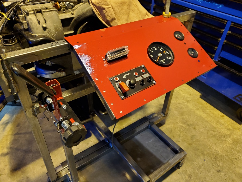 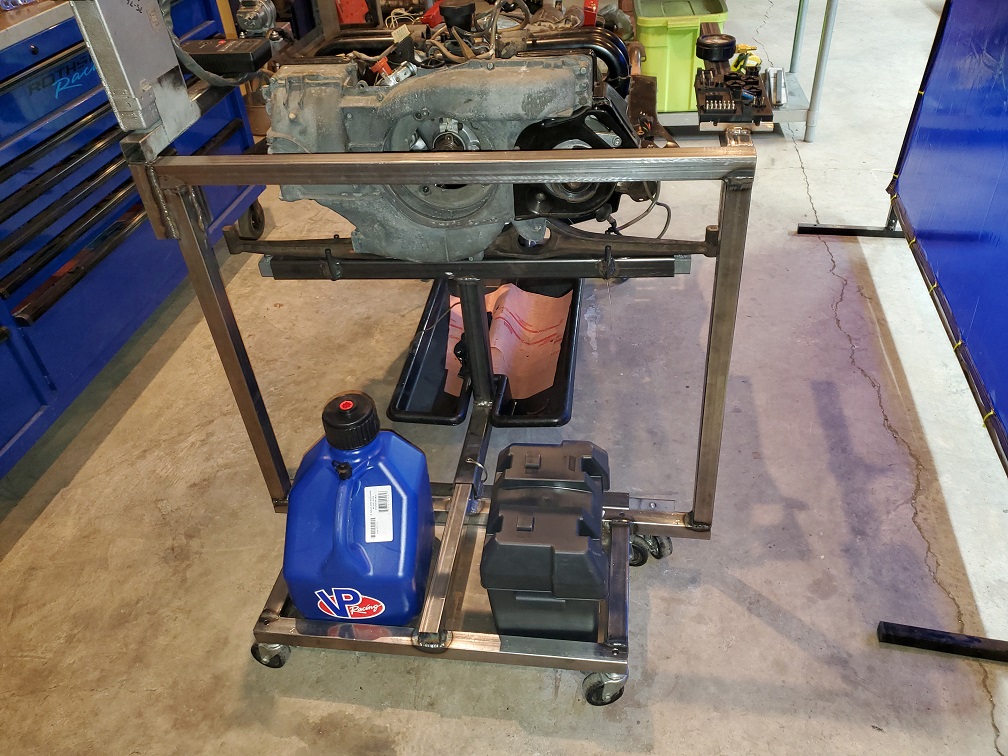 |
| doug_b_928 |
 Dec 22 2019, 07:54 AM Dec 22 2019, 07:54 AM
Post
#36
|
|
Senior Member    Group: Members Posts: 712 Joined: 17-January 13 From: Winnipeg Member No.: 15,382 Region Association: Canada |
Looks really nice Cary!
|
| BeatNavy |
 Dec 22 2019, 08:10 AM Dec 22 2019, 08:10 AM
Post
#37
|
|
Certified Professional Scapegoat     Group: Members Posts: 2,944 Joined: 26-February 14 From: Easton, MD Member No.: 17,042 Region Association: MidAtlantic Region 
|
That is a super sweet setup, Cary. Wouldn't expect anything less from you, though (IMG:style_emoticons/default/smile.gif)
|
| Spoke |
 Dec 22 2019, 09:28 AM Dec 22 2019, 09:28 AM
Post
#38
|
|
Jerry      Group: Members Posts: 7,104 Joined: 29-October 04 From: Allentown, PA Member No.: 3,031 Region Association: None 
|
Nice looking stands. One thing I noticed about the schematic I showed before, the alternator was not part of the schematic. Here is an updated schematic with the alternator shown connected directly to the battery as in the car.
The 3 wire cable from the alternator to the VR on the relay board is not shown as that is a direct connection and not something that needs to be detailed on this schematic. Attached thumbnail(s) 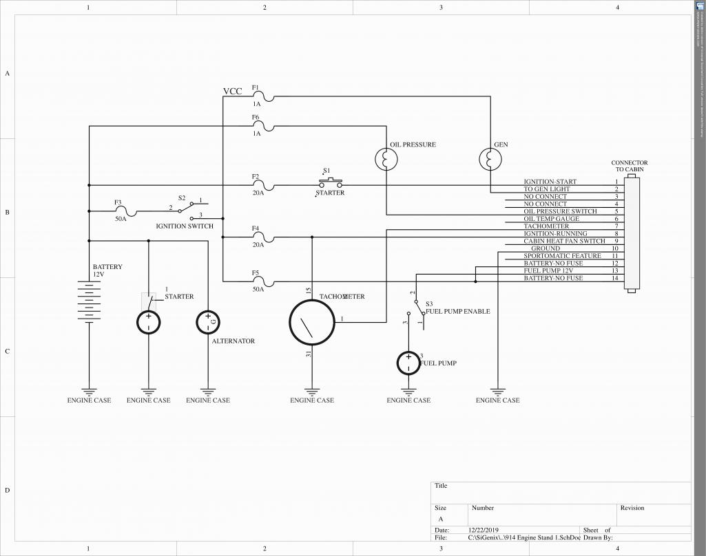
|
| cary |
 Dec 30 2019, 11:12 AM Dec 30 2019, 11:12 AM
Post
#39
|
|
Advanced Member     Group: Members Posts: 3,900 Joined: 26-January 04 From: Sherwood Oregon Member No.: 1,608 Region Association: Pacific Northwest 
|
Spoke ???
I ran separate fused wires to 12 & 14 on the relay board. What size fuse ? I see you call out 50amp on on the double wire. |
| cary |
 Jan 2 2020, 09:46 AM Jan 2 2020, 09:46 AM
Post
#40
|
|
Advanced Member     Group: Members Posts: 3,900 Joined: 26-January 04 From: Sherwood Oregon Member No.: 1,608 Region Association: Pacific Northwest 
|
After sitting 8 years assembled the DP engine finally running on the engine stand.
Can't help you with the muffler sound .............. Might buy a new Bursch for my car and let DP hear the difference. https://www.youtube.com/watch?v=SJ03kmJpZfE https://www.youtube.com/watch?v=jb55tGh-Cpg Wish I could tinker some more, but she'll sit till the chassis is repaired. I'll take some shots of the control unit when I pull it off today. |
  |
2 User(s) are reading this topic (2 Guests and 0 Anonymous Users)
0 Members:

|
Lo-Fi Version | Time is now: 26th December 2024 - 10:22 PM |
Invision Power Board
v9.1.4 © 2024 IPS, Inc.


