|
|
|
Porsche, and the Porsche crest are registered trademarks of Dr. Ing. h.c. F. Porsche AG.
This site is not affiliated with Porsche in any way. Its only purpose is to provide an online forum for car enthusiasts. All other trademarks are property of their respective owners. |
|
|

  |

| Morrie |
 Jul 26 2019, 12:05 PM Jul 26 2019, 12:05 PM
Post
#21
|
|
Member  Group: Members Posts: 181 Joined: 8-October 07 From: Cedar Park, Texas Member No.: 8,198 Region Association: Southwest Region |
QUOTE(JeffBowlsby @ Jul 25 2019, 10:45 PM)  Black/Red on the IGNITION harness goes to the coil. As does the Black/Purple. White wire with a box connector goes to the AAR. Wire on the AAR is red. Thank you Jeff for the advice, and for your patience while I try and sort this all out. I am out of town but I did find a picture I took before starting to sort all the wiring. You can see the black/red wire that is connected to what I believe is the thermotime switch. On the right side of the picture you see a tattered white wire (I will address that) attached to the AAR wire. Advice appreciated as I sort this all out. 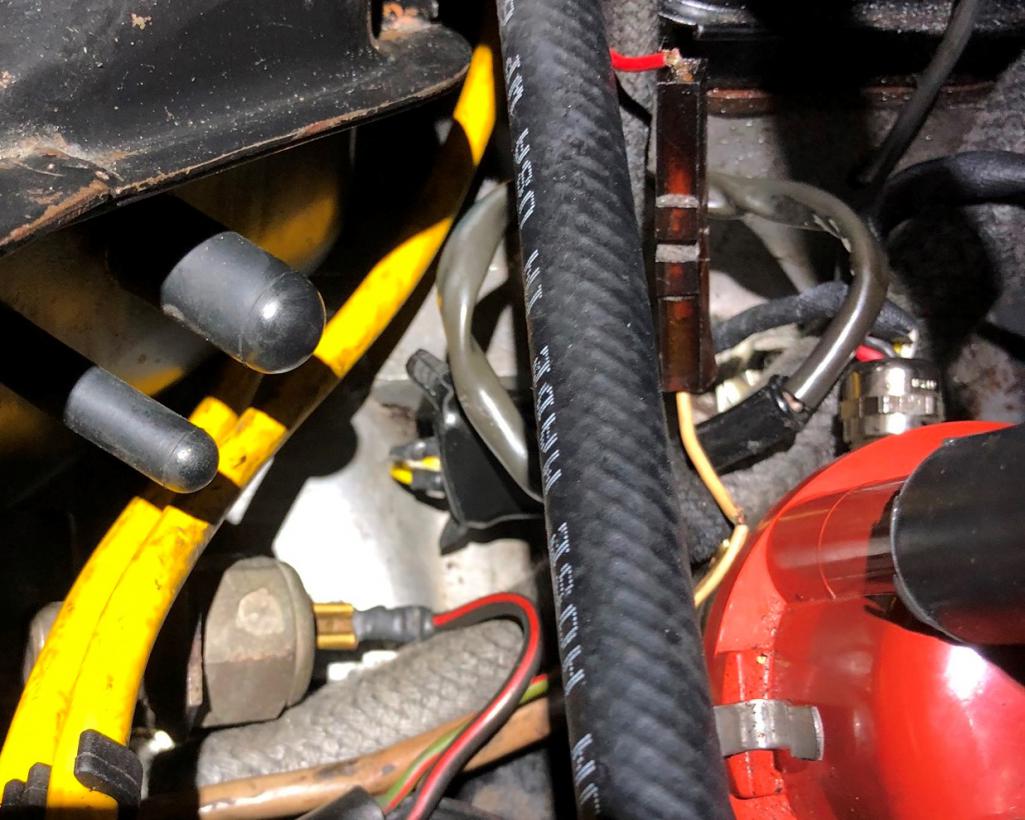 |
   |

 
|
| Rand |
Jul 26 2019, 03:39 PM
Post
#22
|
|
Cross Member Group: Members Posts: 7,409 Joined: 8-February 05 From: OR Member No.: 3,573 Region Association: None |
I keep hearing about cracked plenums. It is rarely the answer. Be honest, has repairing a cracked plenum really solved your problems? It's almost always something else. Throw some tape over your supposed cracks and report back. It's always something else.
|
|
|
|
| Morrie |
Jul 29 2019, 11:37 AM
Post
#23
|
|
Member Group: Members Posts: 181 Joined: 8-October 07 From: Cedar Park, Texas Member No.: 8,198 Region Association: Southwest Region |
I am afraid my question about the wiring got covered up by the semi-useful comment about the plenum. I will say that there was a small leak around the welded on fitting for one of the runners on mine. I cleaned it up while it was off and ran a bead of JB Weld around it for security and confidence.
Anyhow... any help for the wiring question above would be appreciated now. Appreciate comments on the connections... primarily the wire I show going to the thermotime switch. If not that wire, then which one? thanks!! |
|
|
|
| JeffBowlsby |
Jul 29 2019, 01:06 PM
Post
#24
|
|
914 Wiring Harnesses Group: Members Posts: 8,575 Joined: 7-January 03 From: San Ramon CA Member No.: 104 Region Association: None |
I responded to that above. Where does your beach/red wire originate?
|
|
|
|
| Morrie |
Aug 17 2019, 11:43 AM
Post
#25
|
|
Member Group: Members Posts: 181 Joined: 8-October 07 From: Cedar Park, Texas Member No.: 8,198 Region Association: Southwest Region |
QUOTE(JeffBowlsby @ Jul 29 2019, 02:06 PM) I responded to that above. Where does your beach/red wire originate? Hi Jeff, I had some time to trace wiring. The black wire with red stripe you see in the picture is part of the ignition harness. I printed out your 73-76 D-Jet Ignition Harness Diagram and used it for a reference. On my car, the black wire with red stripe originates at the relay board on pin 12, which maps to the AAR, so in this picture the wire is connected incorectly to the thermotime switch. The white wire you see with the crack in the insulation originates in the FI harness. I'm a little confused by the wiring diagram for the FI harness of a 75-76 GC engine code. It appears as if in the diagram the thermotime switch goes to both pins 32 and 33. Does this mean that the 18/33 connection on the 4 pin connector of the relay board, the Thermotime switch, and the cold start injector are all connected? It looks like there is a series connection from 31 on the relay board connector to 31 on the cold start valve, then out of the cold start valve on 32 to the thermotime switch which is connected in parallel with pin 33 on the relay board. Do I have that right? Thanks again for the help! Morrie |
|
|
|
| sholman5 |
Aug 17 2019, 12:24 PM
Post
#26
|
|
Kraut burner Group: Members Posts: 189 Joined: 11-September 16 From: Ormond beach, Fl. Member No.: 20,391 Region Association: South East States |
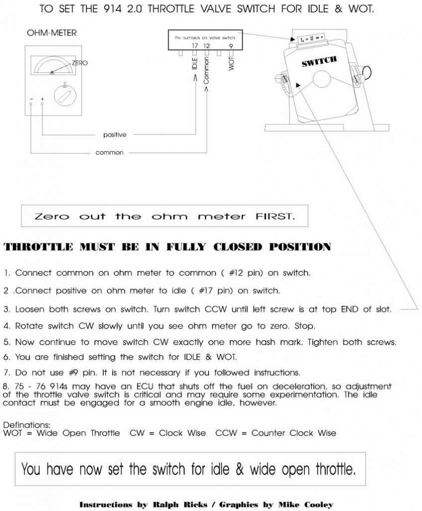
Throttle position switch?
 |
|
|
|
| Morrie |
Aug 17 2019, 12:58 PM
Post
#27
|
|
Member Group: Members Posts: 181 Joined: 8-October 07 From: Cedar Park, Texas Member No.: 8,198 Region Association: Southwest Region |
QUOTE(sholman5 @ Aug 17 2019, 01:24 PM) Throttle position switch? adjusted and re-checked. Since my original post- Adjusted throttle position sensor after disassembly, inspection, cleaning and testing. Identified the MPS as being for a 1973. Sourced a 1973 ECU to match. Set fuel pressure to spec (was about 3 pounds high) Smoked and corrected air leaks in manifold. New Spark plugs and spark plug wires All new engine compartment fuel lines. cleaned and tightened the EFI harness ground bundle. Cleaned and tested the AAR. I was able to get a few notes from two owners ago about what was done when the engine was built. These are some notes provided to the owner ahead of me when he bought the car, and unfortunately I do not have anything more. Take it for what its worth.... "**** did a special engine rebuild. It's balanced and blue printed motor. Makes a honest 120 h.p. I was going to autocross that car, so I wanted everything that a stock class motor could have. I even had $**** throttle body mods done. It breaths better than stock 2.0, some minor head work, just port matching only. That's all the rules would allow. I traded out $***** worth of work to have ** build that motor. That was back in 1993 or so." 1993 sounds like a long time ago. This car sat and sat and sat. Everything was sticky from sitting, connections, etc... since then I have put about 2000 miles on it and aside from what looks like lean plugs, the car runs fantastic when going down the road is is very quick for a 2.0l car supposedly with stock displacement. |
|
|
|
| JeffBowlsby |
Aug 17 2019, 09:31 PM
Post
#28
|
|
914 Wiring Harnesses Group: Members Posts: 8,575 Joined: 7-January 03 From: San Ramon CA Member No.: 104 Region Association: None |
QUOTE(Morrie @ Aug 17 2019, 10:43 AM) QUOTE(JeffBowlsby @ Jul 29 2019, 02:06 PM) I responded to that above. Where does your beach/red wire originate? Hi Jeff, I had some time to trace wiring. The black wire with red stripe you see in the picture is part of the ignition harness. I printed out your 73-76 D-Jet Ignition Harness Diagram and used it for a reference. On my car, the black wire with red stripe originates at the relay board on pin 12, which maps to the AAR, so in this picture the wire is connected incorectly to the thermotime switch. The white wire you see with the crack in the insulation originates in the FI harness. I'm a little confused by the wiring diagram for the FI harness of a 75-76 GC engine code. It appears as if in the diagram the thermotime switch goes to both pins 32 and 33. Does this mean that the 18/33 connection on the 4 pin connector of the relay board, the Thermotime switch, and the cold start injector are all connected? It looks like there is a series connection from 31 on the relay board connector to 31 on the cold start valve, then out of the cold start valve on 32 to the thermotime switch which is connected in parallel with pin 33 on the relay board. Do I have that right? Thanks again for the help! Morrie Hey Morrie: I have seen only one other 73-76 Ignition harness with that black/red AAR valve wire, most typically they are white. So I think you solved that mystery. Cnfimring, the relay board, the thermotime switch, and the cold start injector are all connected for the 75-76 cars only. It is as you say. |
|
|
|
| rjames |
Aug 17 2019, 11:27 PM
Post
#29
|
|
I'm made of metal Group: Members Posts: 3,996 Joined: 24-July 05 From: Shoreline, WA Member No.: 4,467 Region Association: Pacific Northwest |
Fix any vacuum leaks first.
Then I would adjust the MPS. If you are running lean and all else is good, it likely needs to be adjusted, especially if it wasn’t originally mated with your engine, or your engine isn’t stock. I just went through this myself. |
|
|
|
| Morrie |
Sep 30 2019, 04:08 PM
Post
#30
|
|
Member Group: Members Posts: 181 Joined: 8-October 07 From: Cedar Park, Texas Member No.: 8,198 Region Association: Southwest Region |
I thought I would share an update, and mention the last issue I am seeing. The car is running very well now. I am running a 73 ECU and MPS with a breather box that has the correct (NOS) PCV valve installed and the engine starts and runs well. Timing is set and verified, I am running a 123 Distributor currently.
One ongoing issue throughout all this is the cold idle. The AAR has been tested and opens and closes with temperature. If I plug its intake with a cold engine, the engine stalls so I know it is helping. My cold idle speed, however is still very low, sub 1000 RPMs, in the range of 500-700 RPMs. If I unplug the output side of the AAR that leads to the CSV and allow the hose to go to open air on the line feeding the CSV, the idle comes up as you would expect, around 2000RPMs. The input side of the AAR is plumbed to the air cleaner. When fully warmed, my idle is about 1000RPMs. I sent the MPS off to Chris at Tangerine and he went through it. He verified that the diaphragm was in good condition. He enriched the mixture slightly as is his normal process, and this has made a positive difference. I have not been able to get a bung welded into the header yet for my LM1, though the MPS is now converted by Chris to be externally adjustable. Any thoughts? Is it normal for there to be at least some restriction in the AAR when cold? I have three of them and they all seem to perform the same. |
|
|
|
| rjames |
Sep 30 2019, 06:02 PM
Post
#31
|
|
I'm made of metal Group: Members Posts: 3,996 Joined: 24-July 05 From: Shoreline, WA Member No.: 4,467 Region Association: Pacific Northwest |
What rpms does it idle at when warm?
Timing set correctly? Did you calibrate your mps yet? Sounds like the AAR isn’t opening enough or... is it connected correctly l? The opening facing the passenger side should be connected to the air cleaner box. |
|
|
|
| JeffBowlsby |
Sep 30 2019, 07:04 PM
Post
#32
|
|
914 Wiring Harnesses Group: Members Posts: 8,575 Joined: 7-January 03 From: San Ramon CA Member No.: 104 Region Association: None |
I think the last two posts are discussing the aux air regulator (air), not the cold start valve (fuel)
|
|
|
|
| JeffBowlsby |
Sep 30 2019, 07:05 PM
Post
#33
|
|
914 Wiring Harnesses Group: Members Posts: 8,575 Joined: 7-January 03 From: San Ramon CA Member No.: 104 Region Association: None |
Dbl post, sorry.
|
|
|
|
| Morrie |
Sep 30 2019, 07:51 PM
Post
#34
|
|
Member Group: Members Posts: 181 Joined: 8-October 07 From: Cedar Park, Texas Member No.: 8,198 Region Association: Southwest Region |
QUOTE(JeffBowlsby @ Sep 30 2019, 08:04 PM) I think the last two posts are discussing the aux air regulator (air), not the cold start valve (fuel) That's what I get for writing rapidly at the end of the day. Apologies for the brain fog and lack of clarity. I edited my post, but you are right Jeff, I meant AAR, not CSV. |
|
|
|
| Morrie |
Sep 30 2019, 07:55 PM
Post
#35
|
|
Member Group: Members Posts: 181 Joined: 8-October 07 From: Cedar Park, Texas Member No.: 8,198 Region Association: Southwest Region |
QUOTE(rjames @ Sep 30 2019, 07:02 PM) What rpms does it idle at when warm? Timing set correctly? Did you calibrate your mps yet? Sounds like the CSV isn’t opening enough or... is it connected correctly l? The opening facing the passenger side should be connected to the air cleaner box. I updated my post above with corrections and some more info. I have verified the CSV is hooked up correctly, timing is correct, but I have not calibrated the MPS yet. I know that is a key part of the puzzle but still seems odd that the additional air from the CSV isnt sufficient where just opening the line is. I've verified the CSV (not AAR) isn't leaking fuel, but have not verified if it is injecting fuel or not. I should pull the plug on it right after starting and see if there is a negative effect..... |
|
|
|
| rjames |
Sep 30 2019, 08:25 PM
Post
#36
|
|
I'm made of metal Group: Members Posts: 3,996 Joined: 24-July 05 From: Shoreline, WA Member No.: 4,467 Region Association: Pacific Northwest |
QUOTE(Morrie @ Sep 30 2019, 06:51 PM) QUOTE(JeffBowlsby @ Sep 30 2019, 08:04 PM) I think the last two posts are discussing the aux air regulator (air), not the cold start valve (fuel) That's what I get for writing rapidly at the end of the day. Apologies for the brain fog and lack of clarity. I edited my post, but you are right Jeff, I meant AAR, not CSV. I meant the AAR too. (IMG:style_emoticons/default/smile.gif) I corrected my previous post (which still applies - you may have an AAR that isn’t opening, or it’s hooked up backwards (unlikely). |
|
|
|
| Bleyseng |
Oct 1 2019, 09:31 AM
Post
#37
|
|
Aircooled Baby! Group: Members Posts: 13,035 Joined: 27-December 02 From: Seattle, Washington (for now) Member No.: 24 Region Association: Pacific Northwest |
As I read it you are now running the 73 2.0L Djet setup with 037 ECU and 037MPS? What about the CHT as it needs to be the 017 73 2.0L only one with 280 ohm resistor for it to idle right.
|
|
|
|
| ChrisFoley |
Oct 1 2019, 11:36 AM
Post
#38
|
|
I am Tangerine Racing Group: Members Posts: 7,937 Joined: 29-January 03 From: Bolton, CT Member No.: 209 Region Association: None |
QUOTE(Morrie @ Sep 30 2019, 05:08 PM) ... He enriched the mixture slightly as is his normal process, and this has made a positive difference. I have not been able to get a bung welded into the header yet for my LM1, though the MPS is now converted by Chris to be externally adjustable. ... My suggestion is to make an additional smaller adjustment in the same direction I made the first one. I backed the center screw out one full turn. Go another quarter turn and see if the engine seems to like it. |
|
|
|
| Morrie |
Oct 1 2019, 04:23 PM
Post
#39
|
|
Member Group: Members Posts: 181 Joined: 8-October 07 From: Cedar Park, Texas Member No.: 8,198 Region Association: Southwest Region |
QUOTE(ChrisFoley @ Oct 1 2019, 12:36 PM) My suggestion is to make an additional smaller adjustment in the same direction I made the first one. I backed the center screw out one full turn. Go another quarter turn and see if the engine seems to like it. Hey Chris, Thanks again for checking out the MPS and making it externally adjustable for me. There was an immediate improvement in how the engine runs, as you suspected. I'll give it another quarter turn and report back. Thanks again! |
|
|
|
| ConeDodger |
Oct 1 2019, 04:27 PM
Post
#40
|
|
Apex killer! Group: Members Posts: 23,631 Joined: 31-December 04 From: Tahoe Area Member No.: 3,380 Region Association: Northern California |
QUOTE(ChrisFoley @ Jul 1 2019, 01:35 PM) QUOTE(914_teener @ Jul 1 2019, 10:48 AM) This needs to be investgated and checked or you will chase your tail. (IMG:style_emoticons/default/agree.gif) Cracked plenums can have a big effect on idle performance, when manifold vacuum is high and total air load is small. Shine a light through it in a darkened room. They also develop pinhole rust through. |
|
|
|
|
1 User(s) are reading this topic (1 Guests and 0 Anonymous Users)
0 Members:

|
Lo-Fi Version | Time is now: 26th June 2024 - 01:37 AM |
Invision Power Board
v9.1.4 © 2024 IPS, Inc.