|
|

|
Porsche, and the Porsche crest are registered trademarks of Dr. Ing. h.c. F. Porsche AG.
This site is not affiliated with Porsche in any way. Its only purpose is to provide an online forum for car enthusiasts. All other trademarks are property of their respective owners. |
|
|
  |
| Montreal914 |
 May 28 2023, 09:11 PM May 28 2023, 09:11 PM
Post
#121
|
|
Senior Member    Group: Members Posts: 1,700 Joined: 8-August 10 From: Claremont, CA Member No.: 12,023 Region Association: Southern California 
|
Another month goes by... (IMG:style_emoticons/default/blink.gif)
After a trip to Portugal where we enjoyed a lot of wine, especially Port and Pastel de Nata (IMG:style_emoticons/default/smile.gif) , time to get back to work! (IMG:style_emoticons/default/smash.gif) Before tackling any more cutting of the frame, it was time to complete the work on the Jigster (Jeff Hail's TM (IMG:style_emoticons/default/beerchug.gif) ). Using the horizontal and vertical laser, I set the Jigster leveled and made sure the car was not only leveled, but also on the center line of the Jigster. Then I did a bunch of Z axis measurement to see how things were. I was happily surprised to see that everything was within about 1/32"! (IMG:style_emoticons/default/sunglasses.gif). This was encouraging despite all of the recent rust findings. I also measure the lower edge of the car's back panel and it was the same on both sides. This has been a concern since seeing the car had been hit in the back. 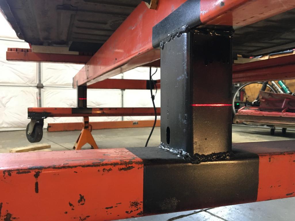 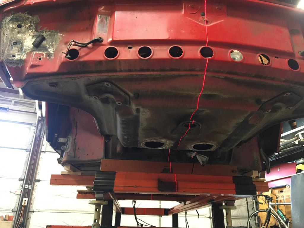 Up to this point the car had been resting on wooden 2"x2" under the longs. If I am to start cutting the structure, I need to make sure things are held. Time to bolt the car to the Jigster! (IMG:style_emoticons/default/smile.gif) With the car and Jigster now perfectly leveled and centered, I fabricated brackets, then bolted them to the car's front suspension cross member rear mounting point and welded them to a cross beam. 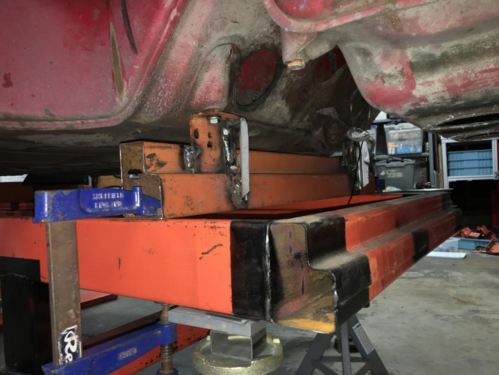 Then similarly in the back, I made brackets and mounted them to the engine mounts, and with 1/2" threaded rods adjusted them and welded/tightened everything. The car is now well attached to the Jigster, almost ready for some structural work. 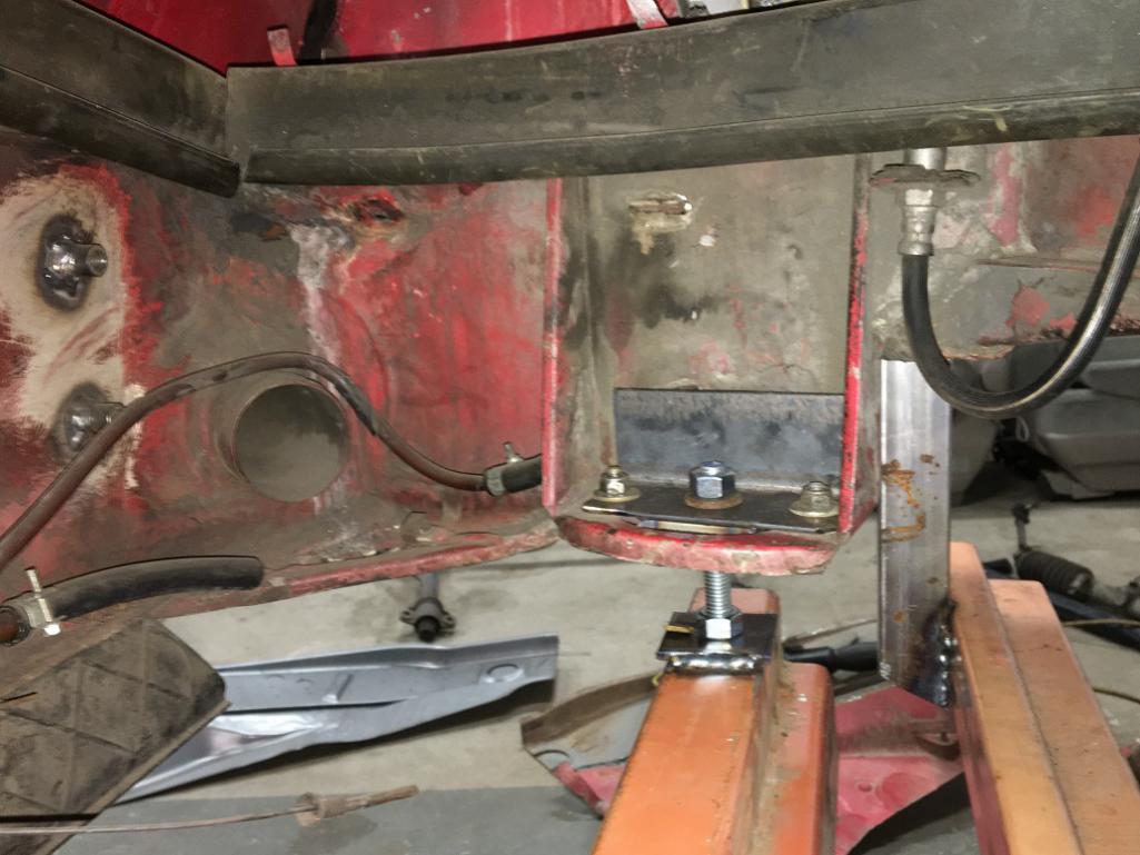 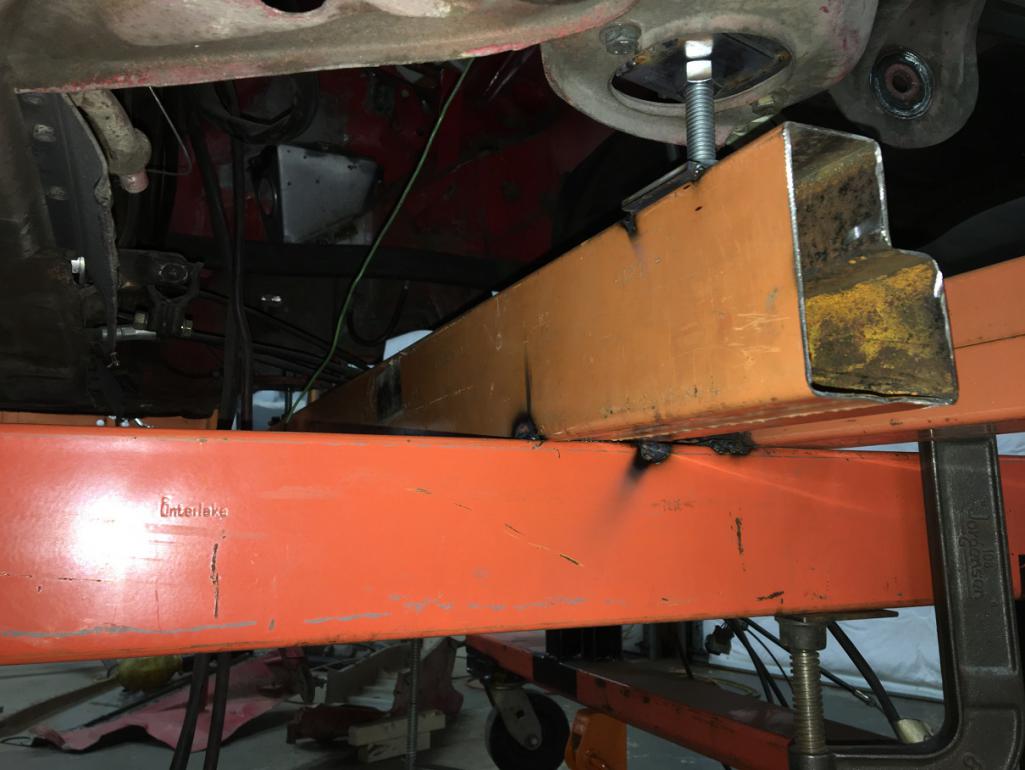 Yes, almost ready because bracing is the next important part! I built these using 1"x1"x1/8" square tubes and 3/4" turnbuckles. 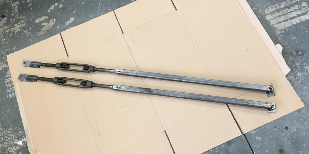 Now installed on the tub 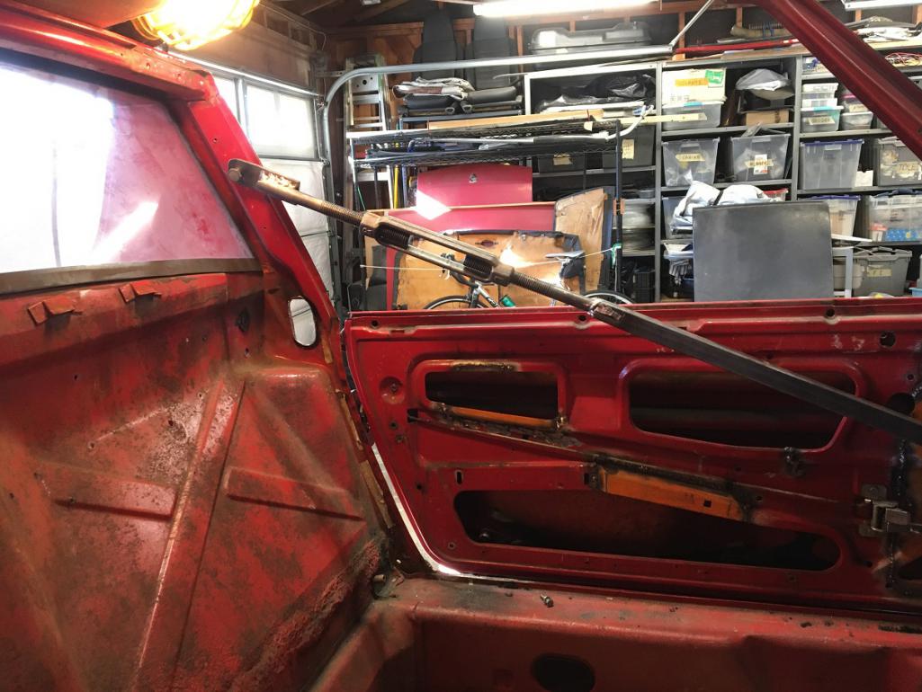 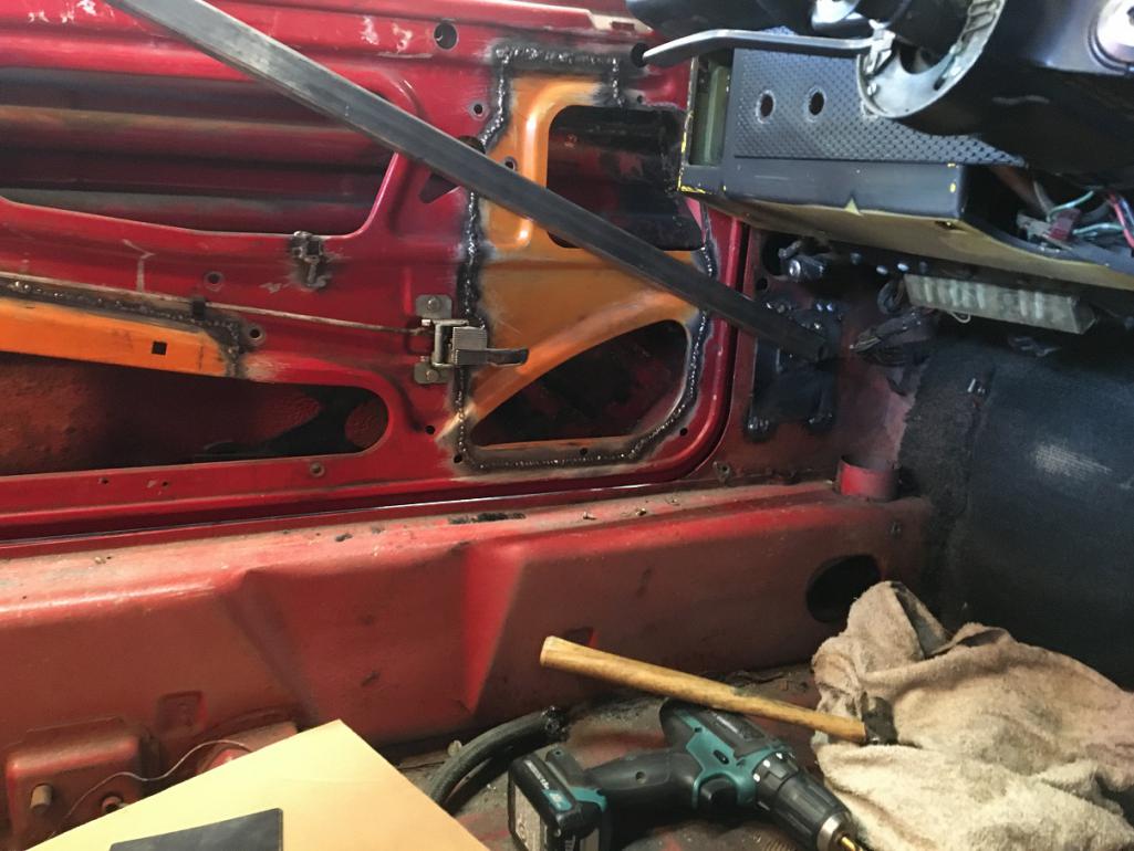 Then I decided to add another one on the bottom. Not sure it is needed, but anyhow, it is there... (IMG:style_emoticons/default/biggrin.gif) 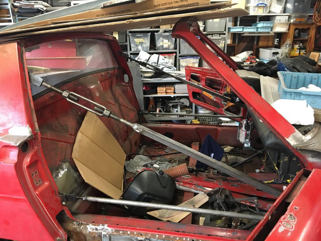 Note that all these braces can easily be removed by unscrewing the bolts at each ends. Also, doors are kept on the car and can open or close freely to ensure constant gap monitoring. |
| Montreal914 |
 May 29 2023, 10:30 AM May 29 2023, 10:30 AM
Post
#122
|
|
Senior Member    Group: Members Posts: 1,700 Joined: 8-August 10 From: Claremont, CA Member No.: 12,023 Region Association: Southern California 
|
To address the rust on the driver's side long, I will need to remove the rear suspension outer console. In order to reinstall it, I need a jig to locate the mounting points.
I prepared a couple of 1/4" plate using the "L" piece that goes in the suspension assembly as a template for my holes. 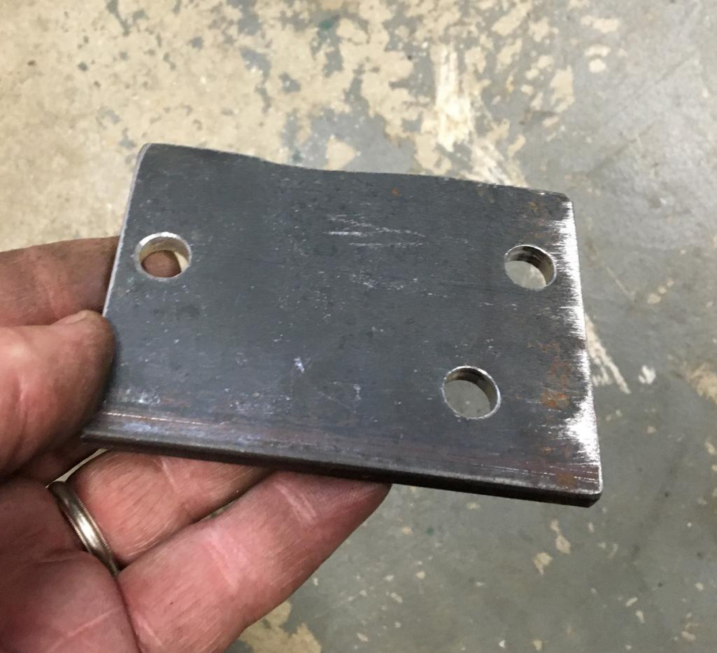 Once bolted to the chassis, I built a jig mounted to the Jigster. The cross beam has left-right stoppers, and there are also angle stoppers to the Jigster longitudinal frame as front-back locating point. The cross beam is then clamped to the Jigster. 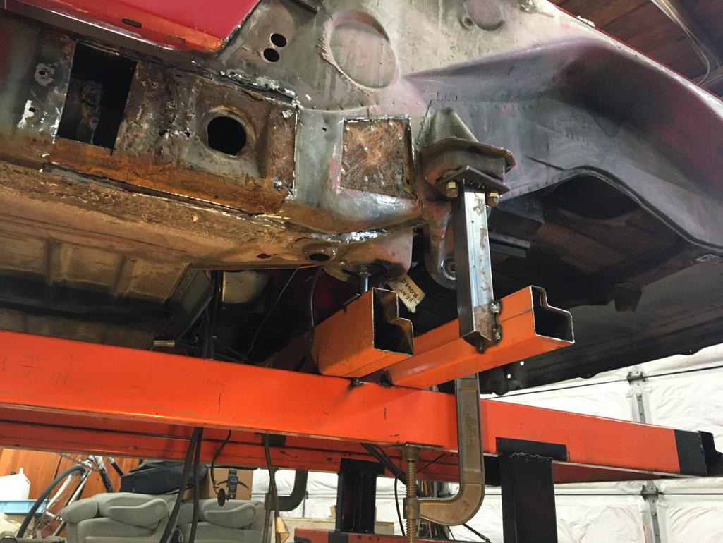 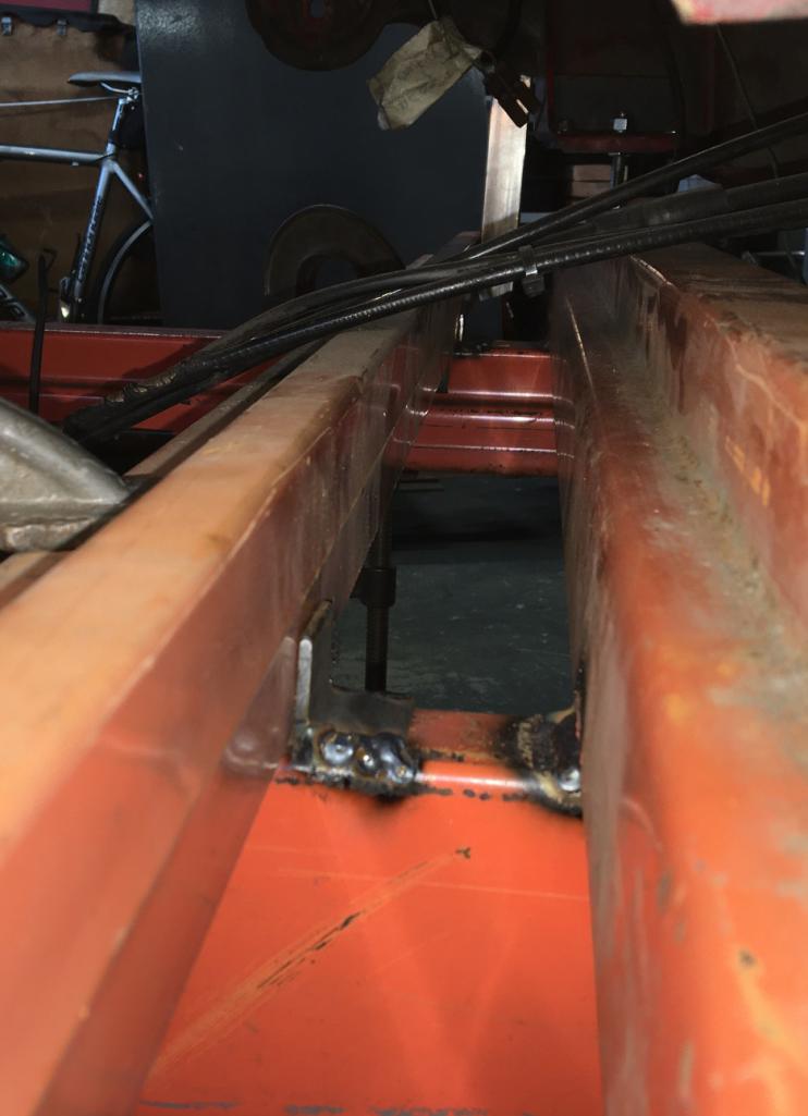 To remove the outer suspension point jig, I unscrew the six suspension bolts, Remove the large clamps, slide the cross beam with jig backward, tilt backwards, and remove. Important to note that I will not remove both outer suspension point simultaneously (driver's and passenger's side) so at least one of the two suspension mounting point will be on the car when one is removed as an added reference. Next, I started dismantling the donor part I recently got from Vince. Anyone who has dealt with these rear suspension factory braces know how much of a pain they are to remove... (IMG:style_emoticons/default/headbang.gif) 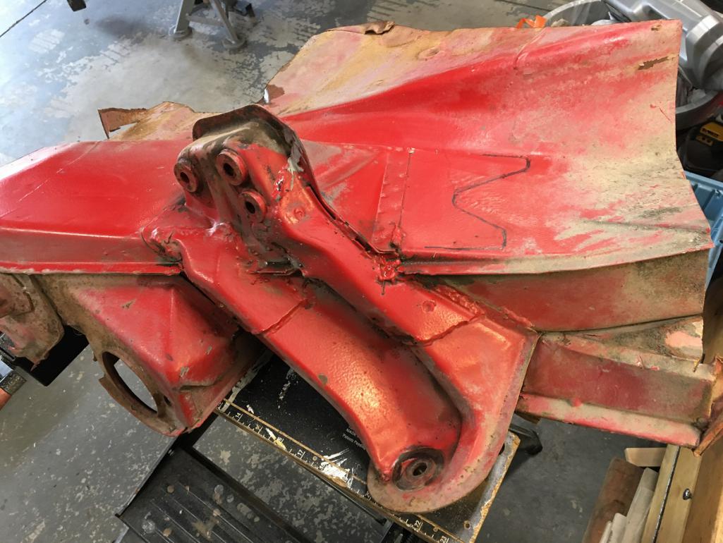 As if all of the perimeter welds weren't enough on the longer brace, there are 2 large plug welds to deal with... (IMG:style_emoticons/default/rolleyes.gif) 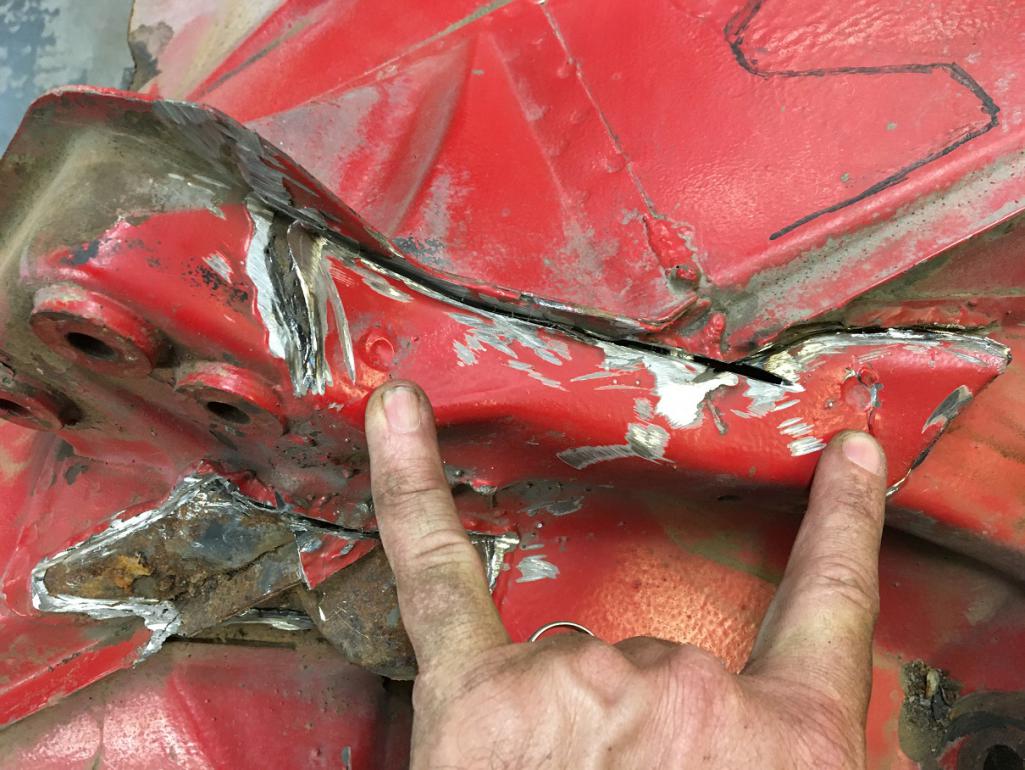 After spending about 3 hours of delicate grinding and drilling, I was able to separate the inner and outer portion of donor driver side rear longitudinal. 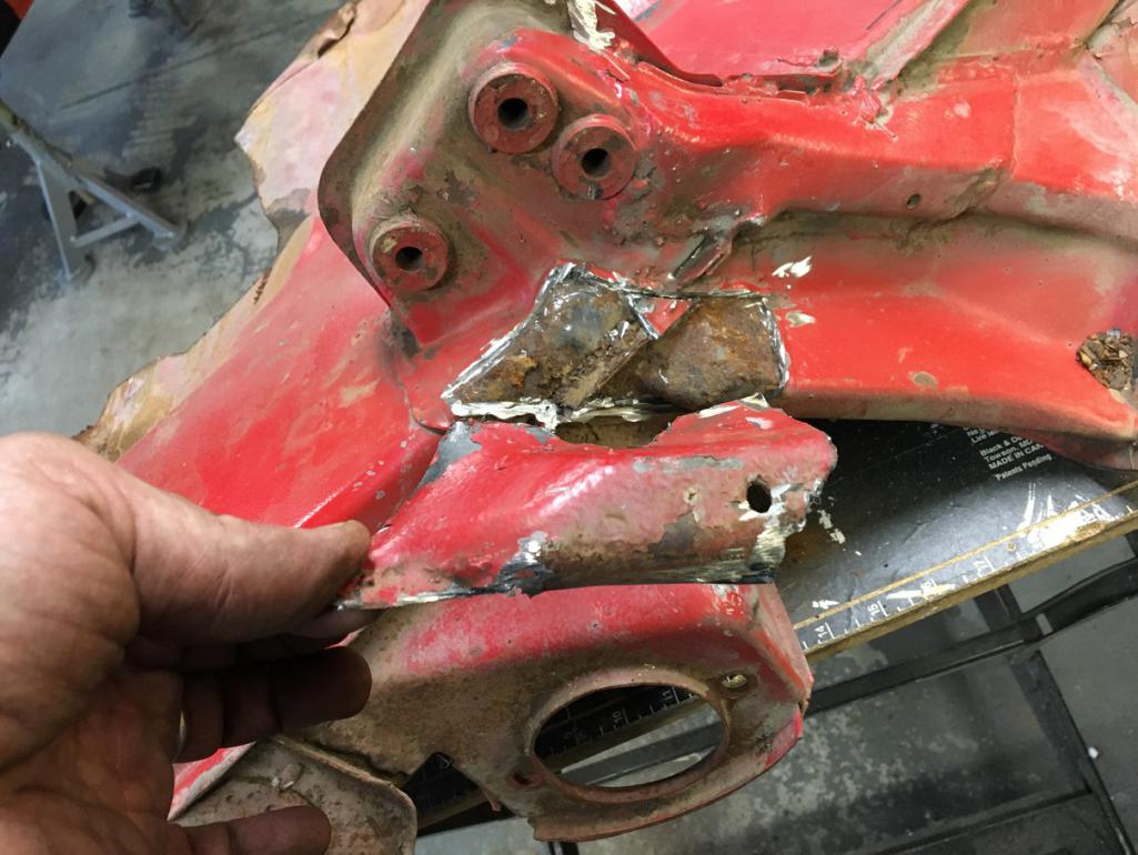 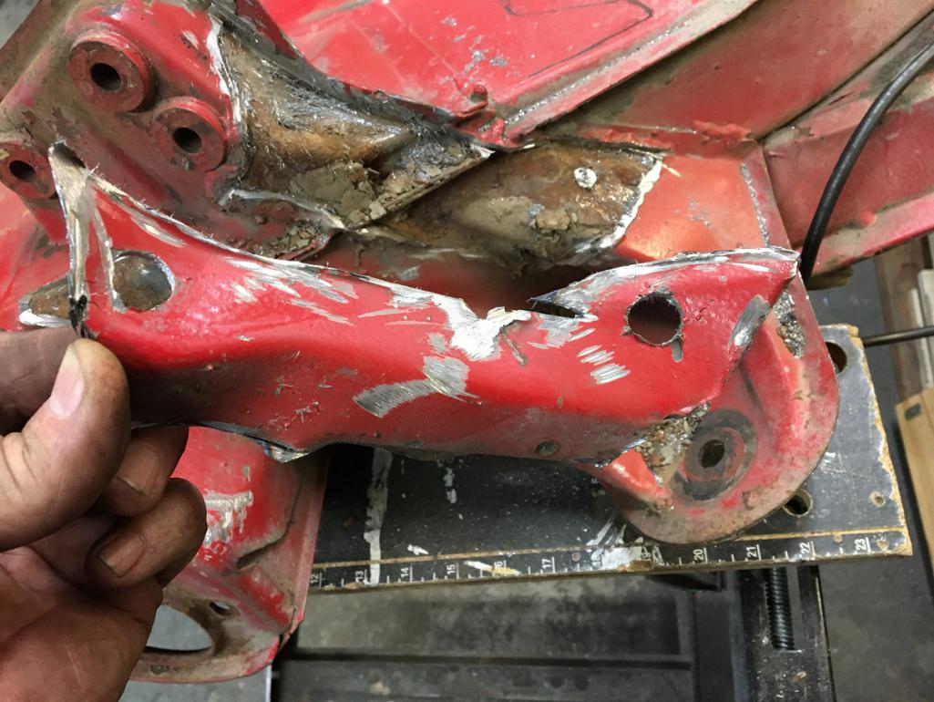 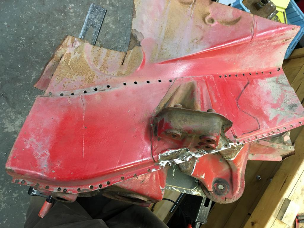 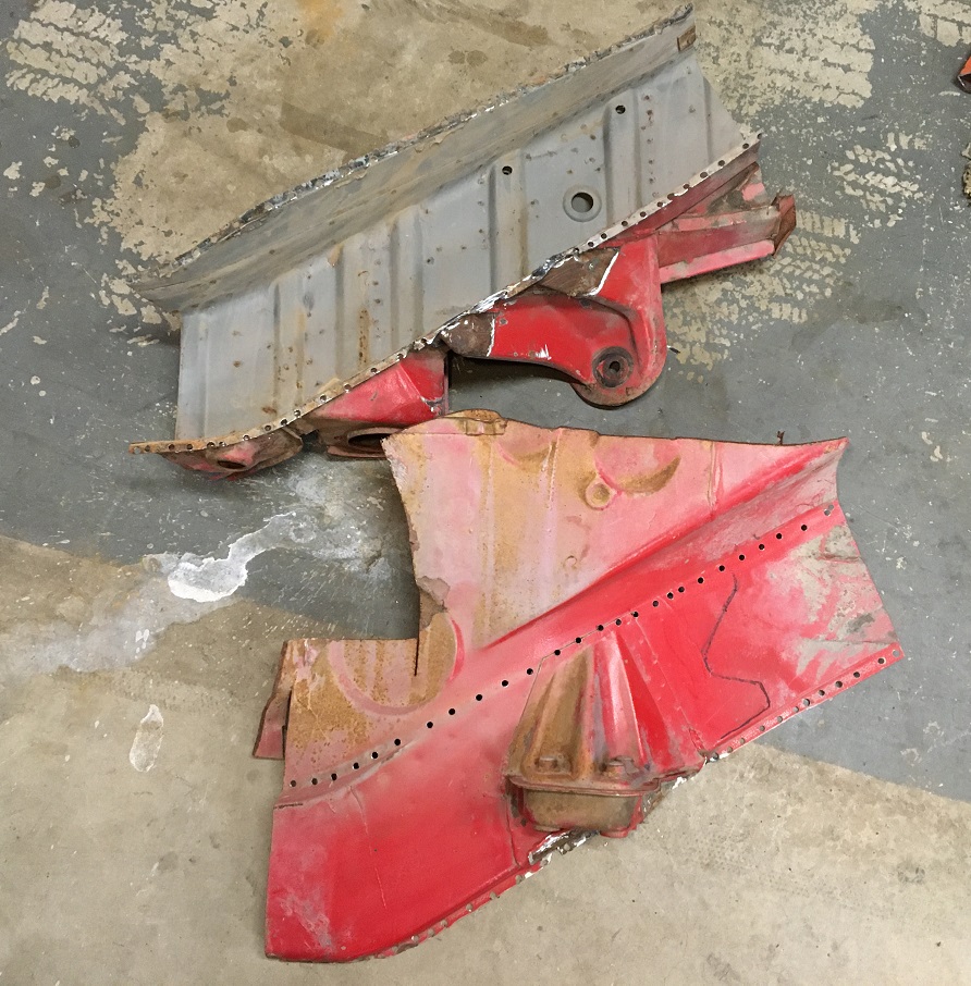 I am very happy with the condition of these old parts! All but healthy and solid metal! (IMG:style_emoticons/default/cheer.gif) (IMG:style_emoticons/default/sunglasses.gif) More pictures in next post... Not sure why this picture is repeated below... (IMG:style_emoticons/default/confused24.gif) Attached thumbnail(s) 
|
| Montreal914 |
 May 29 2023, 10:54 AM May 29 2023, 10:54 AM
Post
#123
|
|
Senior Member    Group: Members Posts: 1,700 Joined: 8-August 10 From: Claremont, CA Member No.: 12,023 Region Association: Southern California 
|
More pictures (IMG:style_emoticons/default/biggrin.gif)
Here is the back side of the outer long. This will be a nice replacement to the rusty area of my car. (IMG:style_emoticons/default/smile.gif) 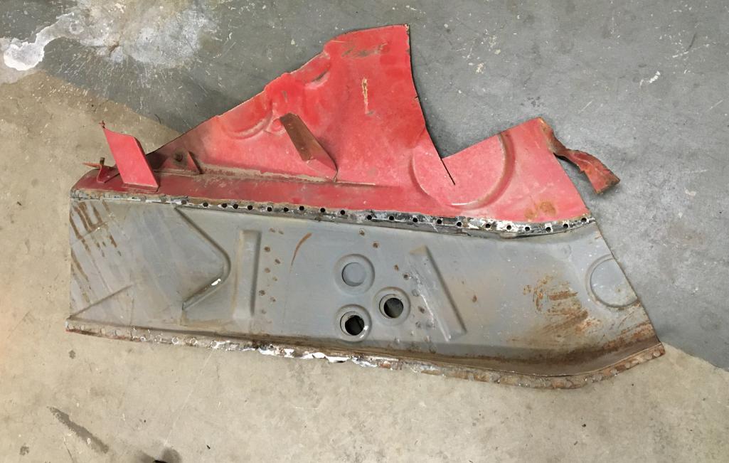 For those who aren't aware, unfortunately, the driver side of this part isn't available as a replacement part from Restoration Design of other vendors. So, I am very pleased with this finding! Left is driver side, right is new RD passenger side. (IMG:style_emoticons/default/smilie_pokal.gif) 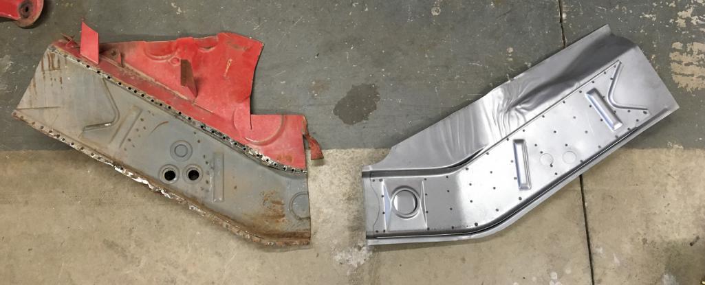 Looking at the port holes, I was able to take a few pictures to show the inside of the suspension console. These can be quite rusty at times, but this one is clearly in excellent shape. I will probably flush it with Ospho and spray some Eastwood chassis protection in it. 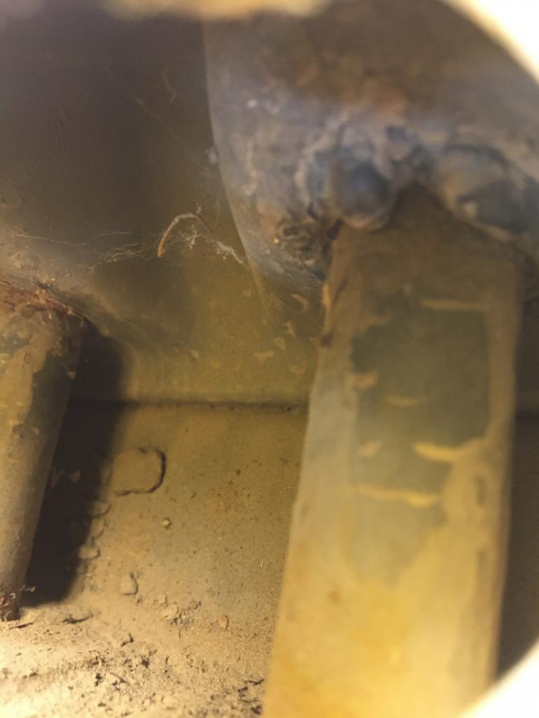 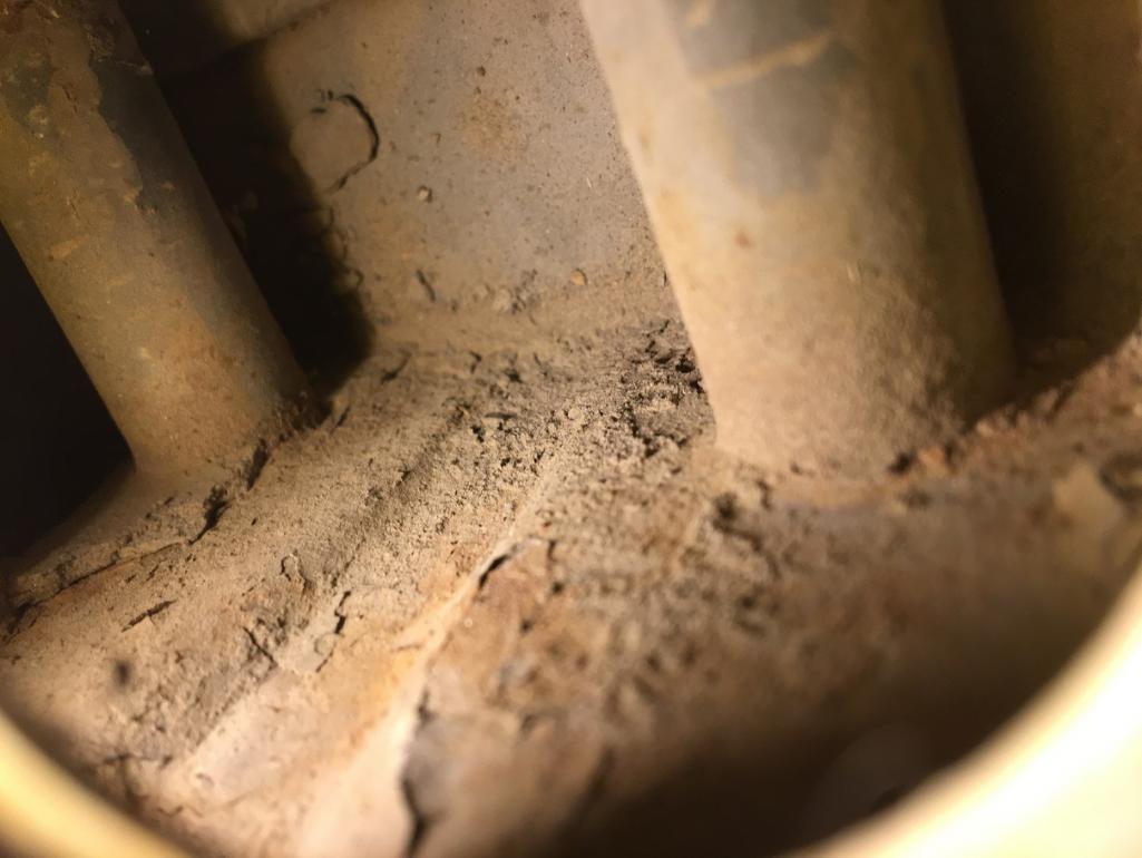 As a reminder, the reason I am going through all of this is to fix this... (IMG:style_emoticons/default/unsure.gif) From the outside, the metal on that elbow seems pretty solid. 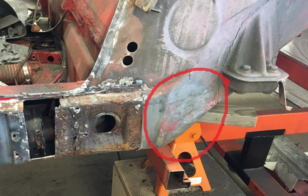 But once I looked into it, I found this crusty rusted and soft metal that I was able to punch through with a screwdriver near the suspension console area. That is a key structural area of our cars! 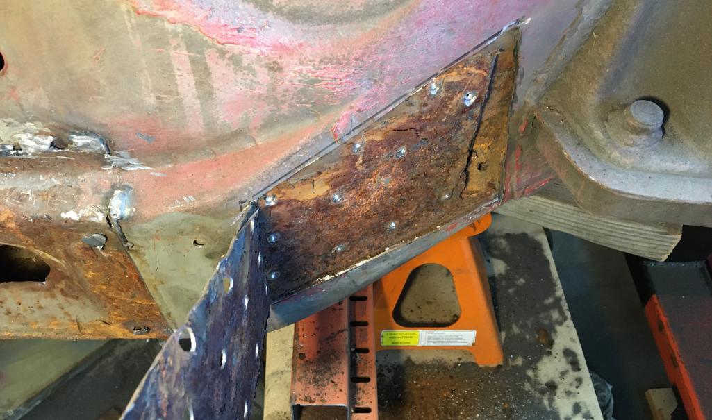 |
| nivekdodge |
 May 29 2023, 07:05 PM May 29 2023, 07:05 PM
Post
#124
|
|
Member   Group: Members Posts: 273 Joined: 28-August 21 From: Pittsburgh Pa Member No.: 25,860 Region Association: MidAtlantic Region 
|
Holy toledo. You are going to town on that.
Kevin |
| Mayne |
 May 30 2023, 09:40 AM May 30 2023, 09:40 AM
Post
#125
|
|
Member   Group: Members Posts: 254 Joined: 28-February 17 From: NM Member No.: 20,880 Region Association: None |
Nice work! Are you going to coat the inside of your patch panels with something?
|
| 930cabman |
 May 30 2023, 12:15 PM May 30 2023, 12:15 PM
Post
#126
|
|
Advanced Member     Group: Members Posts: 3,695 Joined: 12-November 20 From: Buffalo Member No.: 24,877 Region Association: North East States 
|
This is great progress, thank you for documenting
(IMG:style_emoticons/default/cheer.gif) (IMG:style_emoticons/default/cheer.gif) (IMG:style_emoticons/default/cheer.gif) (IMG:style_emoticons/default/cheer.gif) (IMG:style_emoticons/default/cheer.gif) (IMG:style_emoticons/default/cheer.gif) |
| bkrantz |
 May 30 2023, 07:08 PM May 30 2023, 07:08 PM
Post
#127
|
|
914 Guru      Group: Members Posts: 8,142 Joined: 3-August 19 From: SW Colorado Member No.: 23,343 Region Association: Rocky Mountains 
|
Nice surgical work. Keep going!
|
| Montreal914 |
 Jun 20 2023, 09:04 PM Jun 20 2023, 09:04 PM
Post
#128
|
|
Senior Member    Group: Members Posts: 1,700 Joined: 8-August 10 From: Claremont, CA Member No.: 12,023 Region Association: Southern California 
|
The quest for solid metal continues... (IMG:style_emoticons/default/headbang.gif)
Clearly, both outer layers of the long from the jack point to the outer suspension console are compromised and will have to be removed. (IMG:style_emoticons/default/sawzall-smiley.gif) So here is the plan marked in black. The inner fender will be cut above its junction to the inner layers. Spot welds will be drilled to free the outer layer from the inner. The cut on the back end of the outer long will be done close to the suspension console. The plan will be to use the Attached thumbnail(s) 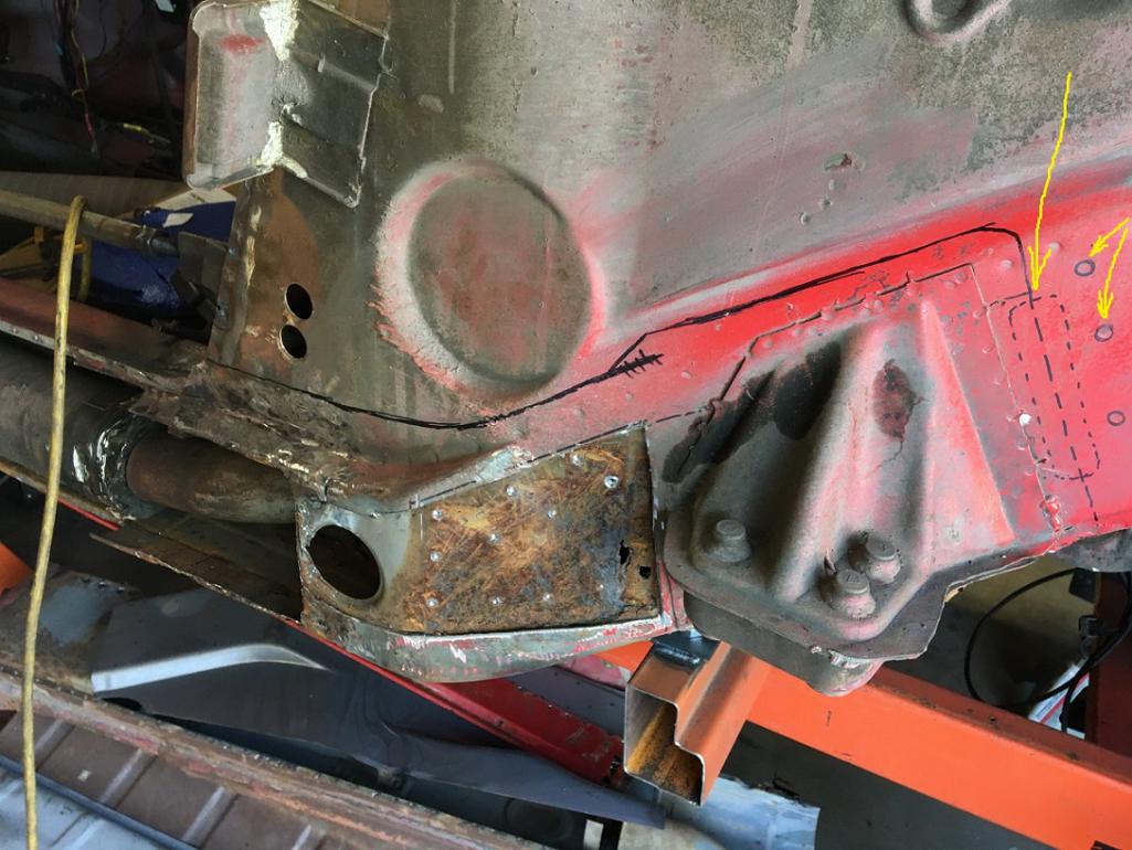
|
| 930cabman |
 Jun 21 2023, 07:32 AM Jun 21 2023, 07:32 AM
Post
#129
|
|
Advanced Member     Group: Members Posts: 3,695 Joined: 12-November 20 From: Buffalo Member No.: 24,877 Region Association: North East States 
|
Will it ever end?
Keep up the good work, there must be and end to it |
| Montreal914 |
 Jun 21 2023, 08:37 AM Jun 21 2023, 08:37 AM
Post
#130
|
|
Senior Member    Group: Members Posts: 1,700 Joined: 8-August 10 From: Claremont, CA Member No.: 12,023 Region Association: Southern California 
|
Right? When will I get to solid metal?? (IMG:style_emoticons/default/wacko.gif)
I accidentally added the previous post as I was composing... Back to the cut of this large piece... The cut on the back end of the outer long (right in the picture) will be done close to the suspension console. The spot welds joining the tail end (V shaped) of the inner layer will be drilled. The plan will be to install the new piece using the inner layer as an overlap. 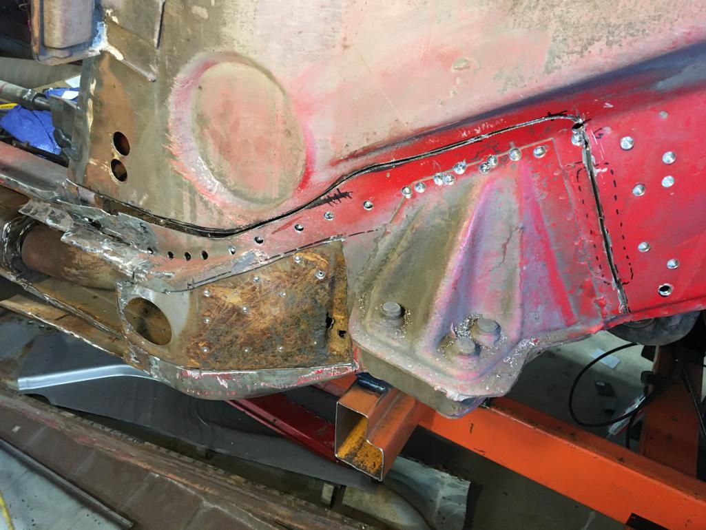 Here we can see the whole piece freed up. Notice the inner layer (V) extending towards the back. The new piece will be installed exactly like that and the inner layer will be plug welded to the outer layer creating a nice staggered ovelaping joint. 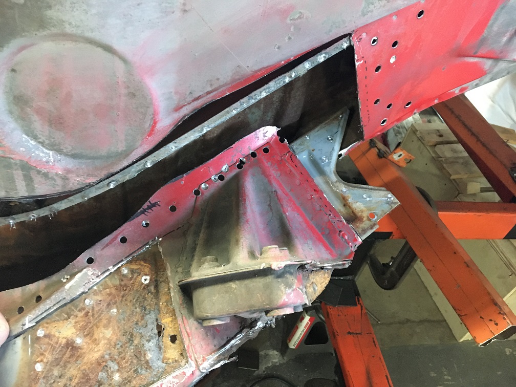 And here is the removed piece. Although the heavily rusted area circled seems small, I am convinced there is a lot more hiding. Did I remove too much material? Could this have been repaired without creating this opening? Maybe, but the outer suspension console would have needed to come out anyway. The benefit of removing the whole panel will be to inspect more easily. 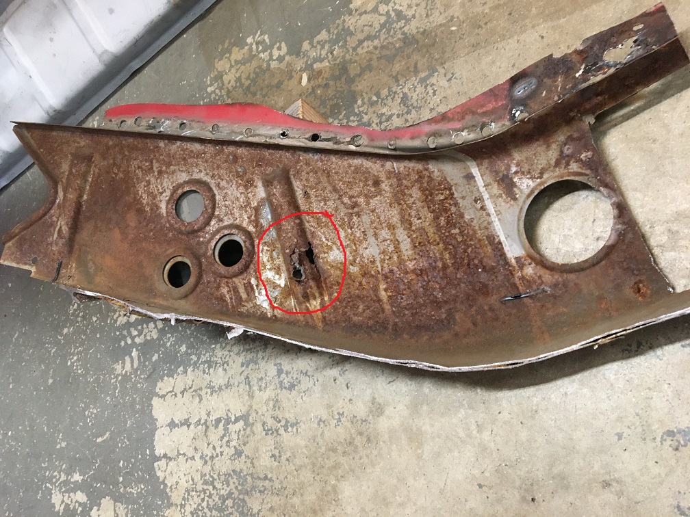 First, let's make a peek hole to see what color is the metal behind... I am definitely liking that nice primer gray color in the hole! 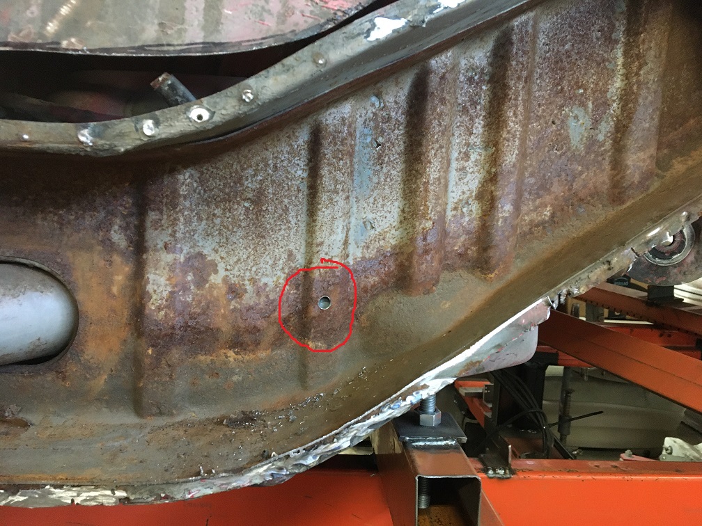 But there are other areas that aren't looking that great... (IMG:style_emoticons/default/dry.gif) 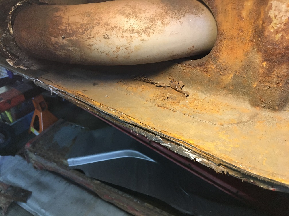 These bumps are always suspicious to me... Clearly rust has pushed the metal up in that area. Investigation will be needed. 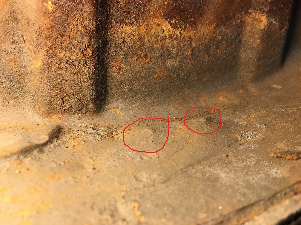 Time to chisel this weak metal off and see what is still good... 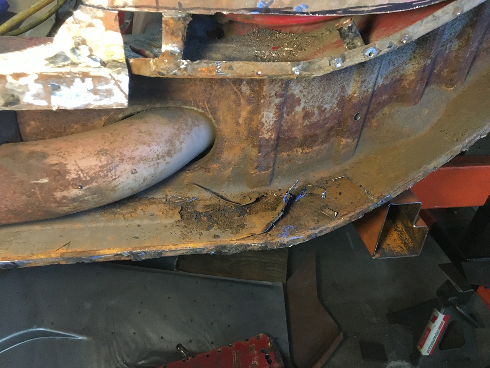 That led to finding weak spots also in the outside inner layer of the long. Again, in order to fully assess the situation, I need to remove more metal. That triangle with the donut will have to come off... 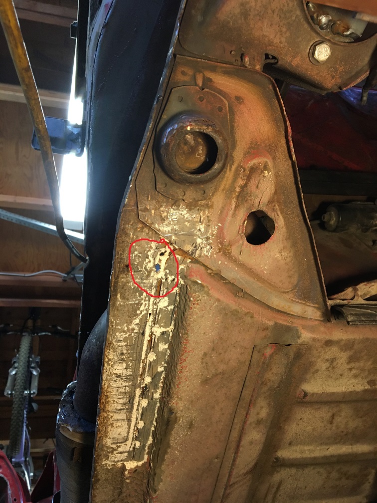 Out it goes... This part will be straightened and reinstalled after the long has been repaired. 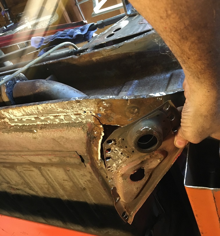 Ah!!! Rust, rust, and more rust... (IMG:style_emoticons/default/rolleyes.gif) 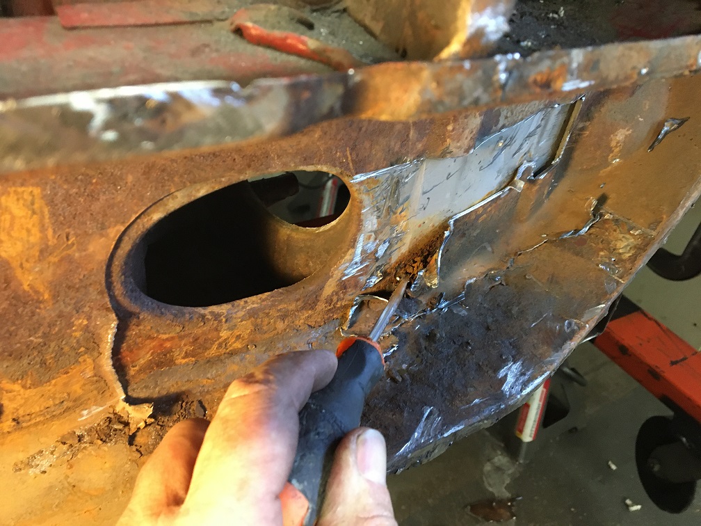 In the end, I removed the whole lower half of the inside inner layer (contoured in yellow), including the lower seat belt anchoring point. Notice the rust hole just behind it... (IMG:style_emoticons/default/unsure.gif) While poking with the screwdriver, it easily went through... I am holding the last piece removed in my hand. All of this was progressively done. But at this point, I do believe the deep rust is ending and the good metal is finally there. I will treat the surface rust and the metal should be sound. 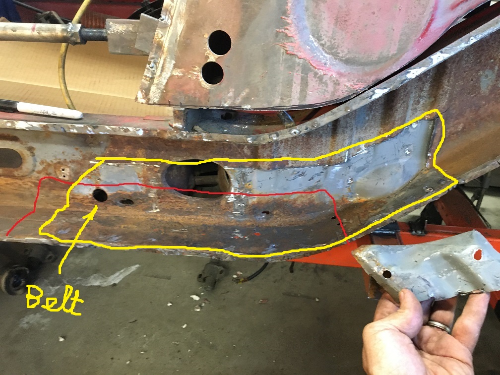 Next step will be to cut at the red line and rebuild the inside outer layer, then add the inside inner layer. Removing that red section will also means detaching that area of the floor, and the flanged lower firewall beam inner and outer panels. More fun to come! (IMG:style_emoticons/default/smash.gif) |
| 930cabman |
 Jun 21 2023, 09:30 AM Jun 21 2023, 09:30 AM
Post
#131
|
|
Advanced Member     Group: Members Posts: 3,695 Joined: 12-November 20 From: Buffalo Member No.: 24,877 Region Association: North East States 
|
AT LAST, good metal
Like finding water in the desert (not really) |
| Montreal914 |
 Jul 13 2023, 10:59 AM Jul 13 2023, 10:59 AM
Post
#132
|
|
Senior Member    Group: Members Posts: 1,700 Joined: 8-August 10 From: Claremont, CA Member No.: 12,023 Region Association: Southern California 
|
Next step, cleaning up the surface rust in the upper long.
So this is the situation now. 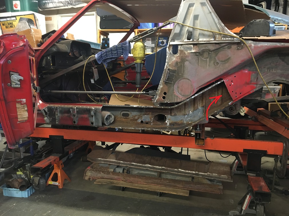 More specifically, I am looking at treating the surface rust in the upward portion to start with. Here! (Note that this picture was taken before I removed the Inside-inner lower portion shown in previous post.) 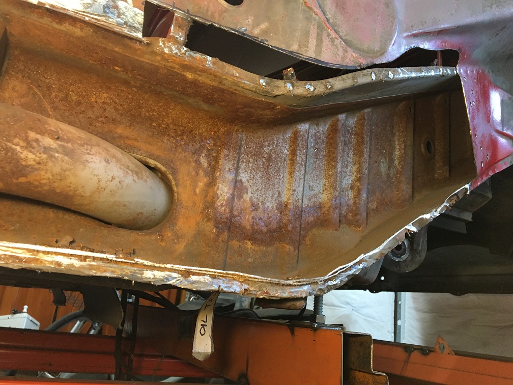 Inspired by @"Alain V." , I found online people using powdered citric acid mixed with water to dissolve rust. (IMG:style_emoticons/default/idea.gif) Looking at the amount of fluid I will need to soak some of these large parts, I decided to try it out! (IMG:style_emoticons/default/stirthepot.gif) Dissolve 2 cups of citric acid with water in a medium pan at medium heat. On the side, fill a tote with 3-4 gallons of water. When powder is dissolved, carefully poor concentrated acid into tote. Now you have a cheap mix of rust dissolving solution. (IMG:style_emoticons/default/sunglasses.gif) After trying overnight with a piece I had, I was pleasantly surprise of how efficient this was. Then I used Alain's setup, got a larger tote, a $20 submersible pump, a hose, and a sprinkler head I had laying around. This is the setup, spraying the citric acid in the long. I started from the top and gradually moved the spray head down. 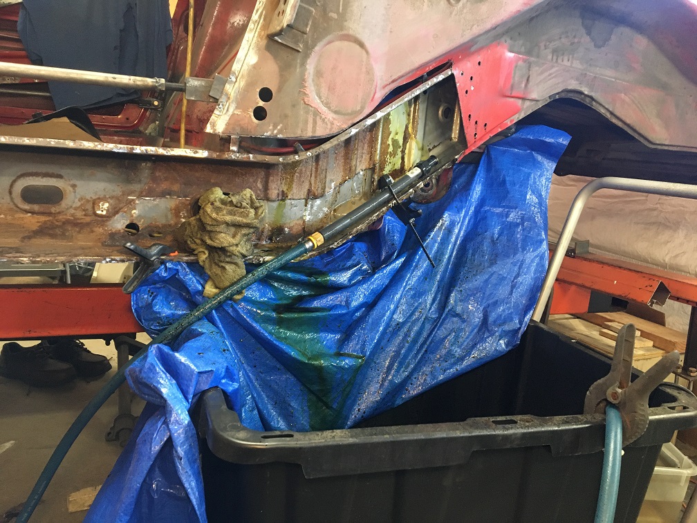 As you can see the upper portion of the long is now nice and gray, 50 year old metal renewed! Arrow is pointing at the fan spray pattern. 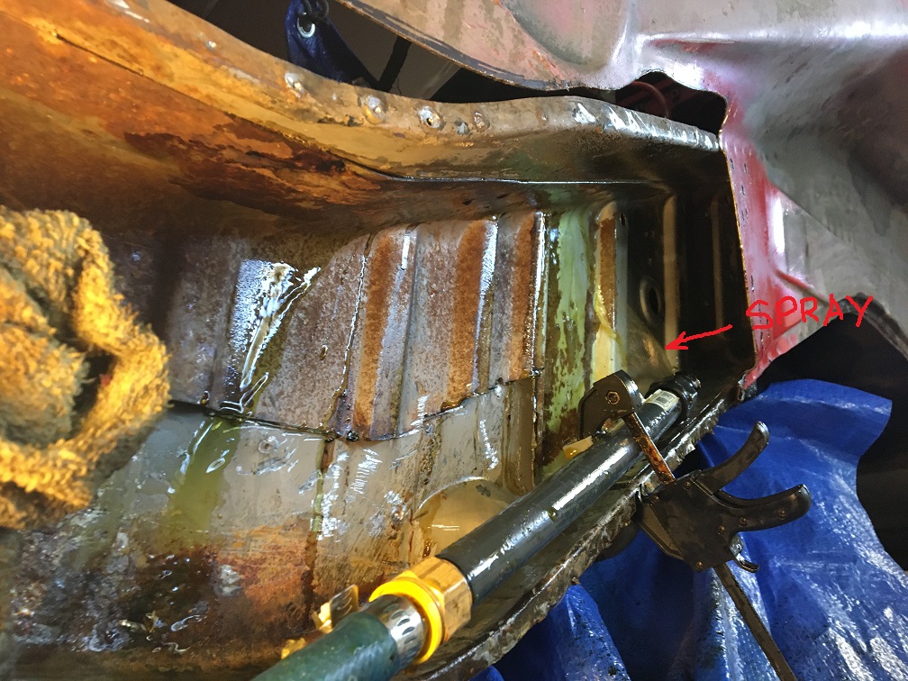 And a last one because this is so cool! (IMG:style_emoticons/default/biggrin.gif) 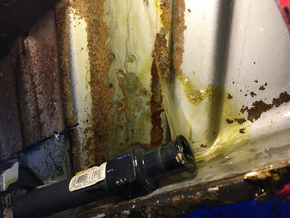 After a few days of progressively moving the spray head from top to bottom, I used another tote with a mix of water and baking soda and flushed the whole area for 1/2 day to neutralize the acid. @Mayne , Next, I plan on using some Eastwood rust encapsulation that I will brush inside. Then, after having closed back the long, I will use the Eastwood inner chassis spray with the flexible hose and nozzle, or spray cavity wax. With all of this done, we can now see what was hiding below these bumps (tip of the iceberg) I had noticed a while back. Here is the refresher picture of these bumps: 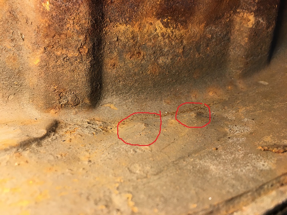 And here is what was under that bumpy inner layer... (IMG:style_emoticons/default/rolleyes.gif) 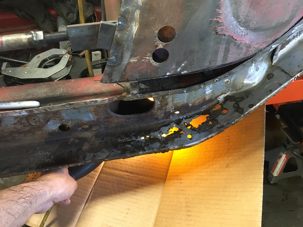 So I now know what will need to be cut out of the lower part of the inner long. Time to look at the donor parts I actually have to see what can be used. First step, dismantling the factory assembly by drilling every spot weld and separating every part... (IMG:style_emoticons/default/smash.gif) After splitting the outer from the inner of the donor parts a few weeks ago, here is what have. To assess if the metal both of the inside-inner and inside-outer can be used, I need to dismantle this whole assembly. So the engine mount needs to come off and the inside suspension console too. Hopefully I can achieve this while saving these parts. I don't think I will need them, but maybe someone here will. 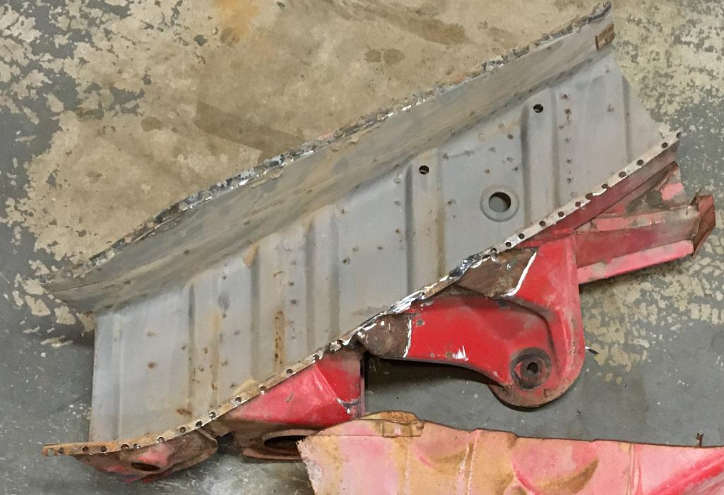 And here is the engine mount removed. There is some rust (IMG:style_emoticons/default/dry.gif) but it is too early to fully assess at this point. As you can see the separation work of the inner suspension console is well on its way. 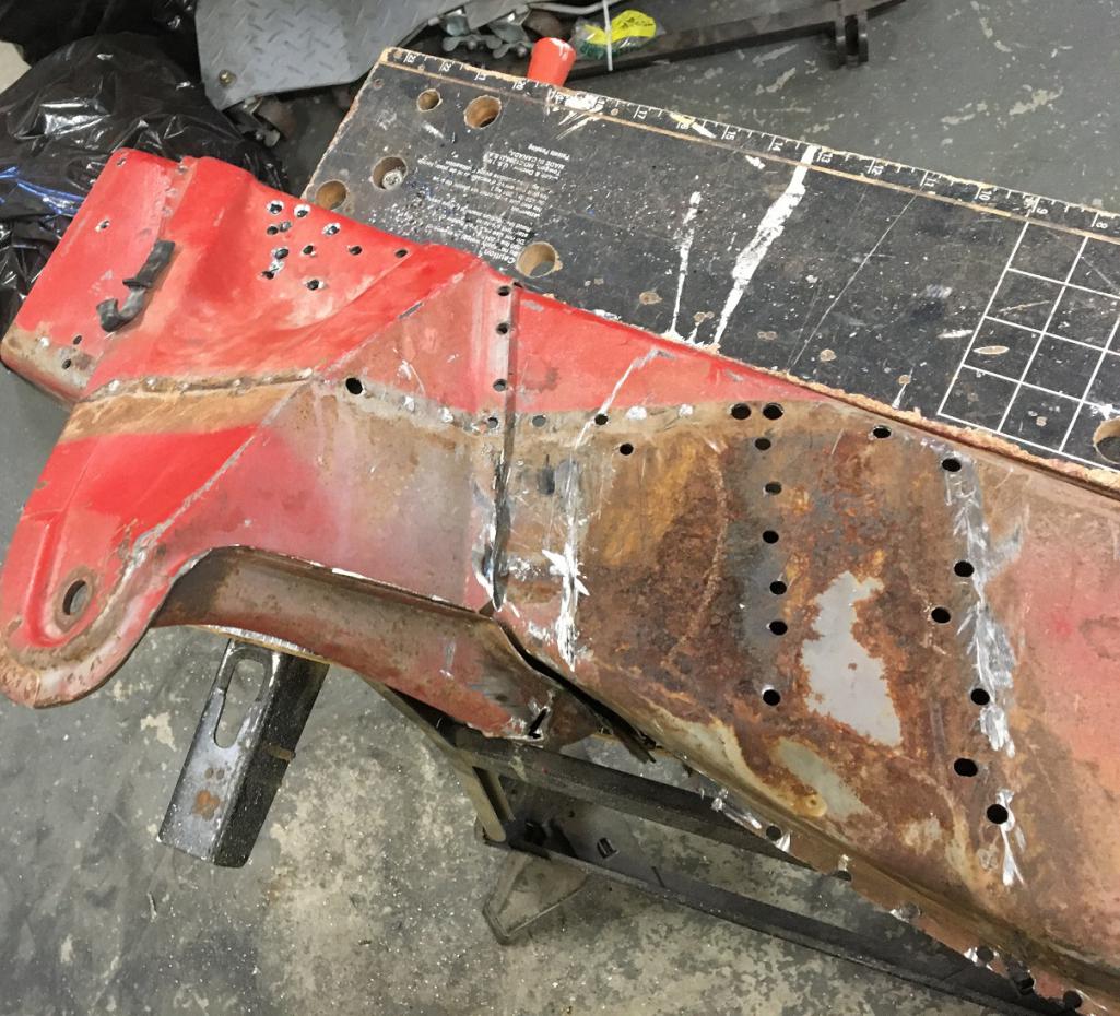 And here is the inner long free of all attached components. I am interested in this portion circled in red. 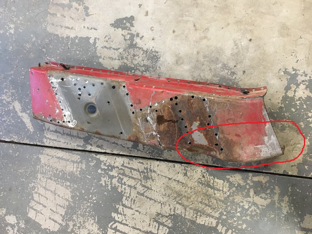 That being said, I am actually interested in both the outside-inner (seen here ^^^) and the inside-inner (seen below). So I will need to separate the two onion layers... Here we can see what I am looking at using. Fingers crossed for the metal to be in good shape at the interface. As we can see I have stated to separate the two layers. 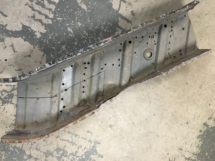 More to come, stay tuned! (IMG:style_emoticons/default/smash.gif) |
| Alain V. |
 Jul 13 2023, 06:07 PM Jul 13 2023, 06:07 PM
Post
#133
|
|
Member   Group: Members Posts: 161 Joined: 15-March 13 From: Kansas Member No.: 15,655 Region Association: None 
|
Something really satisfying about dissolving rust and finding clean metal. Looks like you are making good progress.
|
| 930cabman |
 Jul 14 2023, 07:37 AM Jul 14 2023, 07:37 AM
Post
#134
|
|
Advanced Member     Group: Members Posts: 3,695 Joined: 12-November 20 From: Buffalo Member No.: 24,877 Region Association: North East States 
|
Very cool process (IMG:style_emoticons/default/beerchug.gif) (IMG:style_emoticons/default/beerchug.gif)
|
| Montreal914 |
 Aug 6 2023, 11:55 AM Aug 6 2023, 11:55 AM
Post
#135
|
|
Senior Member    Group: Members Posts: 1,700 Joined: 8-August 10 From: Claremont, CA Member No.: 12,023 Region Association: Southern California 
|
Some progress to share:
Before continuing the previous post with the preparation of the repair piece for the outside-inner lower elbow area, I went on and actually cut out the bad metal, to really establish the repair piece I will need. Here is the situation: The black sharpie line (circled in red) is where I have decided to cut and remove material. 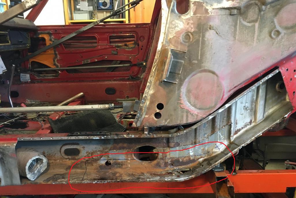 There are a few things to consider when removing this piece. First the floor is spot welded on the underside of it, then the two vertical walls of the firewall are flanged basically on either side of the oval port. Then, at the right end, I am actually cutting half way into where the engine mount is attached (embossment). I chose this location for a couple of reasons; 1- I wanted to see the engine mount metal behind it, 2- The engine mount will serve as overlapping layer. Based on what I have seen in removing the engine mount on my donor part, there is actually a gap between the engine mount and the embossment in the Outside-inner long metal. The plan is to add a metal layer to do an overlap on that joint. Plus the engine mount itself is an overlap. To preserve the various metal joining to the metal I am removing, I will be cutting and grinding it away, keeping the flanges intact and ready to receive the repair piece. Here is the beginning of the process on the left side: 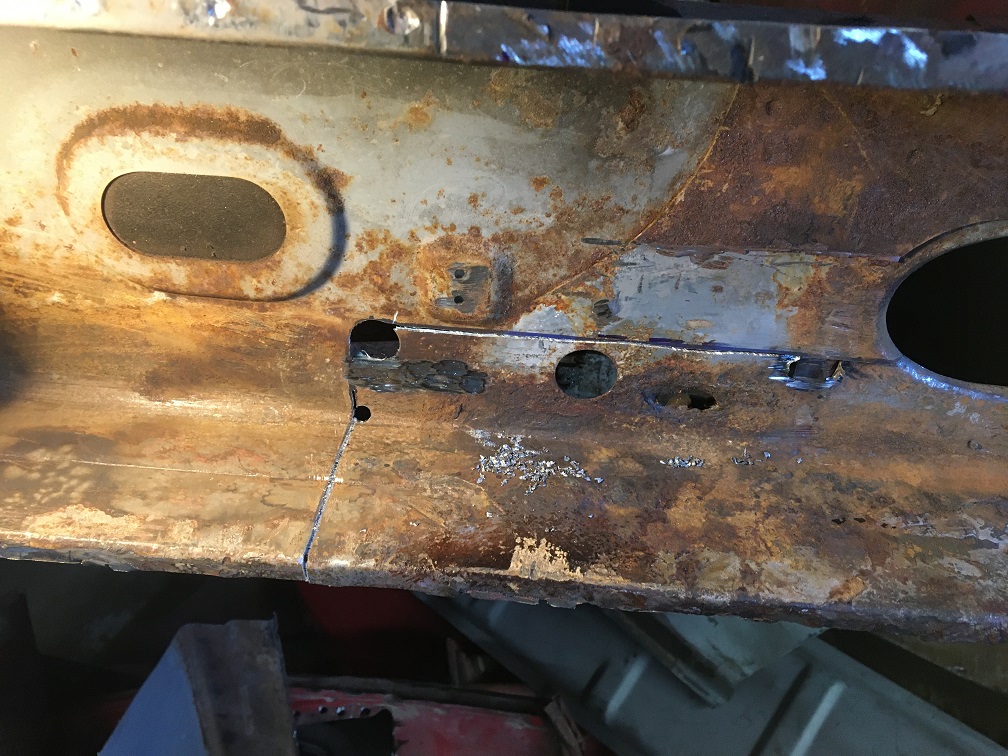 And here is that metal removed: 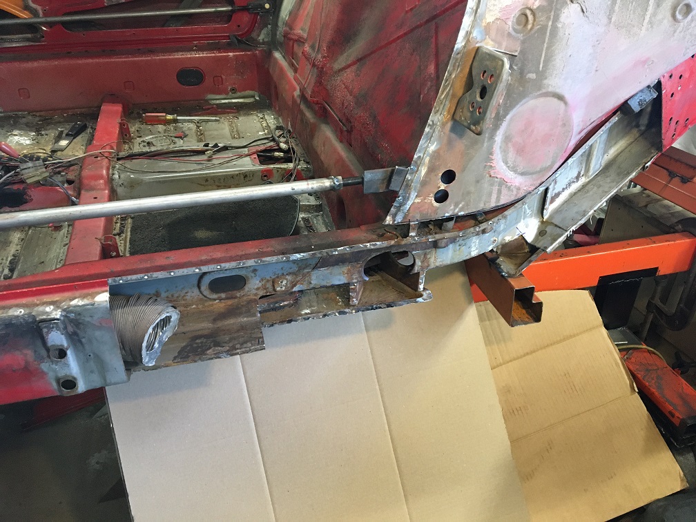 Closer view where we can see the two firewall flanges, the lower half of the engine mount (right end), obviously the floor, and the flange of the e-brake cable guide in the cabin. All of these flanges are nice and solid and will be the welding surface as I plug weld the repair piece in (minimizing upside down welds). 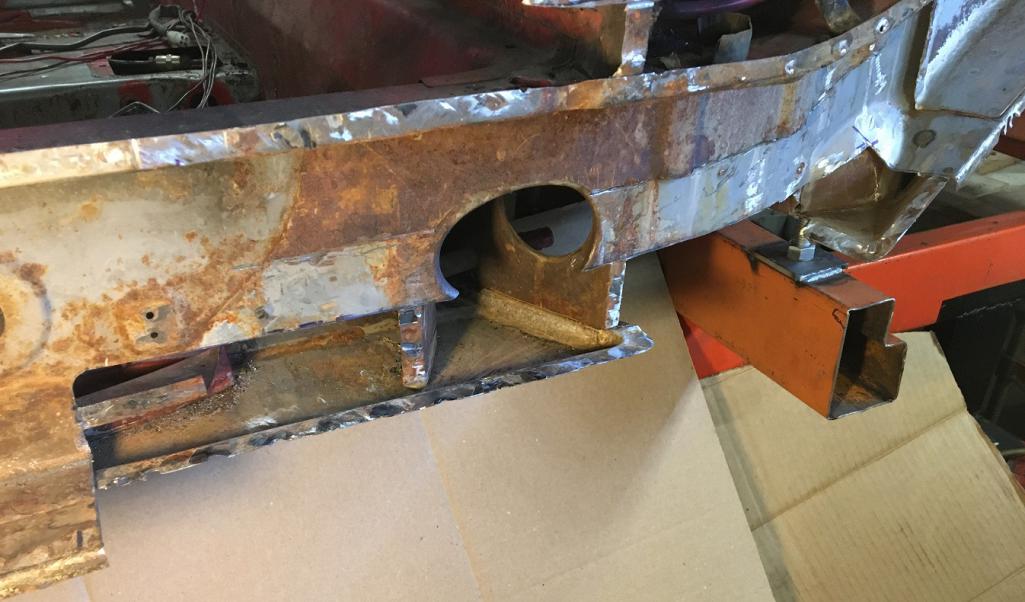 Now, time to prepare the repair piece. (IMG:style_emoticons/default/smash.gif) As show, in the last post, I need to dismantle the various sections of repair parts I have, assess their condition, and make a repair piece. The donor long I got was cut to the right of the jack post, basically behind the firewall. Therefore, the repair piece will have a vertical weld roughly in the middle. Here is the rear half of the doubled layered repair piece: 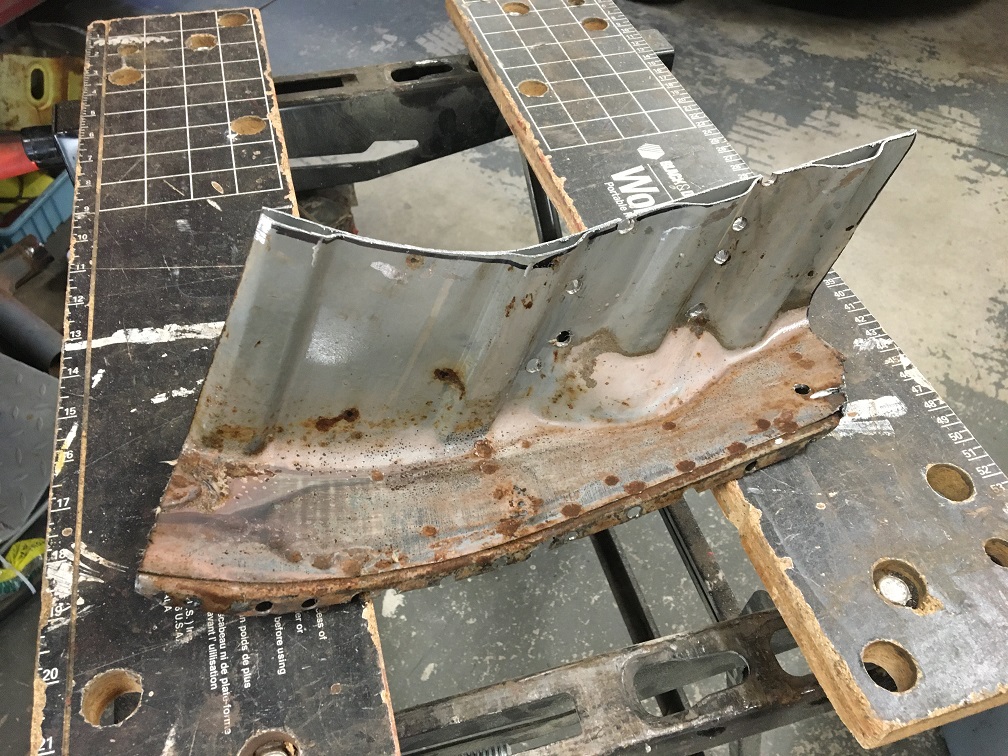 Since I will need both inner and outer layers, I had to drill all the spot welds to separate them. This works well, but unfortunately leaves one of the two pieces look like swiss cheese. (IMG:style_emoticons/default/dry.gif) We'll look into that later. 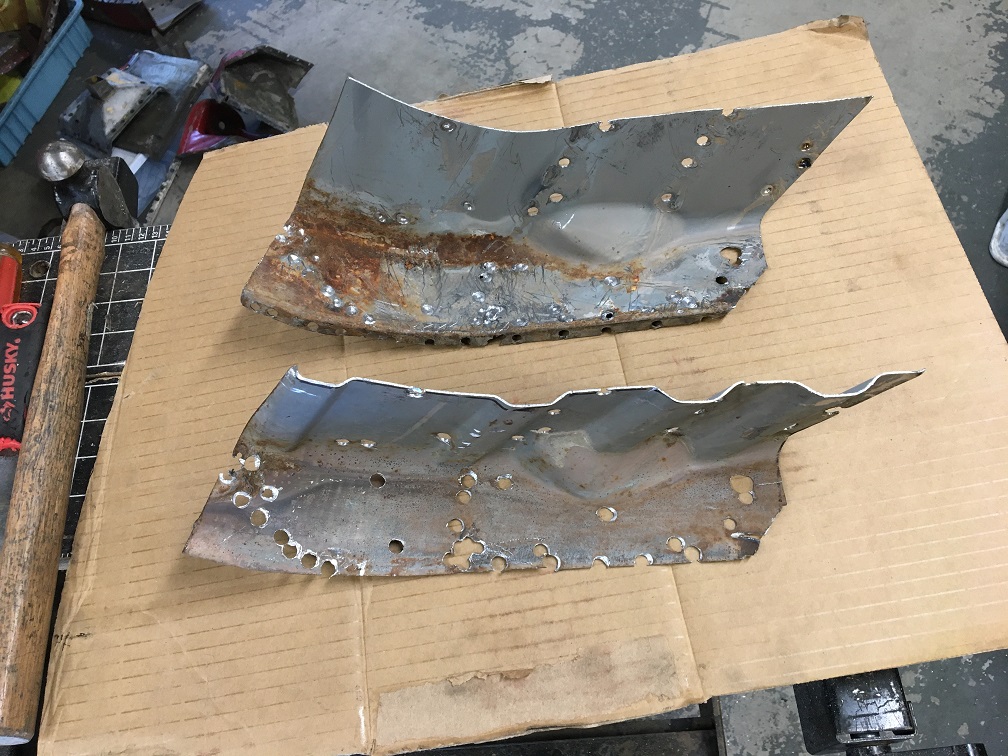 Overall, these two parts are pretty rust free and I am confident can be used as-is after getting de-rusted in citric acid. (IMG:style_emoticons/default/smile.gif) Now looking at the front half donor parts, same process; drill the spot weld to separate the two layers. 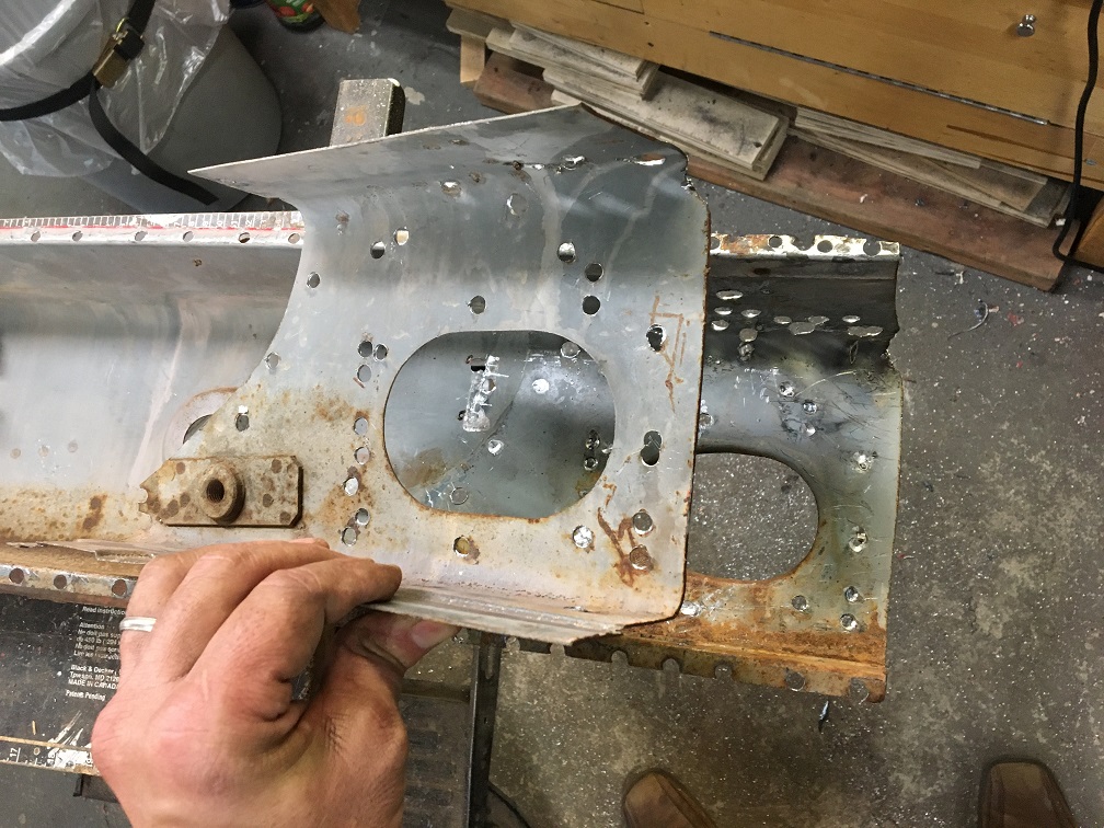 Unfortunately, these are not as good as the rear half's. Let's see what de-rusting will reveal... 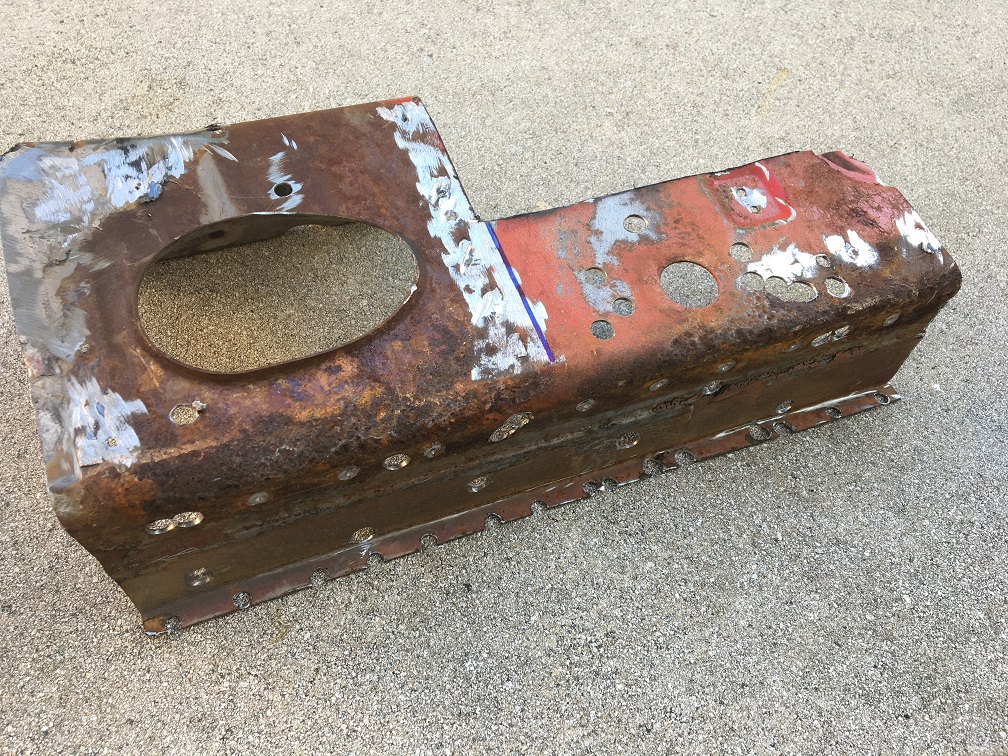 After a couple of days soaking in citric acid, here is the result. The rear end of it is a little pitted but not major, The front end (with the hole for the safety belt) is compromised in the fold and will need to be addressed (circled in red). (IMG:style_emoticons/default/dry.gif) 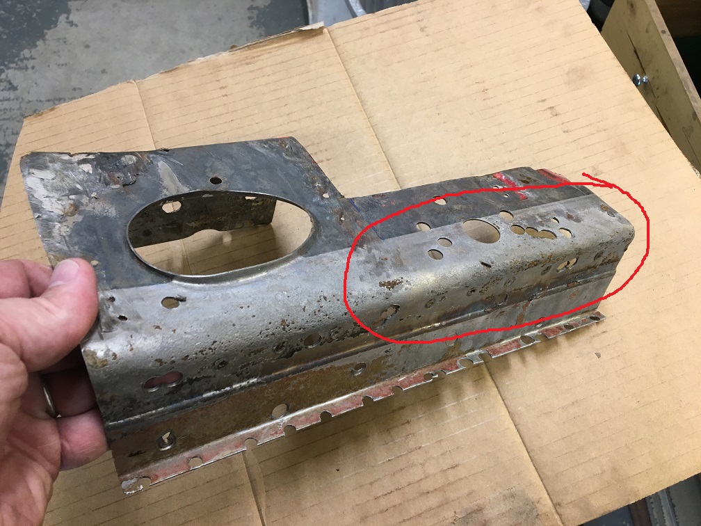 Most of the rest of the donor long is heavily pitted in the bottom fold except a section that I was able to cut out of. I will use this section below (black sharpie) for the repair piece. What I am after is having the step detail of the lower part where the floor attaches to the long (red arrow). 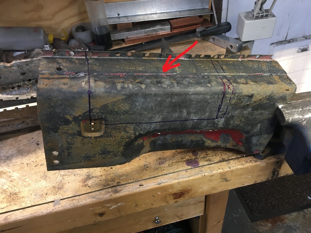 So here is the plan; joining the retrieved good part on the right to the left half with the oval hole. Not only will this replace the heavily pitted metal, it will also take care of a lot of swiss cheese. The hole for the seatbelt will be done before joining the two. 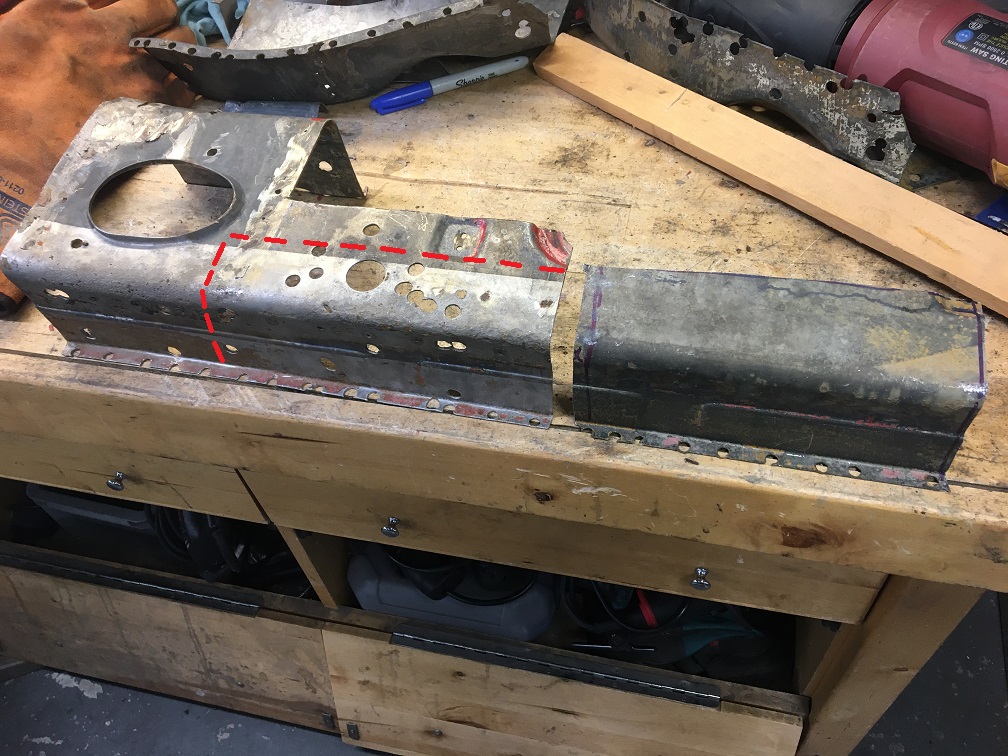 To be continued in next post... |
| Montreal914 |
 Aug 6 2023, 02:41 PM Aug 6 2023, 02:41 PM
Post
#136
|
|
Senior Member    Group: Members Posts: 1,700 Joined: 8-August 10 From: Claremont, CA Member No.: 12,023 Region Association: Southern California 
|
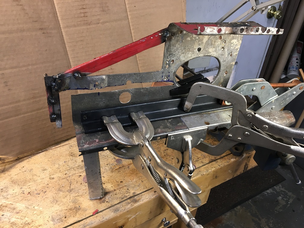
After carefully trimming both piece, I set them in this contraption (IMG:style_emoticons/default/wacko.gif) to join them straight. Hole for the seat belt in there now.
 And the back side. Notice the copper plate to absorb the heat. A similar plate lies under the bottom surface too. 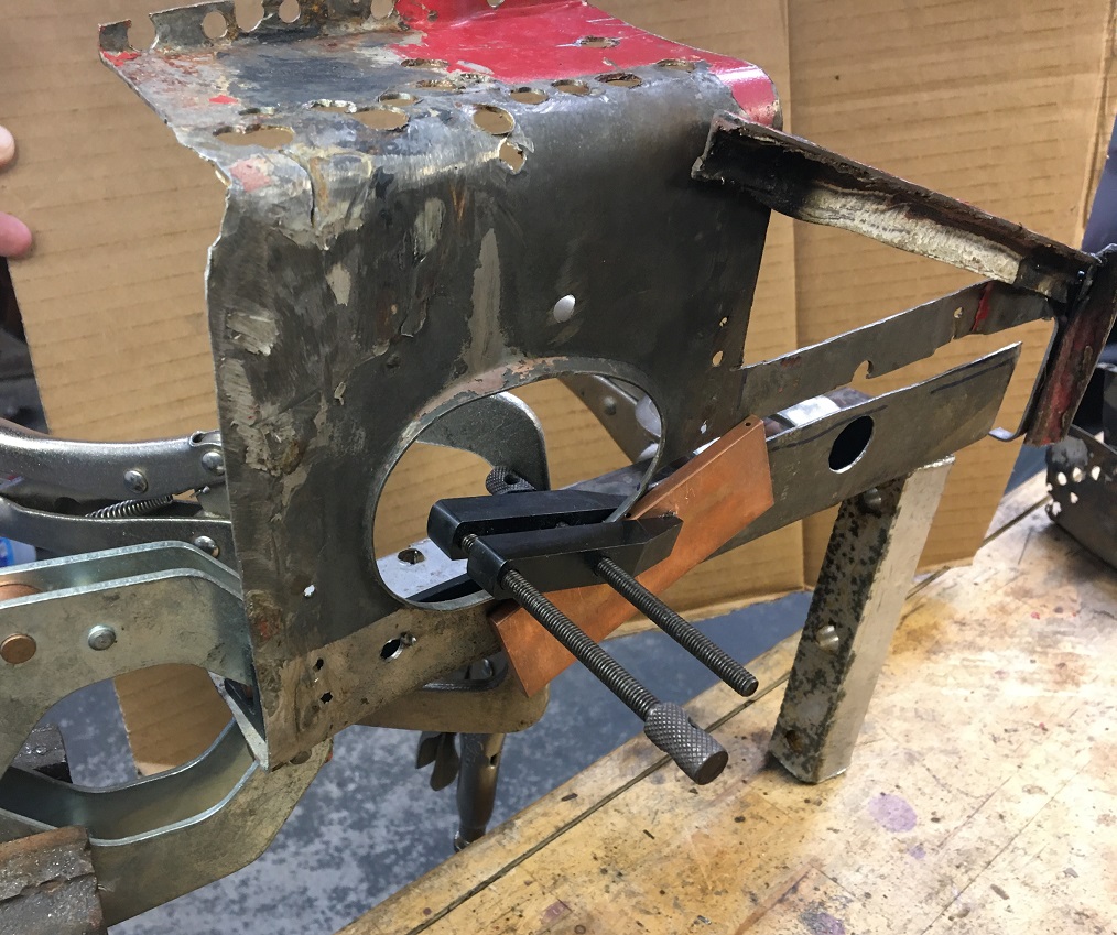 Now the two pieces are one. We can see some of the pitting on the right piece, not ideal, but not too bad. I may try to reinforce this. Here i am plugging some of the holes created by the spot weld drilling. 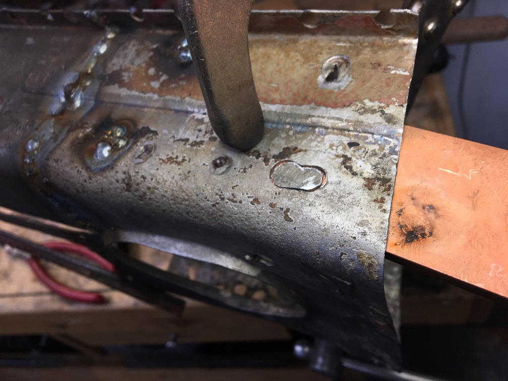 Moving on to attaching the rear section of the repair piece. Making progress! (IMG:style_emoticons/default/smile.gif) 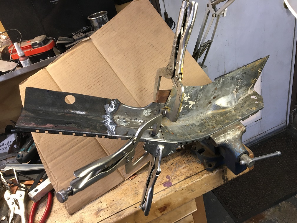 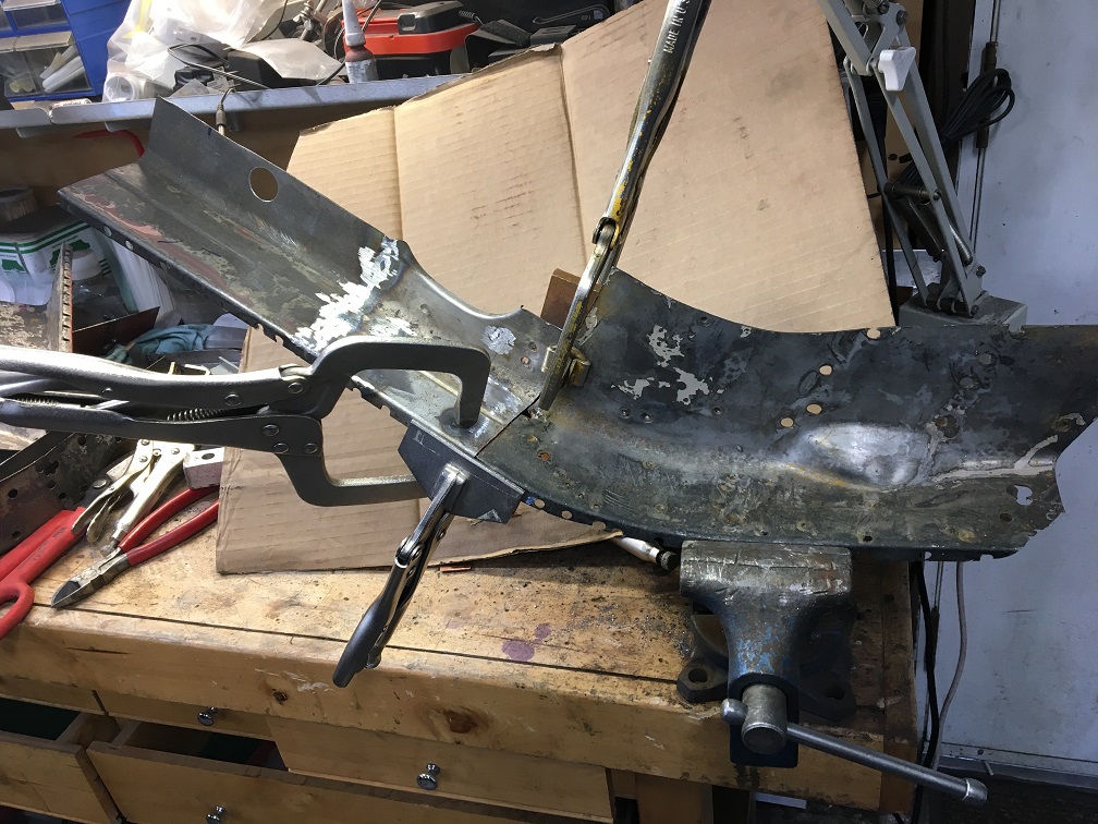 Finally, three becomes one! 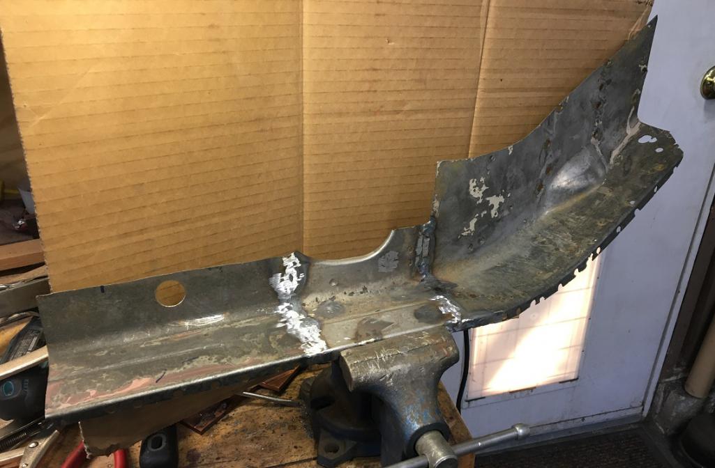 And after a lot of back and forth trimming, the part is now 95% ready to be installed. 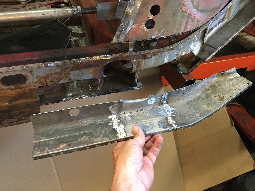 Fit is almost perfect, just a little bit of fine tuning and it will be ready. (IMG:style_emoticons/default/smile.gif) 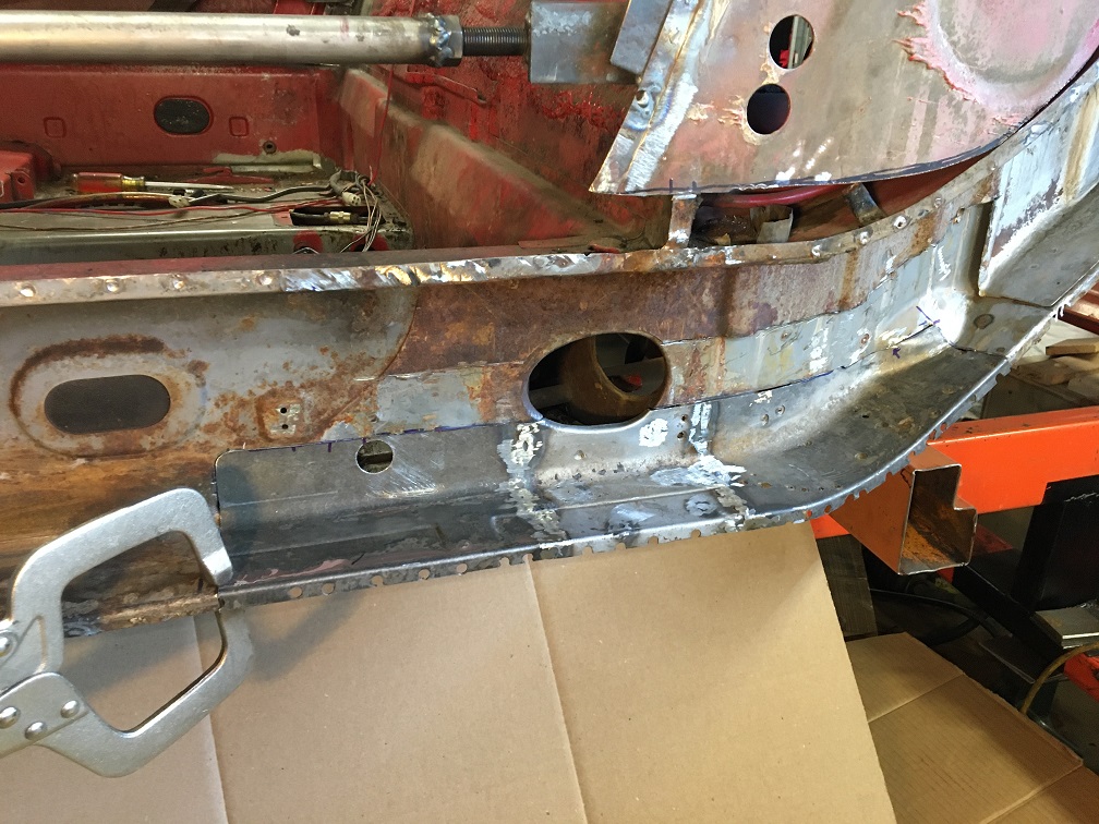 More to come soon! |
| nivekdodge |
 Aug 9 2023, 08:31 PM Aug 9 2023, 08:31 PM
Post
#137
|
|
Member   Group: Members Posts: 273 Joined: 28-August 21 From: Pittsburgh Pa Member No.: 25,860 Region Association: MidAtlantic Region 
|
You are kickin a and taking names!!!!!
|
| tygaboy |
 Aug 9 2023, 10:08 PM Aug 9 2023, 10:08 PM
Post
#138
|
|
914 Guru      Group: Members Posts: 5,451 Joined: 6-October 15 From: Petaluma, CA Member No.: 19,241 Region Association: Northern California 
|
Super nice job you're doing. Great fit-up on those panels. (IMG:style_emoticons/default/wub.gif) (IMG:style_emoticons/default/pray.gif)
|
| 930cabman |
 Aug 10 2023, 12:09 PM Aug 10 2023, 12:09 PM
Post
#139
|
|
Advanced Member     Group: Members Posts: 3,695 Joined: 12-November 20 From: Buffalo Member No.: 24,877 Region Association: North East States 
|
Prior to welding new sections in place, have you been double checking the alignment of your pickup points? Looking at your jig, it appears somewhat light gauge. A quick double check will let you know all is good before new metal is secured in place.
You don't have to ask why ........... |
| Montreal914 |
 Aug 10 2023, 01:31 PM Aug 10 2023, 01:31 PM
Post
#140
|
|
Senior Member    Group: Members Posts: 1,700 Joined: 8-August 10 From: Claremont, CA Member No.: 12,023 Region Association: Southern California 
|
Prior to welding new sections in place, have you been double checking the alignment of your pickup points? Looking at your jig, it appears somewhat light gauge. A quick double check will let you know all is good before new metal is secured in place. You don't have to ask why ........... Although it looks like I am ready to weld this in, I am not there yet. Yes I will measure everything and also temporarily reinstall the fender to check door gap. Each little step is at slow pace where subsequent steps planning are part of every move. Think think think, act, trying to minimize the “ah darn” moments. |
  |
15 User(s) are reading this topic (15 Guests and 0 Anonymous Users)
0 Members:

|
Lo-Fi Version | Time is now: 22nd November 2024 - 09:26 PM |
Invision Power Board
v9.1.4 © 2024 IPS, Inc.


