|
|

|
Porsche, and the Porsche crest are registered trademarks of Dr. Ing. h.c. F. Porsche AG.
This site is not affiliated with Porsche in any way. Its only purpose is to provide an online forum for car enthusiasts. All other trademarks are property of their respective owners. |
|
|
  |
| 914Sixer |
 Jul 11 2021, 06:20 AM Jul 11 2021, 06:20 AM
Post
#21
|
|
914 Guru      Group: Members Posts: 9,034 Joined: 17-January 05 From: San Angelo Texas Member No.: 3,457 Region Association: Southwest Region 
|
Took me a minute because the harness is missing plug but it a a heated back window harness.
|
| GeorgeKopf |
 Jul 11 2021, 09:27 AM Jul 11 2021, 09:27 AM
Post
#22
|
|
Member   Group: Members Posts: 189 Joined: 9-February 21 From: Princeton, NJ Member No.: 25,186 Region Association: MidAtlantic Region |
Thank you Ian!
I'm having a bit of trouble reading the wiring diagram. 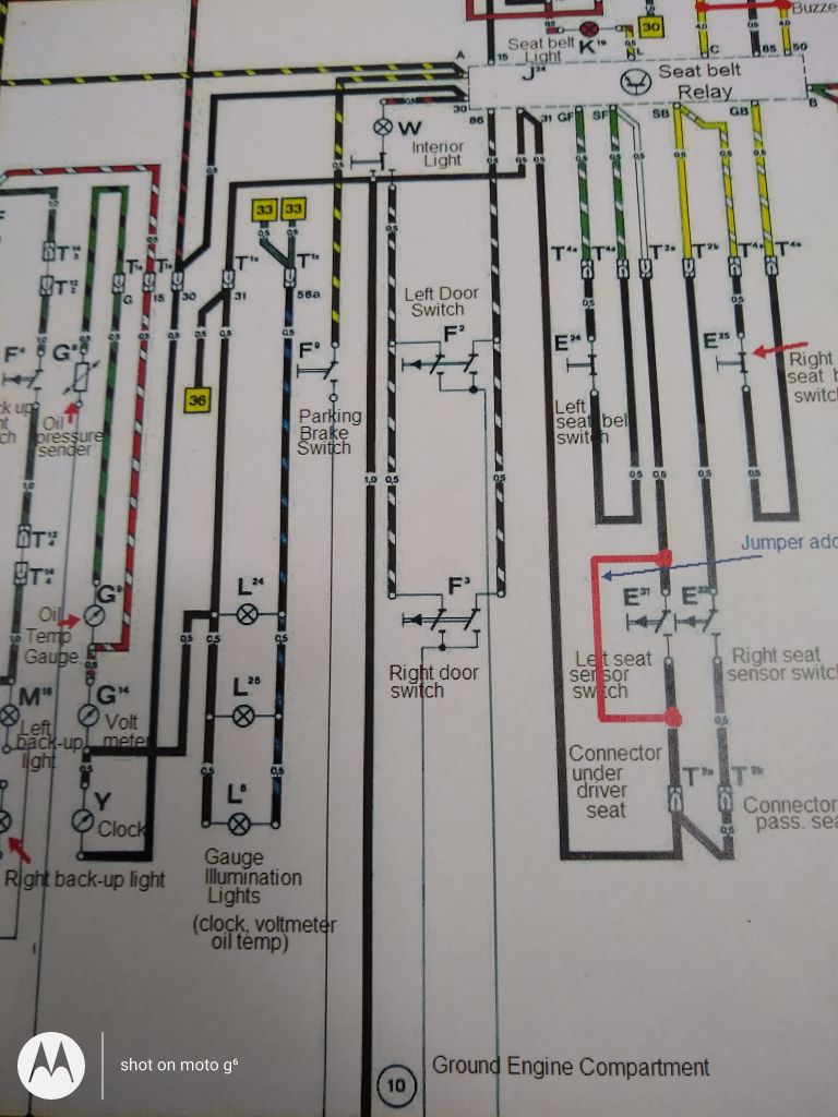 The wiring diagram has: the door switches as brown/white (both wires to both switches?) If both wires go to both switches, in parallel, won't both doors have to be open to break the circuit? the parking brake as brown/yellow the interior light as black/red Do the door switches ground through the chassis? Does the parking brake switch ground through the chassis? Thanks. George |
| GeorgeKopf |
 Jul 11 2021, 09:30 AM Jul 11 2021, 09:30 AM
Post
#23
|
|
Member   Group: Members Posts: 189 Joined: 9-February 21 From: Princeton, NJ Member No.: 25,186 Region Association: MidAtlantic Region |
Thank you Mark.
I'm fairly sure that my rear window doesn't have any wires hanging off of it. (It is wrapped up and in storage right now.) I also don't have a switch to turn it on. I'm guessing that I don't need to install that harness. Thanks. George |
| iankarr |
 Jul 11 2021, 04:43 PM Jul 11 2021, 04:43 PM
Post
#24
|
|
The wrencher formerly known as Cuddy_K     Group: Members Posts: 2,526 Joined: 22-May 15 From: Heber City, UT Member No.: 18,749 Region Association: Intermountain Region 
|
@GeorgeKopf the wiring on my 73 harness doesn't follow that color scheme. Or the colors have faded. With regard to the door switches, I'm not sure exactly how the circuit works, but I know there are 4 connections on each switch. Looks like your diagram only has two, so it may not be for a 73. Recommend picking up a diagram from prosperos garage - http://www.colorwiringdiagrams.com. They seem easier to read. At least for me!
|
| ejm |
 Jul 12 2021, 08:52 AM Jul 12 2021, 08:52 AM
Post
#25
|
|
I can see the light at the end of the tunnel     Group: Members Posts: 2,705 Joined: 3-February 03 From: Massachusetts Member No.: 224 Region Association: None |
QUOTE If both wires go to both switches, in parallel, won't both doors have to be open to break the circuit? When a door is open the switch closes completing the circuit to ground QUOTE Do the door switches ground through the chassis? From '74 on they ground thru the switch body QUOTE I'm not sure exactly how the circuit works, but I know there are 4 connections on each switch. Looks like your diagram only has two, so it may not be for a 73. Correct, thru the '73 model year the switch had 4 contacts and grounded thru a wire. QUOTE Does the parking brake switch ground through the chassis? Yes on all years @GeorgeKopf @iankarr |
| GeorgeKopf |
 Jul 12 2021, 10:58 AM Jul 12 2021, 10:58 AM
Post
#26
|
|
Member   Group: Members Posts: 189 Joined: 9-February 21 From: Princeton, NJ Member No.: 25,186 Region Association: MidAtlantic Region |
Thank you Ed.
It occurs to me that using just the two pole switches should work just fine. Grounding through the chassis or the brown wires should be identical. Thanks. George |
| GeorgeKopf |
 Jul 13 2021, 01:05 PM Jul 13 2021, 01:05 PM
Post
#27
|
|
Member   Group: Members Posts: 189 Joined: 9-February 21 From: Princeton, NJ Member No.: 25,186 Region Association: MidAtlantic Region |
I've traversed the entire harness and am now deep into the dash components. It looks like at some time the wire from the light switch to the parking light indicator completely melted. The sheathing is stuck to multiple wires and there are brown marks everywhere.
Any idea what could have caused that melt down? I'm wondering if the wire rubbed through the light holder and grounded to the gauge. If so, I'm thinking of replacing all of the little bulb holders with ones that have an attached male flat connector. (Instead of the kind where the wire goes through the end of the bulb holder.) Editors note: I was reading the 1973 fuse box wiring diagram and found this gem. "High Beam indicator (Tach) and parking light indicator (Speedo) are unfused…" So that explains that. (IMG:style_emoticons/default/idea.gif) Thanks. George |
| 914werke |
 Jul 13 2021, 04:20 PM Jul 13 2021, 04:20 PM
Post
#28
|
|
"I got blisters on me fingers"           Group: Members Posts: 11,030 Joined: 22-March 03 From: USofA Member No.: 453 Region Association: Pacific Northwest 
|
What is this harness for? It was in the box of electrical parts. I have no idea what year it is from. George That is the accessory harness to control the optional defrost R. glass. Its missing the relay board connector (hard to find) (IMG:style_emoticons/default/smile.gif) It normally threads through the snorkle at the firewall, yours has been removed. |
| GeorgeKopf |
 Jul 13 2021, 10:50 PM Jul 13 2021, 10:50 PM
Post
#29
|
|
Member   Group: Members Posts: 189 Joined: 9-February 21 From: Princeton, NJ Member No.: 25,186 Region Association: MidAtlantic Region |
Thanks Rich.
Now I'm working through the gauges and I think I've got it figured out. My combo gauge looks like this: 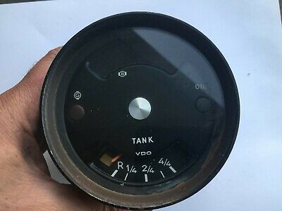 Gauge wiring for 1973 Porsche 914. 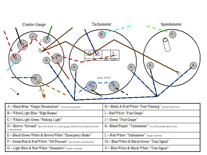 Here are some pictures of the tangled mess of wires. I left off the gauge illumination (blue/black) because it was cluttering the pictures. Combo Gauge 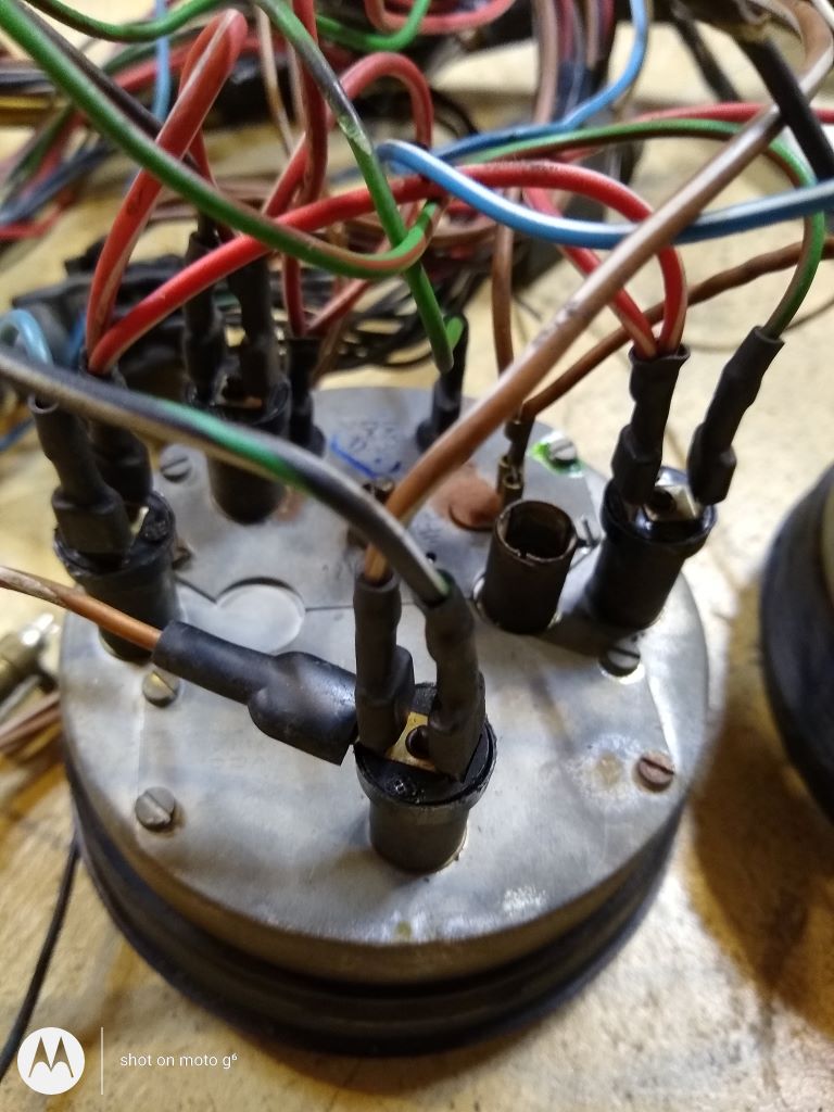 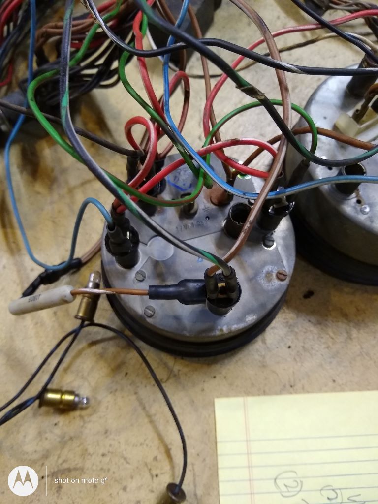 Tachometer 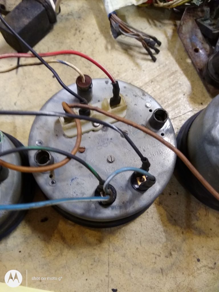 Speedometer 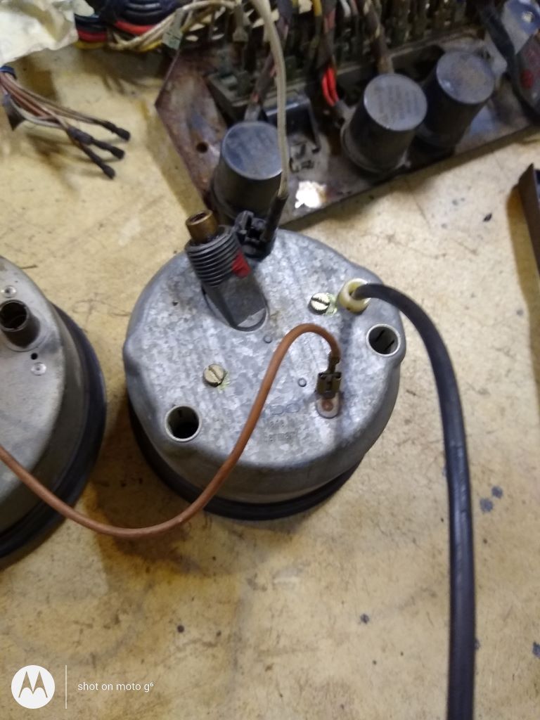 Please let me know if I've got this wrong!!! If so, I'll update the drawing for posterities sake. |
  |
1 User(s) are reading this topic (1 Guests and 0 Anonymous Users)
0 Members:

|
Lo-Fi Version | Time is now: 27th December 2024 - 12:15 PM |
Invision Power Board
v9.1.4 © 2024 IPS, Inc.


