|
|
|
Porsche, and the Porsche crest are registered trademarks of Dr. Ing. h.c. F. Porsche AG.
This site is not affiliated with Porsche in any way. Its only purpose is to provide an online forum for car enthusiasts. All other trademarks are property of their respective owners. |
|
|

  |

| Villemi |
 Dec 25 2021, 09:21 AM Dec 25 2021, 09:21 AM
Post
#1
|
|
Newbie  Group: Members Posts: 48 Joined: 7-January 20 From: France Member No.: 23,807 Region Association: France |
Hello,
We know on our D -Jetronic harness some male connectors 2,3,4,5 ways with female connectors with female pins inside. (IMG:http://www.914world.com/bbs2/uploads_offsite/i48.servimg.com-23807-1640445696.1.jpg) Do you know female connectors with male pins inside. ? I need your help because I want to use on my 914 Porsche a 123 ignition distributor. For the OEM distributor I have a 3 ways female connector and for the harness 3ways male connector I'd like to make a little harness with a 3 ways male on one side and 3 ways female connector on the other side It's easy to find male connectors with female pins but I don't find female connector with male pins. Do you know where I can find these parts ? The advantage of this little harness is if I have problems with the 123 ignition distributor I can use my OEM one without harness modification. Can you help me please ? PS: what is the item number of these D-Jetronic connectors ? Best regards Michel |
   |

 
|
| JeffBowlsby |
Dec 25 2021, 10:06 AM
Post
#2
|
|
914 Wiring Harnesses Group: Members Posts: 8,704 Joined: 7-January 03 From: San Ramon CA Member No.: 104 Region Association: None |
I have never seen these or used them but I think they would work.
AMP 928931-1 But this does not solve other issues for our weather exposed engine bays. |
 |
|
| JeffBowlsby |
Dec 25 2021, 11:23 AM
Post
#3
|
|
914 Wiring Harnesses Group: Members Posts: 8,704 Joined: 7-January 03 From: San Ramon CA Member No.: 104 Region Association: None |
A concern with using the 123 dizzy with DJet (which I support) is this connection at the ‘trigger points’. The stock trigger points configuration is a male connector housing on the harness into a female housing on the trigger points on the dizzy. The rubber boot provides critical functions - it covers the connection holding the housings together, waterproofing/dirtproofing the connection, protecting the exposed wires from heat degradation and providing strain relief to the wires.
123 provides the two wires needed emanating out of the dizzy body, but does not address the functional electrical connectivity concerns. It’s easy enough to install heat shrink tubing over the exposed wires but how about the connection to the harness? I think it needs either a custom molded make terminal connection just like the factory mounted to the dizzy, or at least a new 2 piece connector housing (male/female), with mating quick disconnect terminals and some way to waterproof/dirt proof the connection. For the second option it would be good if the terminals on the existing FI harness could simply be re-inserted into the new housing without needed to cut or modify the factory FI harness. |
|
|
|
| Villemi |
Dec 25 2021, 03:31 PM
Post
#4
|
|
Newbie Group: Members Posts: 48 Joined: 7-January 20 From: France Member No.: 23,807 Region Association: France |
I began a 3D prototype drawing this evening
(IMG:http://www.914world.com/bbs2/uploads_offsite/i48.servimg.com-23807-1640467863.1.jpg) I continue tomorrow I need some male pins items that I could put in the connector please |
|
|
|
| adolimpio |
Dec 27 2021, 08:36 PM
Post
#5
|
|
Art Group: Members Posts: 182 Joined: 10-March 10 From: Greenwood SC Member No.: 11,449 Region Association: South East States |
|
|
|
|
| FlacaProductions |
Jun 17 2024, 04:14 PM
Post
#6
|
|
Senior Member Group: Members Posts: 1,775 Joined: 24-November 17 From: LA Member No.: 21,628 Region Association: Southern California |
Necro-thread revival alert!
I've been thinking about this a bit - anyone have any ideas as to obtaining a 3-pin male connector so one could insert the 123 Distributor pins and get a good, solid long-term answer for the install? |
|
|
|
| windforfun |
Jun 17 2024, 06:41 PM
Post
#7
|
|
Senior Member Group: Members Posts: 1,961 Joined: 17-December 07 From: Blackhawk, CA Member No.: 8,476 Region Association: None |
"Necro-thread revival alert!"
Is this a bad thing? Be alert, we need more lerts. (IMG:style_emoticons/default/av-943.gif) (IMG:style_emoticons/default/av-943.gif) (IMG:style_emoticons/default/av-943.gif) |
|
|
|
| GregAmy |
Jun 18 2024, 06:40 AM
Post
#8
|
|
Advanced Member Group: Members Posts: 2,388 Joined: 22-February 13 From: Middletown CT Member No.: 15,565 Region Association: North East States |
Why not convert it to a crimp-on Deutsch-type connector? When I built the wiring harness for my Microsquirt conversion (see sig), I used these on everything:
https://www.amazon.com/gp/product/B07L9XNFGG Those are available in much larger quantities (for example, there's a 152-piece set). I much prefer the true Deutsch barrel connectors but these are much more affordable, and they require standard hand wiring tools, |
|
|
|
| FlacaProductions |
Jun 18 2024, 09:04 AM
Post
#9
|
|
Senior Member Group: Members Posts: 1,775 Joined: 24-November 17 From: LA Member No.: 21,628 Region Association: Southern California |
@GregAmy - that can always be done, sure - but I'm trying to not cut factory wiring. Not really sure why since I know I'm not going back. This isn't a concours car - heck, it was originally a 1.8 so it's not even the original engine.
Maybe you're right. |
|
|
|
| JeffBowlsby |
Jun 18 2024, 09:12 AM
Post
#10
|
|
914 Wiring Harnesses Group: Members Posts: 8,704 Joined: 7-January 03 From: San Ramon CA Member No.: 104 Region Association: None |
While these connectors have some good features, me no likey them for a weather-exposed, hot engine bay environment.
Heat and fluid contamination kills exposed wiring. A short section of the wires are exposed where they enter the connector housing and heat shrink on the harness, and each entering wire has no stress relief at the entry point. Its a vulnerable condition susceptible to wiring degradation. |
|
|
|
| Superhawk996 |
Jun 18 2024, 01:09 PM
Post
#11
|
|
914 Guru Group: Members Posts: 6,502 Joined: 25-August 18 From: Woods of N. Idaho Member No.: 22,428 Region Association: Galt's Gulch |
QUOTE(JeffBowlsby @ Jun 18 2024, 11:12 AM)  A short section of the wires are exposed where they enter the connector housing and heat shrink on the harness, and each entering wire has no stress relief at the entry point. Its a vulnerable condition susceptible to wiring degradation. Gotta disagree with this. Deutche connectors are 100% acceptable. This style of connector is widely used in automotive wiring by all OEM’s and has hundreds of milllions of miles proving out its durability and acceptability. I’m taking about all kinds of shaker table, laboratory, and real world on-road testing backed up by known warranty costs and field failure rates. The individual wires ARE strain relieved by the pins. There is a crimp to establish electrical contact. Behind that crimp is a second set of “wings” that roll around the wire insulation - acting as a strain relief to the electrical crimp and supports the wire as it exits the connector body. Trying to make an additional strain relief out of heat shrink causes nothing but endless trouble. The heat shrink “strain relief” then causes the pins to break or to be pulled on by the added weight of all the heat shrink on the wiring and results in pins being pulled out of the connector body at best or intermittent electrical connections which are the the worst since intermittent issues are terrible to troubleshoot. When I did DoD work, we could not get this through the heads of some that just don’t understand automotive wiring, or those that don’t appreciate how much development, testing, and validation have gone into modern automotive wiring over the past 50 years. The defense company I worked for actually lost that contract due to the multitude of issues the program had related to wiring. 100% of which were self created by people that thought they were doing the right thing by adding “strain relief” and refused to understand how these connectors are designed to function. (IMG:style_emoticons/default/headbang.gif) |
|
|
|
| Superhawk996 |
Jun 18 2024, 01:18 PM
Post
#12
|
|
914 Guru Group: Members Posts: 6,502 Joined: 25-August 18 From: Woods of N. Idaho Member No.: 22,428 Region Association: Galt's Gulch |
Strain relief for individual pin circled in green.
the other style of Deutche cannon plug connector pin shown on right. These style pins have no strain relief but will be supported by the connector and/or a strain relief boot as it exits the multi-wire body (usually 25+ wires). These style “mil-spec” connectors are stupid expensive and still are not without their own problems. 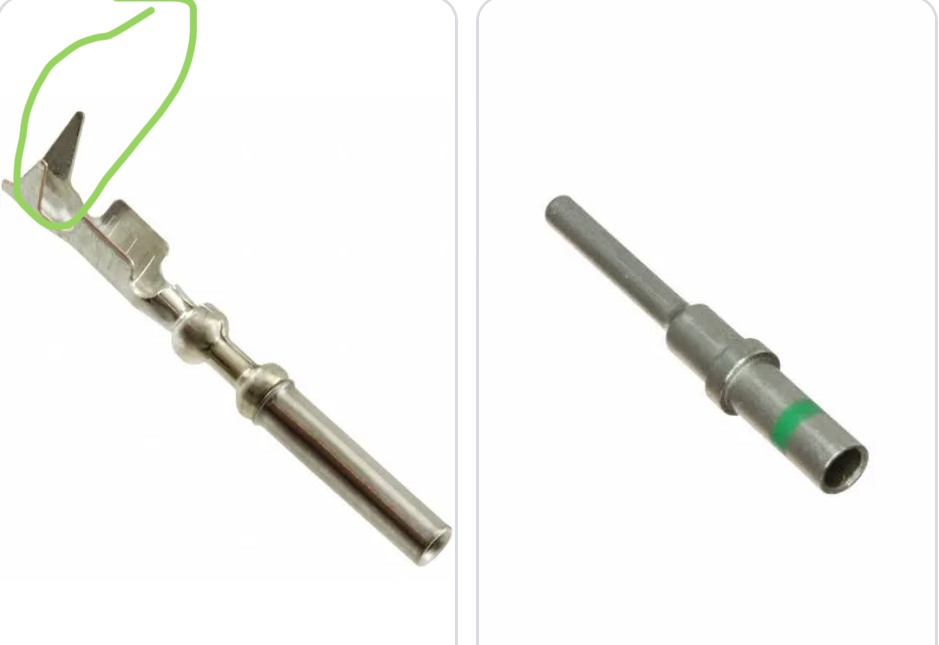 |
|
|
|
| Superhawk996 |
Jun 18 2024, 01:21 PM
Post
#13
|
|
914 Guru Group: Members Posts: 6,502 Joined: 25-August 18 From: Woods of N. Idaho Member No.: 22,428 Region Association: Galt's Gulch |
QUOTE(Villemi @ Dec 25 2021, 05:31 PM) I began a 3D prototype drawing this evening (IMG:http://www.914world.com/bbs2/uploads_offsite/i48.servimg.com-23807-1640467863.1.jpg) I continue tomorrow I need some male pins items that I could put in the connector please Having said all that about modern wiring, (IMG:style_emoticons/default/smilie_pokal.gif) to you for developing something to interface with our 50+ year old 914 wiring and ancient Molex style connections and simple spade terminals. |
|
|
|
| FlacaProductions |
Jun 18 2024, 01:51 PM
Post
#14
|
|
Senior Member Group: Members Posts: 1,775 Joined: 24-November 17 From: LA Member No.: 21,628 Region Association: Southern California |
Yeah - unfortunately, the OP on this thread hasn't logged in in 14 months...
|
|
|
|
| Superhawk996 |
Jun 18 2024, 02:02 PM
Post
#15
|
|
914 Guru Group: Members Posts: 6,502 Joined: 25-August 18 From: Woods of N. Idaho Member No.: 22,428 Region Association: Galt's Gulch |
QUOTE(FlacaProductions @ Jun 18 2024, 03:51 PM) Yeah - unfortunately, the OP on this thread hasn't logged in in 14 months... Doh - all the more reason to just go to a Deutche connector. |
|
|
|
| JeffBowlsby |
Jun 19 2024, 07:22 AM
Post
#16
|
|
914 Wiring Harnesses Group: Members Posts: 8,704 Joined: 7-January 03 From: San Ramon CA Member No.: 104 Region Association: None |
QUOTE(Superhawk996 @ Jun 18 2024, 12:09 PM) Gotta disagree with this. Deutche connectors are 100% acceptable. To clarify my concerns, * No strain relief. Understood the strain relief provision at the point of the wire to the wire terminal which is concealed within the housing, no issue. The location of concern is where the wire to the free-hanging connector enters the housing. The connector design provides no strain relief here as does the boot on the D-Jet and L-jet harnesses. Movement of the wires over time as they deflect relative to the housing creates a fulcrum and stress concentration and ultimately a failure. Its a weakness of this connector design for long term durability in my experience. * Exposed wires where the wires enter the housing. The housing design allows no provision to protect the short section of exposed wires from where the harness casing ends and where they enter the housing, from heat and fluid contamination in the engine bay as does the boot on the D-Jet and L-jet harnesses. Both of which will ultimately cause a failure in my experience. https://www.youtube.com/watch?v=GQs7EPzDOak These two failure modes are the majority of the engine bay wiring harness failures I see from examining thousands of older, worn out engine bay harnesses with presumably gazillions of billions of miles on them collectively (creative huh (IMG:style_emoticons/default/laugh.gif) ) This Deutche style of connector provides a good sealed connection (although its a complicated multipart connector), but its interface with the wiring on the harness is not resolved for long term serviceability in a weather-exposed engine bay environment. If you ask me, I think there need something like a silicone boot between the connector housing and the harness cable. Attached thumbnail(s) 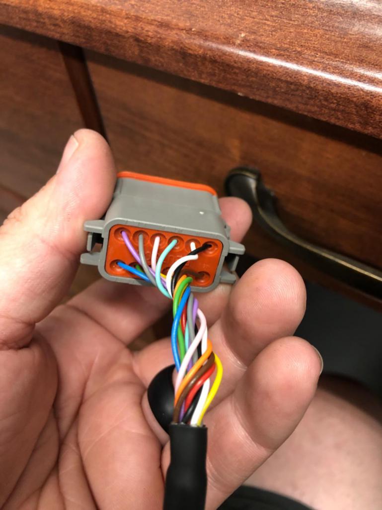
|
|
|
|
| Superhawk996 |
Jun 19 2024, 11:01 AM
Post
#17
|
|
914 Guru Group: Members Posts: 6,502 Joined: 25-August 18 From: Woods of N. Idaho Member No.: 22,428 Region Association: Galt's Gulch |
With all due respect, opinion doesn’t matter.
Thousands upon thousands of engineering man hours have been spent engineering wiring harness designs and automotive connectors to ensure high reliability. All the OEMs have their own laboratory facilities with vibration shaker tables and environmental test cells for proving out durability both at component and vehicle level. This isn’t guess work or opinion. Typical 4 post shaker used to validate at whole vehicle level in addition to on-road durability testing. https://www.youtube.com/watch?v=O0tPGOYFIfw?si=H2FBd_t7E8Z7Iok3 Likewise there are independent third parties that are continually doing competitive teardowns and engineering analysis on all OEM’s designs. If there are better engineering designs that result in higher durability, you can be sure those designs will be further evaluated by the OEM’s and then propagated. https://www.youtube.com/watch?v=-98gpXbcrXU?si=j7wIYpHljAjXLBZ9 I’m going to post some under hood photos from four different OEMs varying across 20 years of production and with one vehicle that is 30+ years on-road and without issues related to wiring harness or this style of connectors. All these connections are exposed to high temps and potential fluid contamination. I will also post a couple photos where a full boot is used as you propose. In the cases where a full boot is used, I’ll point out why it was used and the caveats that go with that execution. |
|
|
|
| Superhawk996 |
Jun 19 2024, 11:06 AM
Post
#18
|
|
914 Guru Group: Members Posts: 6,502 Joined: 25-August 18 From: Woods of N. Idaho Member No.: 22,428 Region Association: Galt's Gulch |
1997 Toyota Camry
The Japanese have an incredible record of reliability and durability. Note: fuel injectors wiring that is on backside of the engine and exposed to plenty of heat. Note the alternator does have a plastic cap / boot over it to ensure that nothing is accidentally shorted to that high current terminal. 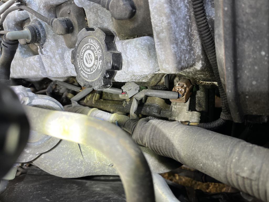 |
|
|
|
| Superhawk996 |
Jun 19 2024, 11:11 AM
Post
#19
|
|
914 Guru Group: Members Posts: 6,502 Joined: 25-August 18 From: Woods of N. Idaho Member No.: 22,428 Region Association: Galt's Gulch |
Oxygen sensor - wires potted in sensor but no boot or strain relief required.
Note: emissions systems are mandated to be warranted by OEM 10 years, 100k miles. Emissions systems are not places that OEMs scrimp on due to the warranty risk as well as risk of widespread compliance recalls. Likewise, this is a very hot location. 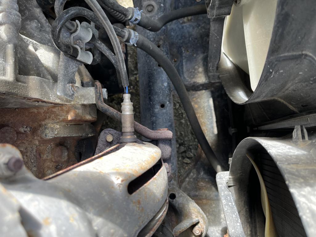 |
|
|
|
| Superhawk996 |
Jun 19 2024, 11:20 AM
Post
#20
|
|
914 Guru Group: Members Posts: 6,502 Joined: 25-August 18 From: Woods of N. Idaho Member No.: 22,428 Region Association: Galt's Gulch |
2012 BMW - 138k miles
Note the varying use - standard connections on non-emissions, non safety components. There is a boot used on the EGR cooler. An emissions related component. The throttle stepper motor also has a boot because the throttle motor is a safety component. When a boot like this is used, the wiring must be secured nearby to ensure the boot isn’t supporting the wiring which will tend to cause intermittent connectivity issues and/or pin pullout. The wiring for the throttle motor is secured at the locations of the orange arrows to help mitigate those risks. 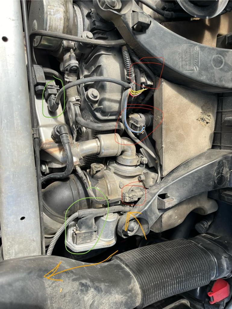 |
|
|
|
|
1 User(s) are reading this topic (1 Guests and 0 Anonymous Users)
0 Members:

|
Lo-Fi Version | Time is now: 30th October 2024 - 09:44 PM |
Invision Power Board
v9.1.4 © 2024 IPS, Inc.