|
|

|
Porsche, and the Porsche crest are registered trademarks of Dr. Ing. h.c. F. Porsche AG.
This site is not affiliated with Porsche in any way. Its only purpose is to provide an online forum for car enthusiasts. All other trademarks are property of their respective owners. |
|
|
  |
| Tom1394racing |
 Nov 7 2024, 04:29 AM Nov 7 2024, 04:29 AM
Post
#441
|
|
Member   Group: Members Posts: 439 Joined: 25-August 07 From: CT Member No.: 8,039 Region Association: North East States 
|
We had a defective CSF cooler. Had to ship the car back to us and then ship back to the customer. CFS warrantied the cooler but we ate $2k in shipping. Geez that is not cool for how much those coolers cost. I just bought one as well. Sounds like it's worth leak testing before install. I did leak test mine but the leak does not appear to be in the radiator portion of the cooler. |
| Luke M |
 Nov 7 2024, 05:39 AM Nov 7 2024, 05:39 AM
Post
#442
|
|
Senior Member    Group: Members Posts: 1,407 Joined: 8-February 05 From: WNY Member No.: 3,574 Region Association: North East States 
|
We had a defective CSF cooler. Had to ship the car back to us and then ship back to the customer. CFS warrantied the cooler but we ate $2k in shipping. Geez that is not cool for how much those coolers cost. I just bought one as well. Sounds like it's worth leak testing before install. I did leak test mine but the leak does not appear to be in the radiator portion of the cooler. I just purchased a new CSF oil cooler as well. I won't be running my engine anytime soon so I guess I better test it for leaks too. |
| Tom1394racing |
 Nov 7 2024, 07:36 AM Nov 7 2024, 07:36 AM
Post
#443
|
|
Member   Group: Members Posts: 439 Joined: 25-August 07 From: CT Member No.: 8,039 Region Association: North East States 
|
I started draining the oil out of the system this morning. Hopefully it won’t be too difficult to change out the cooler. I’ll make sure to report whatever I find. Hopefully it was just a brain fart and the seal is missing.
|
| rgalla9146 |
 Nov 7 2024, 08:54 AM Nov 7 2024, 08:54 AM
Post
#444
|
|
Advanced Member     Group: Members Posts: 4,736 Joined: 23-November 05 From: Paramus NJ Member No.: 5,176 Region Association: None 
|
Tom I think the fan shroud with the removable grey corner piece allows romoval/service of the oil cooler. Not a picnic... but better than engine removal. |
| Tom1394racing |
 Nov 7 2024, 11:11 AM Nov 7 2024, 11:11 AM
Post
#445
|
|
Member   Group: Members Posts: 439 Joined: 25-August 07 From: CT Member No.: 8,039 Region Association: North East States 
|
Tom I think the fan shroud with the removable grey corner piece allows romoval/service of the oil cooler. Not a picnic... but better than engine removal. Yes Rory...I am thinking remove the heat exchanger and the grey corner cooler duct. This should allow both the (2) bottom and (2) top cooler nuts to be removed. Then (2) screws connecting the back tin to the cooler. The cooler should slide down and out at that point. |
| Tom1394racing |
 Nov 7 2024, 06:20 PM Nov 7 2024, 06:20 PM
Post
#446
|
|
Member   Group: Members Posts: 439 Joined: 25-August 07 From: CT Member No.: 8,039 Region Association: North East States 
|
I pulled the cooler this afternoon. I had to make a "relief" cut in the side tin near the cooler to allow it to slide past the case studs. Other that that, the cooler came out pretty easily. All the seals were intact.
It turns out that the leakage was coming from the top cooling passages. The leakage tracks show the oil leaking past the seals and directly down the outer wall of the cooler to the lower studs. 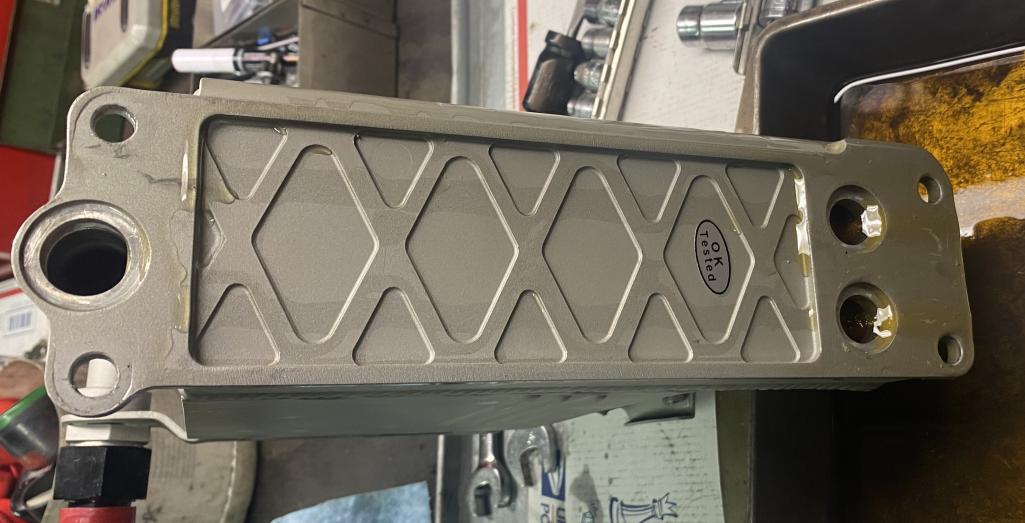 I was a little surprised by this as I did not expect oil to be flowing into the cooler on a stone cold engine. I expected that the engine T-stat would block the flow into the cooler with the engine cold. I also did not expect that the oil would leak past the seals as I had leak tested the cooler using the Stromski test kit. However, the Stromski kit uses the green cooler seals which I used for the test. After the fact, I recalled reading on Pelican that the green seals are much less prone to leakage as compared to the red seals I used when building the engine. I did check the depth of the seal recesses on the CSF cooler and compared them to an OE cooler. No difference. I will retest the cooler for leakage tomorrow with both the red seals and the green seals to see if there is any difference. |
| Justinp71 |
 Nov 7 2024, 06:33 PM Nov 7 2024, 06:33 PM
Post
#447
|
|
Senior Member    Group: Members Posts: 1,629 Joined: 11-October 04 From: Sacramento, CA Member No.: 2,922 Region Association: None 
|
Wow this looks super nice!
I had heard once that there were some oil cooler seals in circulation that were not tall enough, check they all have the same height, should have some squish when tightened up. The MSD on the firewall is great, I have had mine there for along time. Just make sure you have vibration isolation. Also for the coils I run hi-vibration coils but mine is a single mounted on the motor, maybe on the firewall you don't need it. |
| Tom1394racing |
 Nov 8 2024, 12:55 PM Nov 8 2024, 12:55 PM
Post
#448
|
|
Member   Group: Members Posts: 439 Joined: 25-August 07 From: CT Member No.: 8,039 Region Association: North East States 
|
I retested the cooler this morning with the Stromski kit. When I built the engine, I put the seals in the case first and then mounted the cooler on the case. When I did the test, I first mounted the seals in the Stromski sealing plate and then mounted the sealing plate on the cooler to duplicate the build mounting process.
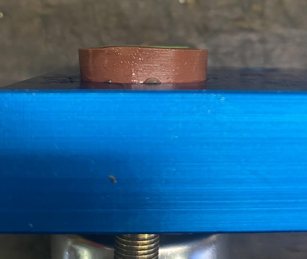
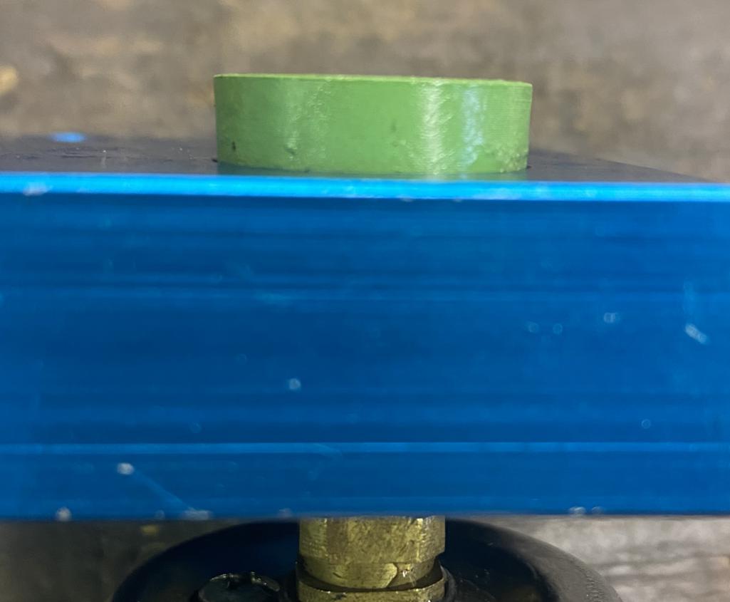
I first used the green seals that came with the kit. They dropped nicely into the recesses on the kit mounting plate. When I laid the plate onto the cooler, I could feel that the seals slipped nicely into the recesses in the cooler holes. I put 40 psi into the cooler dropped into my wash basin full of water. No leaks. I then retested with the red seals I had used in my initial assembly. Same process, onto the plate first and then onto the cooler. I noticed that the red seals were larger in diameter than the green seals and had to be squeezed to fit in the recesses on both the kit mounting plate and the cooler. When the seals were squeezed into the mounting plate, they expanded slightly and did not seat into the cooler recesses. When bolted together, they distorted and did not seal, Failed leak test. I think this is likely the cause of my cooler leak. I found the same problem with the larger red seal for the oil return tube at the bottom of the cooler. Did not fit easily into the recess in the cooler. I will order some green seals and hope to replicate the easy fit of the Stromski seals. |
| rgalla9146 |
 Nov 8 2024, 03:19 PM Nov 8 2024, 03:19 PM
Post
#449
|
|
Advanced Member     Group: Members Posts: 4,736 Joined: 23-November 05 From: Paramus NJ Member No.: 5,176 Region Association: None 
|
Tom I've never seen red seals.
OEM kits have either brown or green seals. Victor Rienz or Elring are the known OEM suppliers. The correct ones require no effort to seat but are able to remain seated in a vertical position. Attached thumbnail(s) 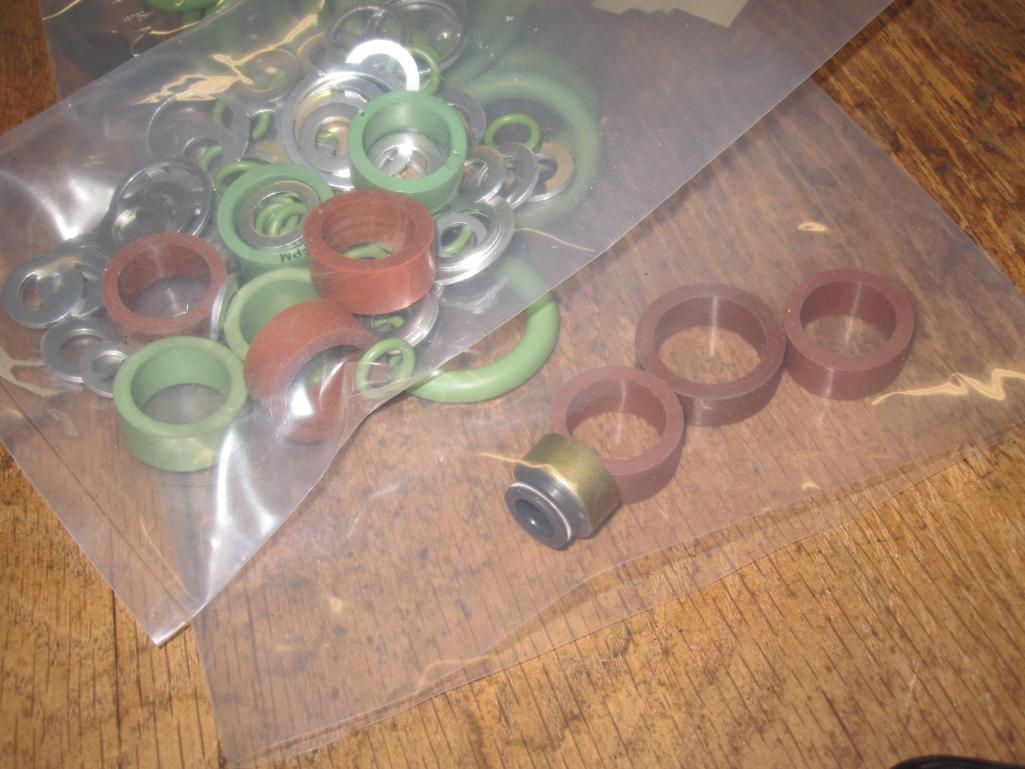
|
| Tom1394racing |
 Nov 8 2024, 04:18 PM Nov 8 2024, 04:18 PM
Post
#450
|
|
Member   Group: Members Posts: 439 Joined: 25-August 07 From: CT Member No.: 8,039 Region Association: North East States 
|
|
| Tom1394racing |
 Nov 8 2024, 05:30 PM Nov 8 2024, 05:30 PM
Post
#451
|
|
Member   Group: Members Posts: 439 Joined: 25-August 07 From: CT Member No.: 8,039 Region Association: North East States 
|
|
| Luke M |
 Nov 11 2024, 05:46 AM Nov 11 2024, 05:46 AM
Post
#452
|
|
Senior Member    Group: Members Posts: 1,407 Joined: 8-February 05 From: WNY Member No.: 3,574 Region Association: North East States 
|
Hi Tom,
Did you figure out the cause of the oil cooler leak? Seals or ? |
| Tom1394racing |
 Nov 12 2024, 07:41 AM Nov 12 2024, 07:41 AM
Post
#453
|
|
Member   Group: Members Posts: 439 Joined: 25-August 07 From: CT Member No.: 8,039 Region Association: North East States 
|
Hi Tom, Did you figure out the cause of the oil cooler leak? Seals or ? Not sure yet. I posted on Pelican and the experts there say they prefer the brown Viton seals but that it should not make a difference. I did order new seals that should arrive later today. I do not think it is a problem with the cooler. I suspect that the original seals did not seat properly during installation. I will reinstall the cooler later this week with whichever seals seem to fit better and make sure they seat properly. I will update the tread with whatever I find. |
| Tom1394racing |
 Nov 13 2024, 05:50 PM Nov 13 2024, 05:50 PM
Post
#454
|
|
Member   Group: Members Posts: 439 Joined: 25-August 07 From: CT Member No.: 8,039 Region Association: North East States 
|
I reinstalled the cooler today. I used the brown Viton seals for the top radiator holes and a new green seal for the lower return tube. I applied plenty of Dow 111 to lubricate both the seals and the recesses in the case and cooler before installation. No sign of leaks in the cooler this time.
I did however find a few leaks in the oil hose connections to the external T-stat that I will have to remedy. The engine itself seems to be leak free. Also, no indication of oil pressure on the combo gauge. I will have to look into this as well before I try a first start. |
| Tom1394racing |
 Nov 18 2024, 06:46 PM Nov 18 2024, 06:46 PM
Post
#455
|
|
Member   Group: Members Posts: 439 Joined: 25-August 07 From: CT Member No.: 8,039 Region Association: North East States 
|
Got my oil system leaks taken care of. Having some issues with the oil pressure gauge.
See here: http://www.914world.com/bbs2/index.php?showtopic=372498 Any suggestions? |
| Tom1394racing |
 Nov 24 2024, 06:37 PM Nov 24 2024, 06:37 PM
Post
#456
|
|
Member   Group: Members Posts: 439 Joined: 25-August 07 From: CT Member No.: 8,039 Region Association: North East States 
|
Latest progress...A couple of steps forward and a step backwards.
I installed a mechanical gauge for the oil pressure to ensure that I indeed have good oil pressure before attempting the first start. The pressure gauge showed 20-30 psi while cranking. So, I connected the fuel pump and the twin MSD systems and cranked the engine over to see if it would fire up. Sure enough, it fired up right away and began to settle into a nice idle. I shut the engine off after around 10 seconds and went in to have lunch, with a big smile on my face, figuring that I would do the 10 -15 minute break-in afterwards. After eating, I went to re-fire the engine and after a couple of revolutions of cranking, the starter quit and I had no power at the dash. No lights, no gauges, no fuel pump... Nothing. As if the ignition switch had failed. I had been cranking the engine over prior to this in 30 sec intervals several times in trying to understand my oil pressure issue. The only difference this time was that both the fuel pump and the MSD ignition systems were connected. I checked all the fuses in the panel in the passenger compartment, all good. So, I disconnected the engine harness from the chassis harness, removed the ignition switch and disconnected the plastic switch harness. I checked the mechanical portion of the switch and found it to be functioning correctly. I am kind of stumped at this point. Any suggestions before I start diving into the wiring? |
| rgalla9146 |
 Nov 24 2024, 08:13 PM Nov 24 2024, 08:13 PM
Post
#457
|
|
Advanced Member     Group: Members Posts: 4,736 Joined: 23-November 05 From: Paramus NJ Member No.: 5,176 Region Association: None 
|
Tom did you try operating the removed ignition switch with a screwdriver ? |
| Tom1394racing |
 Nov 26 2024, 10:06 AM Nov 26 2024, 10:06 AM
Post
#458
|
|
Member   Group: Members Posts: 439 Joined: 25-August 07 From: CT Member No.: 8,039 Region Association: North East States 
|
|
| Tom1394racing |
 Nov 26 2024, 10:17 AM Nov 26 2024, 10:17 AM
Post
#459
|
|
Member   Group: Members Posts: 439 Joined: 25-August 07 From: CT Member No.: 8,039 Region Association: North East States 
|
|
| Tom1394racing |
 Nov 26 2024, 02:23 PM Nov 26 2024, 02:23 PM
Post
#460
|
|
Member   Group: Members Posts: 439 Joined: 25-August 07 From: CT Member No.: 8,039 Region Association: North East States 
|
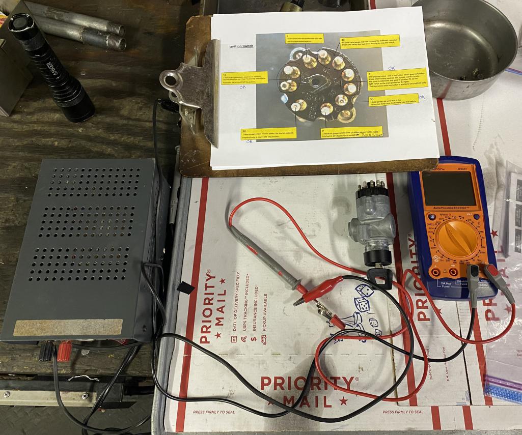
Next, I checked the female connector to the ignition switch that is part of the new Restoration Design 914-6 chassis wiring harness. This harness was modified by Restoration Design to locate dual fuel pumps in the front luggage compartment. There is no fuel pump relay in the circuit. I also disconnected the engine 14 pin from the chassis 14 pin for these tests. Here is where things seemed a bit abnormal.
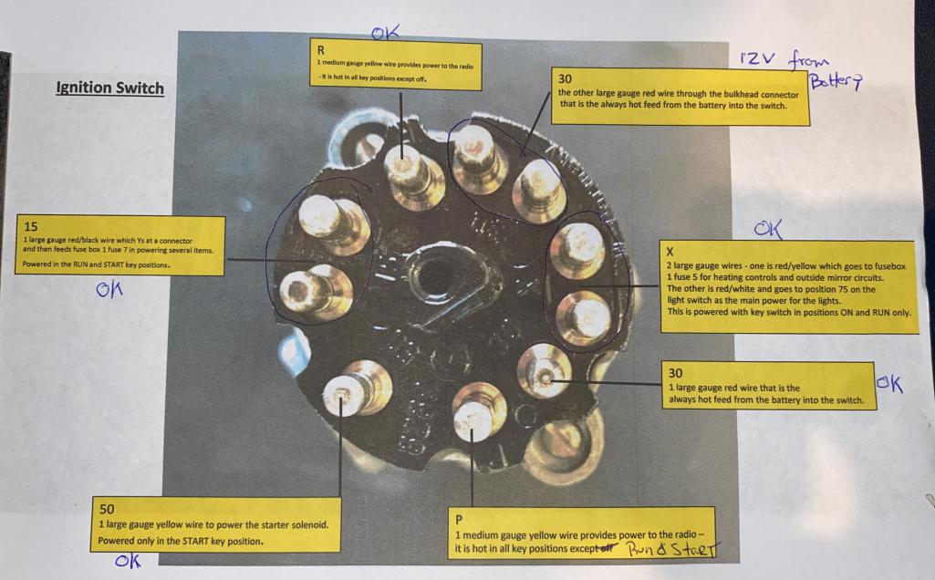
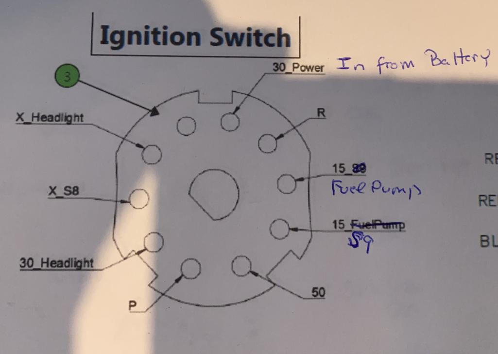 I first verified that connector 30 had 12 volts from the battery. I then verified continuity between: Connector 15 and the fuel pump Connector 15 S9 and S9 on the fuse panel Connector 50 and the yellow starter solenoid wire 14 pin chassis connector Connector X S8 and S8 on the fuse panel All good so far. I did not check continuity on the other ignition switch connectors at this point. Next I applied 12 volts from my DC power supply to connectors 15 fuel pump , 15 S9, 50 and X 58. I used my multimeter to verify 12 volts at each termination (the fuel pump operated as expected). Still all good. Next, I decided to jump the connectors to connector 30 (power in) to mimic the function of the switch. Here is where things got strange. 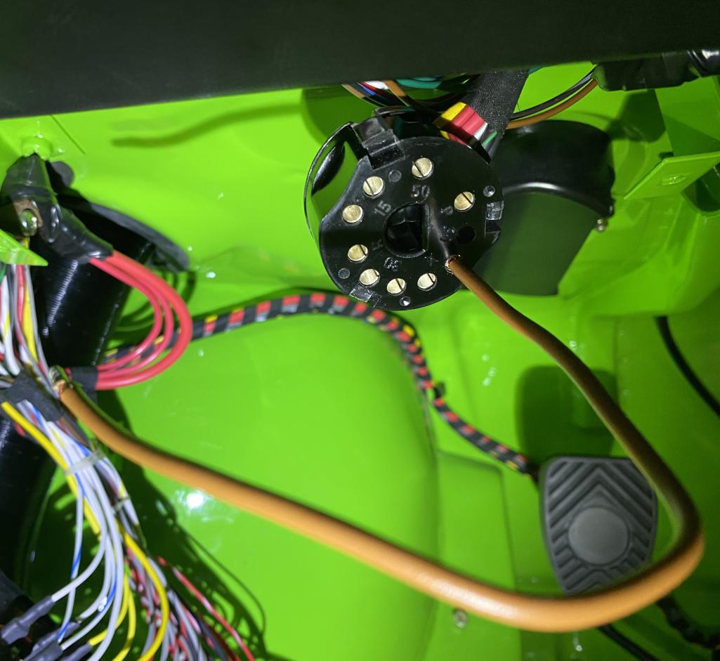 When I bridged from 30 (power in) to 15 fuel pump, there was no power supplied to the fuel pump. When I bridged from 30 (power in) to 15 S9, I got only 6 volts at S9 on the fuse panel. When I bridged 30 (power in) to 50, I got 12 volts at the solenoid wire in the chassis 14 pin connector When I bridged 30 (power in) to X S8, I got zero voltage at S8 on the fuse panel. Using bridged battery power from terminal 30 gives a different result than applying power directly from my 12 volt power source except for the starter solenoid which operated as expected. Very strange…Any ideas? |
  |
1 User(s) are reading this topic (1 Guests and 0 Anonymous Users)
0 Members:

|
Lo-Fi Version | Time is now: 19th April 2025 - 02:52 PM |
Invision Power Board
v9.1.4 © 2025 IPS, Inc.


