|
|

|
Porsche, and the Porsche crest are registered trademarks of Dr. Ing. h.c. F. Porsche AG.
This site is not affiliated with Porsche in any way. Its only purpose is to provide an online forum for car enthusiasts. All other trademarks are property of their respective owners. |
|
|
  |
| bbrock |
 Jul 31 2022, 10:16 AM Jul 31 2022, 10:16 AM
Post
#21
|
|
914 Guru      Group: Members Posts: 5,269 Joined: 17-February 17 From: Montana Member No.: 20,845 Region Association: Rocky Mountains 
|
I went ahead and ordered one of these low voltage disconnect modules. There are DIY circuits available, but just to source parts would cost 3X as much and not be as compact.
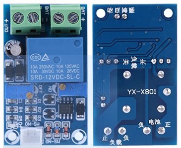 https://www.amazon.com/gp/product/B07RS49D6...5LSJQ&psc=1 This will be installed between the washer pump and 3-way connector with wiring as follows: B+ -> brwn/blk wire from 3-way B- -> chassis ground at washer pump Out + -> + on washer pump (I will change this wire to rd/blk to reflect it is now a switched power wire) This SHOULD leave the relay contacts open when the wiper switch is pulled down into the "J" intermittent position and break the path from the brwn/blk wire to ground. When the lever is pulled back for washer, it should energized the circuit on the module which will sense voltage above the cut on threshold and close the relay contacts allowing 12v to flow to the pump. It should be here later this week and I'll report how it works. (IMG:style_emoticons/default/beerchug.gif) |
| Superhawk996 |
 Jul 31 2022, 10:27 AM Jul 31 2022, 10:27 AM
Post
#22
|
|
914 Guru      Group: Members Posts: 6,907 Joined: 25-August 18 From: Woods of N. Idaho Member No.: 22,428 Region Association: Galt's Gulch 
|
I went ahead and ordered one of these low voltage disconnect modules. More stuff for the "simple" schematic to reflect. (IMG:style_emoticons/default/av-943.gif) I still can't picture it. (IMG:style_emoticons/default/wacko.gif) I stared (sideways (IMG:style_emoticons/default/laugh.gif) ) at the column switch schematic you sent for a while and I'm still not convinced I understand how that column switch is wired and/or where the power is coming from to the intermittent relay when you put it in the J position. I am almost tempted to go find the box that has my manuals and schematics and dig them out. Like you, now that there is a mystery to be solved, I'd love to solve it. However, there is so much yet to be packed, I'm not going backward to dig out reference materials. I trust that you have a plan. (IMG:style_emoticons/default/shades.gif) |
| windforfun |
 Jul 31 2022, 10:32 AM Jul 31 2022, 10:32 AM
Post
#23
|
|
Advanced Member     Group: Members Posts: 2,050 Joined: 17-December 07 From: Blackhawk, CA Member No.: 8,476 Region Association: None 
|
I went ahead and ordered one of these low voltage disconnect modules. More stuff for the "simple" schematic to reflect. (IMG:style_emoticons/default/av-943.gif) I still can't picture it. (IMG:style_emoticons/default/wacko.gif) I stared (sideways (IMG:style_emoticons/default/laugh.gif) ) at the column switch schematic you sent for a while and I'm still not convinced I understand how that column switch is wired and/or where the power is coming from to the intermittent relay when you put it in the J position. I am almost tempted to go find the box that has my manuals and schematics and dig them out. Like you, now that there is a mystery to be solved, I'd love to solve it. However, there is so much yet to be packed, I'm not going backward to dig out reference materials. I trust that you have a plan. (IMG:style_emoticons/default/shades.gif) I know what you mean about deciphering these "schematics." They're "Greek to me" too & I have a MS degree in EE. They're more like block diagrams with unique notation. |
| bbrock |
 Jul 31 2022, 11:29 AM Jul 31 2022, 11:29 AM
Post
#24
|
|
914 Guru      Group: Members Posts: 5,269 Joined: 17-February 17 From: Montana Member No.: 20,845 Region Association: Rocky Mountains 
|
I went ahead and ordered one of these low voltage disconnect modules. More stuff for the "simple" schematic to reflect. (IMG:style_emoticons/default/av-943.gif) I still can't picture it. (IMG:style_emoticons/default/wacko.gif) I stared (sideways (IMG:style_emoticons/default/laugh.gif) ) at the column switch schematic you sent for a while and I'm still not convinced I understand how that column switch is wired and/or where the power is coming from to the intermittent relay when you put it in the J position. I am almost tempted to go find the box that has my manuals and schematics and dig them out. Like you, now that there is a mystery to be solved, I'd love to solve it. However, there is so much yet to be packed, I'm not going backward to dig out reference materials. I trust that you have a plan. (IMG:style_emoticons/default/shades.gif) Power for the intermittent comes from 53 (low speed input to motor). If you mentally move the contact diagrams above 53 and directly bellow 53a through the various positions, you can see 53 is connected to 53a (from the starter switch) on the left contact in switch positions J & 0, and is connected through that left contact in position 1, then disconnected in position 2. Why it is connected to power in position 0 is a bit of a mystery to me, as is what 53e is doing. I'm not even sure what it is connected to at 31b. Isolating the problem by just looking at the part of the circuit modified by adding the washer pump, the pump works fine when connected to S1 (brwn/blk) but the intermittent function does not. Disconnect the pump to break the pathway to ground and the intermittent function works again. Simply, the S1 wire needs to connect to the washer pump when voltage is applied, and be disconnected when it is not. Here, I added the "complicated" part for you. (IMG:style_emoticons/default/biggrin.gif)  |
| Superhawk996 |
 Jul 31 2022, 11:43 AM Jul 31 2022, 11:43 AM
Post
#25
|
|
914 Guru      Group: Members Posts: 6,907 Joined: 25-August 18 From: Woods of N. Idaho Member No.: 22,428 Region Association: Galt's Gulch 
|
You dick (IMG:style_emoticons/default/lol-2.gif) and I use that as your usual badge of honor. (IMG:style_emoticons/default/av-943.gif) 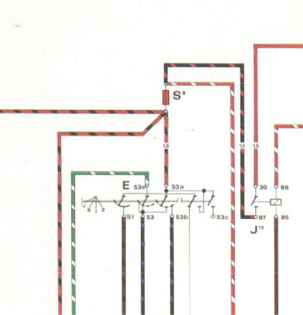 Your comment: "Power for the intermittent comes from 53 (low speed input to motor). If you mentally move the contact diagrams above 53 and directly bellow 53a through the various positions, you can see 53 is connected to 53a (from the starter switch) on the left contact in switch positions J & 0, and is connected through that left contact in position 1, then disconnected in position 2. Why it is connected to power in position 0 is a bit of a mystery to me, as is what 53e is doing. I'm not even sure what it is connected to at 31b. " That green and white wire isn't always power. When the wipers are turned off, it is connected to ground and acts as an inertia brake by putting ground to the armature. it's actual condition (power or ground) depends on the position of the rotary switch that is connected to the wiper motor shaft. As for position J -- the only thing that is ever connected when in position J, is the green and white (53e) to 53. (per comment below - Green/White is the inertia brake) In low speed, the actual 12V power feed is coming through 53a to the set of contacts that also feed 53b when in the 2nd position. Note in the 1st position 53a feeds feeds 53. In the second position (high) then it feeds 53b. What is on the green and white wire (power or ground) is dependent on the position of the 3 track rotary switch that is attached to the motor armature. 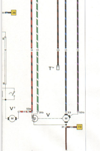 When the motor is parked, I think the green and white will actually have ground on it . . . but I'm not 100% sure and would want to measure this. When the switch is moved to position #1, that ground is interrupted and the 12v power comes over from that other set of contacts fed from 53a to 53. This is why I need the schematic of where (and how - by pin#) your intermittent relay and washer were installed relative to this circuit. It really isn't a simple circuit. I could be wrong, but I think the green and white wire (i.e. the inertia brake) is what grounding your intermittent wiper relay? Obviously I'm not 100% sure. |
| Superhawk996 |
 Jul 31 2022, 12:50 PM Jul 31 2022, 12:50 PM
Post
#26
|
|
914 Guru      Group: Members Posts: 6,907 Joined: 25-August 18 From: Woods of N. Idaho Member No.: 22,428 Region Association: Galt's Gulch 
|
@bbrock
Do you actually have your intermittent relay wired in just like this? 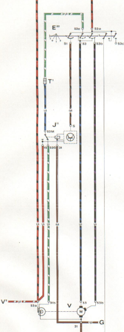 I think that you are saying no. It sounds to me like you are using the motor low speed feed as your control (S terminal) to the intermittent relay rather than the brown/black wire that is only getting 12V when stalk is pulled? Your "schematic" you provided seems to imply that you're using pin 15 as the output from your intermittent relay and that is what is feeding the washer pump? That would not be the same intermittent wiring as the 914/6 & Bowlsby kit. And if I understand your intent correctly, you want: 1) Washer pump operates along with intermittent wipe when you pull the switch? 2) Intermittent wipe operates continuously when the switch is in position J? |
| bbrock |
 Jul 31 2022, 01:42 PM Jul 31 2022, 01:42 PM
Post
#27
|
|
914 Guru      Group: Members Posts: 5,269 Joined: 17-February 17 From: Montana Member No.: 20,845 Region Association: Rocky Mountains 
|
@bbrock Do you actually have your intermittent relay wired in just like this?  I think that you are saying no. It sounds to me like you are using the motor low speed feed as your control (S terminal) to the intermittent relay rather than the brown/black wire that is only getting 12V when stalk is pulled? Your "schematic" you provided seems to imply that you're using pin 15 as the output from your intermittent relay and that is what is feeding the washer pump? That would not be the same intermittent wiring as the 914/6 & Bowlsby kit. Whoops! My bad. I labeled that relay terminal from memory and was too lazy to look up whether it was correct. I do have my relay wired exactly as Jeff outlines in his article. So my complex diagram should have that labeled as 'S.' Sorry about that. To be clear, the brwn/blk wire is the control wire for the intermittent. You're explanation of the grn/wht wire makes sense and I think completes the understanding for me. The brwn/blk wire goes to ground in all positions except "J" and when the lever is pulled back. This circuit flow style schematic makes it impossible to tell the exact wire path of that ground. I think it is through the grn/wht wire. The relay schematic might shed some light on that but I'm too lazy right now. All I need to know is that the brwn/blk wire sometimes works as a ground, sometimes as V+, and sometimes as nothing at all. I suppose that is German ingenuity to use a single wire for multiple purposes but it sure is confusing. (IMG:style_emoticons/default/lol-2.gif) QUOTE And if I understand your intent correctly, you want: 1) Washer pump operates along with intermittent wipe when you pull the switch? 2) Intermittent wipe operates continuously when the switch is in position J? Right, and right now splitting off the brwn/blk wire to the washer (+), then #1 works. If you disconnect that wire from the washer pump which restores the stock wiring config, #2 works. |
| Superhawk996 |
 Jul 31 2022, 01:46 PM Jul 31 2022, 01:46 PM
Post
#28
|
|
914 Guru      Group: Members Posts: 6,907 Joined: 25-August 18 From: Woods of N. Idaho Member No.: 22,428 Region Association: Galt's Gulch 
|
Instead of the kit, I'm branching off the brown/black wire that feeds power to the intermittent relay for cars that have them. 12v is fed to that wire whenever the wiper lever is pulled back for manual pulse wipers, or down into the intermittent position. As I review previous posts to understand what intent was I think this is a faulty assumption. Again you have parts and I'm looking at schematics so I'll trust what you measure. From the schematic -- When that stalk is pulled down, I think you're only connecting 53e (green & white inertia brake) to the low speed motor feed 53. |
| Superhawk996 |
 Jul 31 2022, 01:48 PM Jul 31 2022, 01:48 PM
Post
#29
|
|
914 Guru      Group: Members Posts: 6,907 Joined: 25-August 18 From: Woods of N. Idaho Member No.: 22,428 Region Association: Galt's Gulch 
|
just saw your other post
Yes - the schematics are a bit ambiguous where lines are crossing. My understanding of how Porsche does them is that if lines cross and there is no dot (usually a solid dot) there is no connection. At wire ends there is often a empty (hollow) dot indicating a connection point. |
| bbrock |
 Jul 31 2022, 01:51 PM Jul 31 2022, 01:51 PM
Post
#30
|
|
914 Guru      Group: Members Posts: 5,269 Joined: 17-February 17 From: Montana Member No.: 20,845 Region Association: Rocky Mountains 
|
Instead of the kit, I'm branching off the brown/black wire that feeds power to the intermittent relay for cars that have them. 12v is fed to that wire whenever the wiper lever is pulled back for manual pulse wipers, or down into the intermittent position. As I review previous posts to understand what intent was I think this is a faulty assumption. Again you have parts and I'm looking at schematics so I'll trust what you measure. From the schematic -- When that stalk is pulled down, I think you're only connecting 53e (green & white inertia brake) to the low speed motor feed 53. That post was very early as I was still figuring out how this worked. I corrected it later on. 12v is sent on brwn/blk ONLY when the lever is pulled back, it is disconnected from the circuit when pulled down, and grounded in all other positions. |
| Superhawk996 |
 Jul 31 2022, 01:58 PM Jul 31 2022, 01:58 PM
Post
#31
|
|
914 Guru      Group: Members Posts: 6,907 Joined: 25-August 18 From: Woods of N. Idaho Member No.: 22,428 Region Association: Galt's Gulch 
|
You're explanation of the grn/wht wire makes sense and I think completes the understanding for me. The brwn/blk wire goes to ground in all positions except "J" and when the lever is pulled back. This circuit flow style schematic makes it impossible to tell the exact wire path of that ground. I think it is through the grn/wht wire. The relay schematic might shed some light on that but I'm too lazy right now. No -- that brown / black doesn't get ground though the green/white. Here is where the brown/black gets ground -- it's coming though the NC (normally closed) connection of the pull switch. When the switch is pulled this ground (yellow arrows) is interrupted and 12v is applied as sourced from 53a. 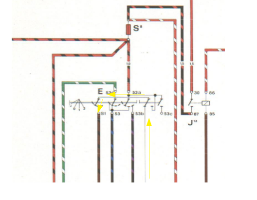 See post 29 again. Where lines cross without a dot (solid or hollow) there is no connection. As stated by @windforfun - - - some of the switch notation is seriously confusing and/or lacking in clarity even to those of us that use schematics heavily. I'll stand corrected if you measure something different. When ever I do this on my car, I do as much "verification" as I can with a DMM that the switch is operating the way I see it on the schematic. I'm not always right. Here is the full current waterfall for that ground circuit. Because it's a solid line and doesn't have a color code or wire gauge, I assume that means that column pull switch is actually sourced from a chassis ground between the steering column and the body. 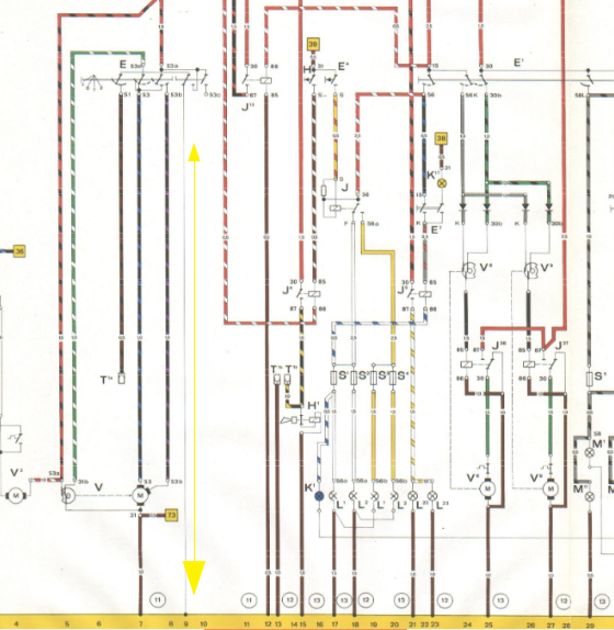 |
| bbrock |
 Jul 31 2022, 01:59 PM Jul 31 2022, 01:59 PM
Post
#32
|
|
914 Guru      Group: Members Posts: 5,269 Joined: 17-February 17 From: Montana Member No.: 20,845 Region Association: Rocky Mountains 
|
just saw your other post Yes - the schematics are a bit ambiguous where lines are crossing. My understanding of how Porsche does them is that if lines cross and there is no dot (usually a solid dot) there is no connection. At wire ends there is often a empty (hollow) dot indicating a connection point. You are right. I've been reading it wrong and it makes even more sense now but doesn't change the diagnosis. Reading it correctly, 53 only gets 12v when in position "1" which is low speed. That makes perfect sense now. I still say that the only wire we really need to be worried about is brwn/blk which is the only one modded by adding the pump, but it's fun to know how the complete circuit works. |
| bbrock |
 Jul 31 2022, 02:07 PM Jul 31 2022, 02:07 PM
Post
#33
|
|
914 Guru      Group: Members Posts: 5,269 Joined: 17-February 17 From: Montana Member No.: 20,845 Region Association: Rocky Mountains 
|
You're explanation of the grn/wht wire makes sense and I think completes the understanding for me. The brwn/blk wire goes to ground in all positions except "J" and when the lever is pulled back. This circuit flow style schematic makes it impossible to tell the exact wire path of that ground. I think it is through the grn/wht wire. The relay schematic might shed some light on that but I'm too lazy right now. No -- that brown / black doesn't get ground though the green/white. Here is where the brown/black gets ground -- it's coming though the NC (normally closed) connection of the pull switch. When the switch is pulled this ground (yellow arrows) is interrupted and 12v is applied as sourced from 53a.  See post 29 again. Where lines cross without a dot (solid or hollow) there is no connection. As stated by @windforfun - - - some of the switch notation is seriously confusing and/or lacking in clarity even to those of us that use schematics heavily. I'll stand corrected if you measure something different. When ever I do this on my car, I do as much "verification" as I can with a DMM that the switch is operating the way I see it on the schematic. I'm not always right. And the intermittent is also getting power from 53a via the relay harness between the relay and wiper motor. |
| bbrock |
 Jul 31 2022, 02:09 PM Jul 31 2022, 02:09 PM
Post
#34
|
|
914 Guru      Group: Members Posts: 5,269 Joined: 17-February 17 From: Montana Member No.: 20,845 Region Association: Rocky Mountains 
|
And I agree about the confusion. I'm not a fan of these circuit flow style schematics. I can see why they did it, but the older schematics are easier to read for me. Not to say they aren't sometimes clear as mud though.
|
| Superhawk996 |
 Jul 31 2022, 02:26 PM Jul 31 2022, 02:26 PM
Post
#35
|
|
914 Guru      Group: Members Posts: 6,907 Joined: 25-August 18 From: Woods of N. Idaho Member No.: 22,428 Region Association: Galt's Gulch 
|
I don't think you'll be able to get the condition where Position J operates the intermittent continuously.
Am I mistaken? |
| bbrock |
 Jul 31 2022, 02:26 PM Jul 31 2022, 02:26 PM
Post
#36
|
|
914 Guru      Group: Members Posts: 5,269 Joined: 17-February 17 From: Montana Member No.: 20,845 Region Association: Rocky Mountains 
|
No -- that brown / black doesn't get ground though the green/white. Here is where the brown/black gets ground -- it's coming though the NC (normally closed) connection of the pull switch. When the switch is pulled this ground (yellow arrows) is interrupted and 12v is applied as sourced from 53a.  What I meant about not being able to tell the pathway where that push switch is being grounded. That thin black line where your arrow is pointing up is doesn't say much to me other than it is grounded. Maybe through the little copper tab that gets lost on the switch cluster? I don't remember what stops working when that goes missing. I was thinking it was the horn but maybe more grounds through there. Anyway, the DMM says this. Pull back the lever and you get 12v out of brwn/blk. Pull down on the lever and you get 0v and infinite Ohms to ground. That's really all I needed to figure out how to make the washer pump work the way I want and confirmed by testing with the wire connected and disconnected to the pump. Pretty simple. All the rest is just satisfying curiosity. |
| bbrock |
 Jul 31 2022, 02:31 PM Jul 31 2022, 02:31 PM
Post
#37
|
|
914 Guru      Group: Members Posts: 5,269 Joined: 17-February 17 From: Montana Member No.: 20,845 Region Association: Rocky Mountains 
|
I don't think you'll be able to get the condition where Position J operates the intermittent continuously Am I mistaken? You are mistaken which I have demonstrated by doing it manually. All I have to do is disconnect the brown/black wire from the washer pump and the continuous intermittent function is restored. The LVD module I order should simply automate that process by connecting brown/black to the pump only when 12v is present on the wire, and disconnecting when it is not. |
| lesorubcheek |
 Jul 31 2022, 02:54 PM Jul 31 2022, 02:54 PM
Post
#38
|
|
Member   Group: Members Posts: 193 Joined: 21-April 21 From: Florida Member No.: 25,463 Region Association: South East States |
Anyway, the DMM says this. Pull back the lever and you get 12v out of brwn/blk. Pull down on the lever and you get 0v and infinite Ohms to ground. That's really all I needed to figure out how to make the washer pump work the way I want and confirmed by testing with the wire connected and disconnected to the pump. Pretty simple. All the rest is just satisfying curiosity. This makes sense, I think. It's obviously a fact since you see it on the meter. So please see if this is correct. 1. When the wiper stalk is in positions 0, 1 or 2, the intermittent relay can receive +12V when the stalk is pulled back as has been explained previously via the black/brown wire connecting S1 of the switch to S of the relay. 2. When the stalk is in positions 0, 1 or 2,and the lever is not pulled back, the intermittent relay is receiving a ground at S via the black/brown wire. 3. When the stalk is in the J position, the relay at S is seeing an open circuit. For the longest time item 3 is what wouldn't sink in, but finally I see where the relay has a +12v input on connector 15. Just kept thinking the relay must get a +12v input on S in order to work, but it appears the real power for the relay is through connector 15 and S is just a 3 state input, either ground +12v or open circuit. The logic then I guess would be that when S is ground, the relay remains off, if a +12v is seen, it activates for once or twice, then shuts off and when open circuit is at S, it activates using whatever time interval it's set up to cycle. I sure hope this is correct because I'm running out of Tylenol. Dan |
| Superhawk996 |
 Jul 31 2022, 02:58 PM Jul 31 2022, 02:58 PM
Post
#39
|
|
914 Guru      Group: Members Posts: 6,907 Joined: 25-August 18 From: Woods of N. Idaho Member No.: 22,428 Region Association: Galt's Gulch 
|
(IMG:style_emoticons/default/idea.gif)
Ok now I think I understand your idea better. I'm used to thinking input is on the left side. So this is what you meant?  So when you pull the stalk, you trigger the intermittent 12v input (S) to the relay. Simultaneously the the wiper pump is on as long as 12v is present. Then when the black/brown returns to ground the pump stops, the wiper pump is decoupled, and the intermittent stays active. (IMG:style_emoticons/default/idea.gif) Will be interesting to see if it indeed works. But by the time you have to put that little gizmo in there I'm thinking we're back to an Arduino (in effect) (IMG:style_emoticons/default/poke.gif) (IMG:style_emoticons/default/laugh.gif) But if it works as you propose . . . . we'll all owe you a beer |
| bbrock |
 Jul 31 2022, 03:47 PM Jul 31 2022, 03:47 PM
Post
#40
|
|
914 Guru      Group: Members Posts: 5,269 Joined: 17-February 17 From: Montana Member No.: 20,845 Region Association: Rocky Mountains 
|
(IMG:style_emoticons/default/idea.gif) Ok now I think I understand your idea better. I'm used to thinking input is on the left side. So this is what you meant?  So when you pull the stalk, you trigger the intermittent 12v input (S) to the relay. Simultaneously the the wiper pump is on as long as 12v is present. Then when the black/brown returns to ground the pump stops, the wiper pump is decoupled, and the intermittent stays active. (IMG:style_emoticons/default/idea.gif) Will be interesting to if it indeed works. But by the time you have to put that little gizmo in there I'm thinking we're back to an Arduino (in effect) (IMG:style_emoticons/default/poke.gif) (IMG:style_emoticons/default/laugh.gif) But if it works as you propose . . . . we'll all owe you a beer Correct. It's all about opening and closing the relay that connects B+ to Out+ depending on what brwn/blk is doing on the B+ side. Where I could get screwed is if the sensor circuit of B+/B- allows current to flow to ground even when the relay is open. It shouldn't because the intended use case of the LVD is to disconnect a battery from its load if the voltage drops below a set threshold but we shall see. Well, it is much simpler than an arduino on my end because I don't have to design and build the circuit around the arduino. I also don't think an arduino would work well here. If the arduino were powered by the brwn/blk wire, it would have to boot and load the sketch every time the washer lever was pulled. That would cause a significant delay. The alternative would be to power the arduino independently which is more wire, a more complicated circuit, and another potential failure point. If this works, it is close to the original one-wire idea. I do have to add a short ground wire from B- to ground to read "battery" voltage, but you sort of have to do that to ground the pump anyway. I'll do that with a "Y" wire with a ring connector to attach to chassis ground at the pump mount, another with spade to plug into pump (-), and a bare end to clamp into the B- terminal on the LVD. Should still be very compact and tidy. Just please don't leak to ground! (IMG:style_emoticons/default/hands.gif) (IMG:style_emoticons/default/smile.gif) |
  |
1 User(s) are reading this topic (1 Guests and 0 Anonymous Users)
0 Members:

|
Lo-Fi Version | Time is now: 2nd April 2025 - 11:40 PM |
Invision Power Board
v9.1.4 © 2025 IPS, Inc.


