|
|

|
Porsche, and the Porsche crest are registered trademarks of Dr. Ing. h.c. F. Porsche AG.
This site is not affiliated with Porsche in any way. Its only purpose is to provide an online forum for car enthusiasts. All other trademarks are property of their respective owners. |
|
|
  |
| Superhawk996 |
 Jul 31 2022, 04:10 PM Jul 31 2022, 04:10 PM
Post
#41
|
|
914 Guru      Group: Members Posts: 6,907 Joined: 25-August 18 From: Woods of N. Idaho Member No.: 22,428 Region Association: Galt's Gulch 
|
Now that I've had some time to think about the LVD solution here are some thoughts.
I think the same overall goal of disconnecting the pump ground path from the intermittent relay could be achieved with a simple MOSFET transistor. The control input to the MOSFET gate would be the 12v input from Black/Brown stalk switch, I can't tell from the specs for the proposed LDV if it can handle inductive loads or is just for resistive load like a light, LED, or battery. Inductive loads (relays, motors) can generate voltage spikes that will damage electronic components when they are shut off abruptly. If a MOSFET were being used to switch the washer pump, I'd say that you would want to put a flyback diode in the circuit to protect the circuit. Can't tell if the LVD proposed has internal flyback diodes. Maybe, maybe not depending on whether they designed it to handle inductive loads. You could easily add your own externally. For $8 - can't go wrong even it it eventually dies from an inductive load. At that point you could switch to a MOSFET switch like this for around the same cost and is even smaller: https://www.amazon.com/ANMBEST-High-Power-A...-spons&th=1 |
| Spoke |
 Jul 31 2022, 04:44 PM Jul 31 2022, 04:44 PM
Post
#42
|
|
Jerry      Group: Members Posts: 7,145 Joined: 29-October 04 From: Allentown, PA Member No.: 3,031 Region Association: None 
|
I've been following this discussion but haven't chimed in because I'm severely confused on the operation.
I'm trying to understand this switch function. Please let me know if I've got this correct. Switch positions: J : Stalk pulled back; Relates to left-most selection of the contacts. 0 : Wipers off 1 : Wipers on low speed 2 : Wipers on high speed. Contact S1: J : No connection 0 : Ground 1 : Ground 2 : 12V Did I get this right? 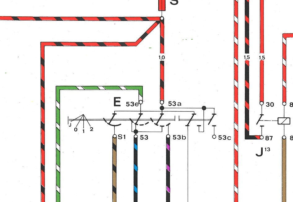 |
| bbrock |
 Jul 31 2022, 04:57 PM Jul 31 2022, 04:57 PM
Post
#43
|
|
914 Guru      Group: Members Posts: 5,269 Joined: 17-February 17 From: Montana Member No.: 20,845 Region Association: Rocky Mountains 
|
Now that I've had some time to think about the LVD solution here are some thoughts. I think the same overall goal of disconnecting the pump ground path from the intermittent relay could be achieved with a simple MOSFET transistor. The control input to the MOSFET gate would be the 12v input from Black/Brown stalk switch, I can't tell from the specs for the proposed LDV if it can handle inductive loads or is just for resistive load like a light, LED, or battery. Inductive loads (relays, motors) can generate voltage spikes that will damage electronic components when they are shut off abruptly. If a MOSFET were being used to switch the washer pump, I'd say that you would want to put a flyback diode in the circuit to protect the circuit. Can't tell if the LVD proposed has internal flyback diodes. Maybe, maybe not depending on whether they designed it to handle inductive loads. You could easily add your own externally. For $8 - can't go wrong even it it eventually dies from an inductive load. At that point you could switch to a MOSFET switch like this for around the same cost and is even smaller: https://www.amazon.com/ANMBEST-High-Power-A...-spons&th=1 Don't think that one will work. It switches gnd but not vcc. I need the other way round. There is a question and couple reviews about it. I looked at mosfet circuits but the potential for a plug-n-play solution for <$8 seemed a no brainer. I found a couple DIY circuits that look very similar to this module when built. They both used flyback diodes. Hoping this does the same. I think I spy at least 3 diodes in the pics on Amazon. Can't say for sure. |
| bbrock |
 Jul 31 2022, 05:09 PM Jul 31 2022, 05:09 PM
Post
#44
|
|
914 Guru      Group: Members Posts: 5,269 Joined: 17-February 17 From: Montana Member No.: 20,845 Region Association: Rocky Mountains 
|
I've been following this discussion but haven't chimed in because I'm severely confused on the operation. I'm trying to understand this switch function. Please let me know if I've got this correct. Switch positions: J : Stalk pulled back; Relates to left-most selection of the contacts. 0 : Wipers off 1 : Wipers on low speed 2 : Wipers on high speed. Contact S1: J : No connection 0 : Ground 1 : Ground 2 : 12V Did I get this right? Ah! There is something I should have explained early that will not be obvious unless you have messed with the intermittent option. J is lever pulled down and is not available by default. There is a plastic tab in the switch that has to be broken off to allow the lever to move one click down from the off position. So to complete what you have: Switch positions: J : Stalk pulled down - intermittent; Relates to left-most selection of the contacts. 0 : Wipers off 1 : Wipers on low speed 2 : Wipers on high speed. P: Stalk pulled back - activate short cycle of wipers. Contact S1: J : No connection 0 : Ground 1 : Ground 2 : Ground P : 12v |
| Superhawk996 |
 Jul 31 2022, 05:17 PM Jul 31 2022, 05:17 PM
Post
#45
|
|
914 Guru      Group: Members Posts: 6,907 Joined: 25-August 18 From: Woods of N. Idaho Member No.: 22,428 Region Association: Galt's Gulch 
|
Don't think that one will work. It switches gnd but not vcc. I need the other way round. There is a question and couple reviews about it. Not a big deal to have the MOSFET switching Ground. The resistance between the gate (the control) and either the source or drain is so high that the intermittent relay that will be sharing the gate connection will never "see" the ground through the gate - source junction. |
| Spoke |
 Jul 31 2022, 06:10 PM Jul 31 2022, 06:10 PM
Post
#46
|
|
Jerry      Group: Members Posts: 7,145 Joined: 29-October 04 From: Allentown, PA Member No.: 3,031 Region Association: None 
|
Ah! There is something I should have explained early that will not be obvious unless you have messed with the intermittent option. J is lever pulled down and is not available by default. There is a plastic tab in the switch that has to be broken off to allow the lever to move one click down from the off position. So to complete what you have: Switch positions: J : Stalk pulled down - intermittent; Relates to left-most selection of the contacts. 0 : Wipers off 1 : Wipers on low speed 2 : Wipers on high speed. P: Stalk pulled back - activate short cycle of wipers. Contact S1: J : No connection 0 : Ground 1 : Ground 2 : Ground P : 12v @bbrock OK, so for position P stalk pulled back, does that move these 2 contacts? I wonder if the double horizontal lines broken between the 2 contacts means when the stalk is pulled back. If so, it looks like you want to connect the washer motor to 53c which looks like it is not wired out. 53c is open unless the stalk is pulled back. So you had the washer motor connected to S1, correct? Pull back on the stalk and the washer and wipers go. But since the motor is connected from S1 to ground, the motor shows S1 a ground connection thus the J, 0, 1, 2 position of S1 are all ground and the intermittent wipers do not work. Does this sound plausible? Attached image(s) 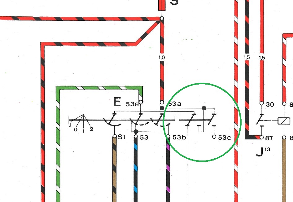
|
| Spoke |
 Jul 31 2022, 06:31 PM Jul 31 2022, 06:31 PM
Post
#47
|
|
Jerry      Group: Members Posts: 7,145 Joined: 29-October 04 From: Allentown, PA Member No.: 3,031 Region Association: None 
|
Now that I've had some time to think about the LVD solution here are some thoughts. I think the same overall goal of disconnecting the pump ground path from the intermittent relay could be achieved with a simple MOSFET transistor. The control input to the MOSFET gate would be the 12v input from Black/Brown stalk switch, I can't tell from the specs for the proposed LDV if it can handle inductive loads or is just for resistive load like a light, LED, or battery. Inductive loads (relays, motors) can generate voltage spikes that will damage electronic components when they are shut off abruptly. If a MOSFET were being used to switch the washer pump, I'd say that you would want to put a flyback diode in the circuit to protect the circuit. Can't tell if the LVD proposed has internal flyback diodes. Maybe, maybe not depending on whether they designed it to handle inductive loads. You could easily add your own externally. For $8 - can't go wrong even it it eventually dies from an inductive load. At that point you could switch to a MOSFET switch like this for around the same cost and is even smaller: https://www.amazon.com/ANMBEST-High-Power-A...-spons&th=1 Don't think that one will work. It switches gnd but not vcc. I need the other way round. There is a question and couple reviews about it. I looked at mosfet circuits but the potential for a plug-n-play solution for <$8 seemed a no brainer. I found a couple DIY circuits that look very similar to this module when built. They both used flyback diodes. Hoping this does the same. I think I spy at least 3 diodes in the pics on Amazon. Can't say for sure. @bbrock I think I agree with you about the switching. The intermittent relay only functions in the J position when S1 is open. Thus grounding pin S on the relay will disable it. This is why tapping the washer motor on S1 to ground disabled the relay. Therefore it can be assumed that the input pin S on the relay has an internal pull-up circuit to activate it when the net connected to pin S is open circuited and pin S voltage will float upwards to some positive voltage. Is this the voltage you measured or was going to measure? If pin S does float upwards then putting a FET input on pin S will likely turn on the washer when the intermittent relay is active (in J position). |
| bbrock |
 Jul 31 2022, 06:45 PM Jul 31 2022, 06:45 PM
Post
#48
|
|
914 Guru      Group: Members Posts: 5,269 Joined: 17-February 17 From: Montana Member No.: 20,845 Region Association: Rocky Mountains 
|
@bbrock OK, so for position P stalk pulled back, does that move these 2 contacts? I wonder if the double horizontal lines broken between the 2 contacts means when the stalk is pulled back. If so, it looks like you want to connect the washer motor to 53c which looks like it is not wired out. 53c is open unless the stalk is pulled back. So you had the washer motor connected to S1, correct? Pull back on the stalk and the washer and wipers go. But since the motor is connected from S1 to ground, the motor shows S1 a ground connection thus the J, 0, 1, 2 position of S1 are all ground and the intermittent wipers do not work. Does this sound plausible? Yes on all counts. I think 53c is indeed the correct (and factory according to @lesorubcheeks ) way to connect the washer. It would require adding a wire, and possibly a pin to the switch connector to run through the bulkhead and over to the washer pump. I don't know about you all, but working on anything in the steering column is a recipe for a bad mood for me. Much of that is because the connectors for my signal and wiper switches fit really tight so I have to pull the knee pad to get sufficient access to unplug them. Plus, I don't like running stray wires through the car. Had I thought of this when I was rebuilding the harness, I might have added a 53c wire. Sir Andy and Jeff Bowlsby drew my attention to the S1 wire being powered in the P position on the lever, and now I'm like a dog with a bone. If this works, the conversion bits will cost < $50 which includes pump, LVD and enclosure, connectors, and wire, and I'll retain my intermittent function. The best part is the whole retrofit takes place up front except to pull the rubber washer hoses off the plunger valve on the switch. That can be done from under the dash without taking anything apart. Up front, you have to remove the washer bottle, fuel tank filler neck, and charcoal canister to gain access to everything. Much easier IMO, than working on the column. For cars not running intermittent wipers, it's looking like replacing the wiper plunger valve with a microswitch was never necessary for cars that have the S1 wire in them. For those, you can just dig the end of the wire out of the harness per Jeff's instructions, and extend it to plug into the washer pump and be done with it! |
| bbrock |
 Jul 31 2022, 06:56 PM Jul 31 2022, 06:56 PM
Post
#49
|
|
914 Guru      Group: Members Posts: 5,269 Joined: 17-February 17 From: Montana Member No.: 20,845 Region Association: Rocky Mountains 
|
I think I agree with you about the switching. The intermittent relay only functions in the J position when S1 is open. Thus grounding pin S on the relay will disable it. This is why tapping the washer motor on S1 to ground disabled the relay. Therefore it can be assumed that the input pin S on the relay has an internal pull-up circuit to activate it when the net connected to pin S is open circuited and pin S voltage will float upwards to some positive voltage. Is this the voltage you measured or was going to measure? Yes, but the voltage readings are small. In the J position with the washer disconnected, I read ~4-11mV which cycles repeatedly. I didn't time the cycles but they seemed like they might be about what the wiper intervals are. Does that sound right? QUOTE If pin S does float upwards then putting a FET input on pin S will likely turn on the washer when the intermittent relay is active (in J position). This sounds interesting except I don't want the washer to run in the J position. Washer should run only in P position and only the intermittent relay should run in J position. I shouldn't have called this a "simple" circuit before. I should have called it a German circuit. Simple in design but complex in function. (IMG:style_emoticons/default/lol-2.gif) |
| Spoke |
 Jul 31 2022, 07:39 PM Jul 31 2022, 07:39 PM
Post
#50
|
|
Jerry      Group: Members Posts: 7,145 Joined: 29-October 04 From: Allentown, PA Member No.: 3,031 Region Association: None 
|
Yes, but the voltage readings are small. In the J position with the washer disconnected, I read ~4-11mV which cycles repeatedly. I didn't time the cycles but they seemed like they might be about what the wiper intervals are. Does that sound right? I would think there would be more voltage deflection than a couple of millivolts. Assuming you had it on DC mode. I wonder what the AC mode would read. If this were a voltage ramp you might get different reading on AC mode. This is good though because the FET circuit may not have enough resistance to ground to inhibit the intermittent relay and there's not enough voltage to turn the FET on. |
| bbrock |
 Jul 31 2022, 08:42 PM Jul 31 2022, 08:42 PM
Post
#51
|
|
914 Guru      Group: Members Posts: 5,269 Joined: 17-February 17 From: Montana Member No.: 20,845 Region Association: Rocky Mountains 
|
Yes, but the voltage readings are small. In the J position with the washer disconnected, I read ~4-11mV which cycles repeatedly. I didn't time the cycles but they seemed like they might be about what the wiper intervals are. Does that sound right? I would think there would be more voltage deflection than a couple of millivolts. Assuming you had it on DC mode. I wonder what the AC mode would read. If this were a voltage ramp you might get different reading on AC mode. This is good though because the FET circuit may not have enough resistance to ground to inhibit the intermittent relay and there's not enough voltage to turn the FET on. Yeah, I just wrote those readings off as noise. I didn't think to measure AC. the relay is kind of a pain to get to with the charcoal canister in place, but next time I'm in there, I'll see if I can get some AC readings. |
| Superhawk996 |
 Aug 1 2022, 06:38 AM Aug 1 2022, 06:38 AM
Post
#52
|
|
914 Guru      Group: Members Posts: 6,907 Joined: 25-August 18 From: Woods of N. Idaho Member No.: 22,428 Region Association: Galt's Gulch 
|
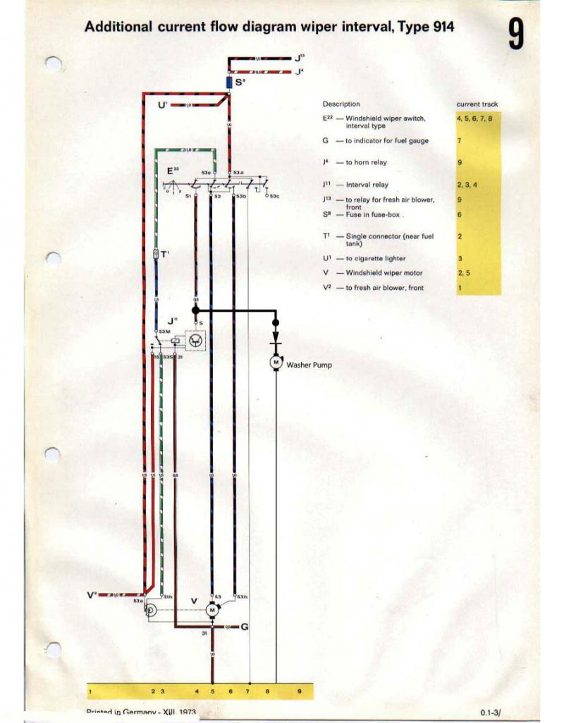
I shouldn't have called this a "simple" circuit before. I should have called it a German circuit. Simple in design but complex in function. (IMG:style_emoticons/default/lol-2.gif) Well said. (IMG:style_emoticons/default/aktion035.gif) That is why I love schematics. I've messed with that stalk switch about 20 years ago but no way to recall all that from memory. The 3 track rotary switch on the motor armature and the inertia brake function further complicate things. Schematics . . . Schematics . . . Schematics. Must have for troubleshooting. FYI - I was able to locate all those schematics on the interwebz so I didn't end up having to pull my reference materials out of packing boxes. You're still a dick for making me find the schematics to help you . . . (IMG:style_emoticons/default/av-943.gif) But then again, I do owe you for letting me drive your car! Please do put up a proper "How To" write up once you get this whole thing sorted. It really should get pinned over in the classics section. |
| Superhawk996 |
 Aug 1 2022, 06:53 AM Aug 1 2022, 06:53 AM
Post
#53
|
|
914 Guru      Group: Members Posts: 6,907 Joined: 25-August 18 From: Woods of N. Idaho Member No.: 22,428 Region Association: Galt's Gulch 
|
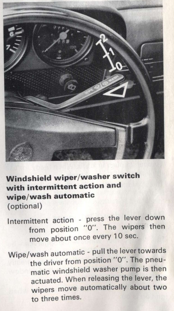
Here's the blurb from the 73' owner's manual on how intermittent works with the factory graphic
 |
| bbrock |
 Aug 1 2022, 08:39 AM Aug 1 2022, 08:39 AM
Post
#54
|
|
914 Guru      Group: Members Posts: 5,269 Joined: 17-February 17 From: Montana Member No.: 20,845 Region Association: Rocky Mountains 
|
I shouldn't have called this a "simple" circuit before. I should have called it a German circuit. Simple in design but complex in function. (IMG:style_emoticons/default/lol-2.gif) Well said. (IMG:style_emoticons/default/aktion035.gif) That is why I love schematics. I've messed with that stalk switch about 20 years ago but no way to recall all that from memory. The 3 track rotary switch on the motor armature and the inertia brake function further complicate things. Schematics . . . Schematics . . . Schematics. Must have for troubleshooting. FYI - I was able to locate all those schematics on the interwebz so I didn't end up having to pull my reference materials out of packing boxes. You're still a dick for making me find the schematics to help you . . . (IMG:style_emoticons/default/av-943.gif) But then again, I do owe you for letting me drive your car! Please do put up a proper "How To" write up once you get this whole thing sorted. It really should get pinned over in the classics section. Didn't I post the full schematic of the circuit at the bottom of page 1? (IMG:style_emoticons/default/confused24.gif) I do appreciate the help. It's good to have multiple eyes thinking through the problem. I may revisit a simple MOSFET circuit. I think it might be possible with just the FET, a couple resistors and a diode which would be simpler and fully solid state compared with the LVD module. Will start with LVD and go from there. I still say we didn't need the full schematic to troubleshoot this problem though. We only needed to know how the S1 wire is supposed to behave because that is the only wire modified by connecting the pump. The switch diagram tells the whole story on that: Open in position "J", 12v, in Position "0", and grounded in all others. That provides enough info to work on solutions. The rest was was fun and interesting, and I learned a lot more about how to read these circuit flow style schematics, but not mission critical. Interesting through that the old style schematics don't provide nearly enough detail to even figure out that one wire. Doesn't even include the intermittent wire or position. 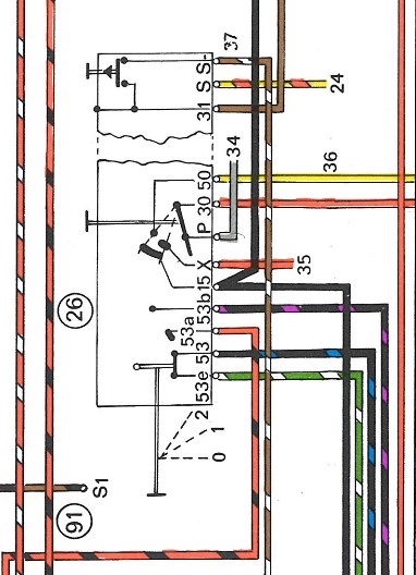 Thinking about bench testing the LVD module when it arrives. I think the critical tests will be that resistance between B+ and B-, and between B+ and Out+ need to be open with 0v on the brwn/blk wire. Resistance between B+ and Out+ should be near 0 ohms above ~10v on brwn/blk, and the resistance needs to drop without significant lag when the voltage is applied. Anything else I should be looking for? |
| Superhawk996 |
 Aug 1 2022, 09:03 AM Aug 1 2022, 09:03 AM
Post
#55
|
|
914 Guru      Group: Members Posts: 6,907 Joined: 25-August 18 From: Woods of N. Idaho Member No.: 22,428 Region Association: Galt's Gulch 
|
I still say we didn't need the full schematic to troubleshoot this problem though. I did . . . just because that is the way I'm wired (pun intended) and was trained. Probably the biggest piece for me was understanding how you had the intermittent relay wired in. For me, I need to see the big picture 1st before I can understand the details of what you had done. Words aren't good at conveying electrical circuit information. That is why schematics were invented. I'm just hoping that you come up with a nice solution that allows operation of both the electric washer pump AND intermittent wipers since that is where I want to end up. |
| lesorubcheek |
 Aug 1 2022, 12:03 PM Aug 1 2022, 12:03 PM
Post
#56
|
|
Member   Group: Members Posts: 193 Joined: 21-April 21 From: Florida Member No.: 25,463 Region Association: South East States |
If the goal is to have an open circuit at S on the intermittent relay, a very simple solution may also be just adding a diode inline. I tested a 5 amp diode in a simple circuit with a 12v bulb and the meter shows 1.3 M ohms to ground on the side that feeds the 12V, which is where the tap is presently the relay. It's not an open circuit, but may be high enough for the intermittent function to work in the J position. It'd be a quick and easy test. Just a thought.
 Dan |
| bbrock |
 Aug 1 2022, 01:40 PM Aug 1 2022, 01:40 PM
Post
#57
|
|
914 Guru      Group: Members Posts: 5,269 Joined: 17-February 17 From: Montana Member No.: 20,845 Region Association: Rocky Mountains 
|
I did . . . just because that is the way I'm wired (pun intended) and was trained. Yeah, I think it's a difference between engineering and ecology. The global ecosystem wasn't built by people so there is not blueprint or schematic of how it works. The scale and seemingly infinite variables is beyond human comprehension. The global circulation model is the most complex computer model ever developed, and only explains a tiny piece of our biosphere. We are good at homing in on just the subsystems that could be affected by the thing we are trying to understand. QUOTE I'm just hoping that you come up with a nice solution that allows operation of both the electric washer pump AND intermittent wipers since that is where I want to end up. To be fair, a good solution already exists. The full Car Magic conversion kits is something like $70 and provides everything needed to have electric washers and intermittent working as the factory intended. It just requires more aggressive modifications, labor, and $ than what I hope to accomplish here. The Car Magic kit is sitting on my coffee table just in case... (IMG:style_emoticons/default/biggrin.gif) |
| Spoke |
 Aug 1 2022, 05:08 PM Aug 1 2022, 05:08 PM
Post
#58
|
|
Jerry      Group: Members Posts: 7,145 Joined: 29-October 04 From: Allentown, PA Member No.: 3,031 Region Association: None 
|
If the goal is to have an open circuit at S on the intermittent relay, a very simple solution may also be just adding a diode inline. I tested a 5 amp diode in a simple circuit with a 12v bulb and the meter shows 1.3 M ohms to ground on the side that feeds the 12V, which is where the tap is presently the relay. It's not an open circuit, but may be high enough for the intermittent function to work in the J position. It'd be a quick and easy test. Just a thought.  Dan (IMG:style_emoticons/default/agree.gif) If indeed there is little voltage on this net when the intermittent relay is active then the diode or two would be a simple solution. |
| bbrock |
 Aug 1 2022, 06:18 PM Aug 1 2022, 06:18 PM
Post
#59
|
|
914 Guru      Group: Members Posts: 5,269 Joined: 17-February 17 From: Montana Member No.: 20,845 Region Association: Rocky Mountains 
|
If the goal is to have an open circuit at S on the intermittent relay, a very simple solution may also be just adding a diode inline. I tested a 5 amp diode in a simple circuit with a 12v bulb and the meter shows 1.3 M ohms to ground on the side that feeds the 12V, which is where the tap is presently the relay. It's not an open circuit, but may be high enough for the intermittent function to work in the J position. It'd be a quick and easy test. Just a thought. Dan (IMG:style_emoticons/default/agree.gif) It indeed there is little voltage on this net when the intermittent relay is active then the diode or two would be a simple solution. You have me curious. Did a little reading to learn about forward voltage. Sounds promising. I should have an assortment of diodes in the bin. Any recommendations on what to try? |
| lesorubcheek |
 Aug 1 2022, 06:34 PM Aug 1 2022, 06:34 PM
Post
#60
|
|
Member   Group: Members Posts: 193 Joined: 21-April 21 From: Florida Member No.: 25,463 Region Association: South East States |
If the goal is to have an open circuit at S on the intermittent relay, a very simple solution may also be just adding a diode inline. I tested a 5 amp diode in a simple circuit with a 12v bulb and the meter shows 1.3 M ohms to ground on the side that feeds the 12V, which is where the tap is presently the relay. It's not an open circuit, but may be high enough for the intermittent function to work in the J position. It'd be a quick and easy test. Just a thought. Dan (IMG:style_emoticons/default/agree.gif) It indeed there is little voltage on this net when the intermittent relay is active then the diode or two would be a simple solution. You have me curious. Did a little reading to learn about forward voltage. Sounds promising. I should have an assortment of diodes in the bin. Any recommendations on what to try? We recently used some 20A 50V Schottkys for isolating the turn signals flashing when using the remote key lock. Gross overkill, but they were $1.50 each, so why not add some insurance. Any idea how many amps the washer pump motor draws? As long as you have headroom for amps and the voltage, should be good to try. Dan |
  |
1 User(s) are reading this topic (1 Guests and 0 Anonymous Users)
0 Members:

|
Lo-Fi Version | Time is now: 2nd April 2025 - 11:40 PM |
Invision Power Board
v9.1.4 © 2025 IPS, Inc.


