|
|

|
Porsche, and the Porsche crest are registered trademarks of Dr. Ing. h.c. F. Porsche AG.
This site is not affiliated with Porsche in any way. Its only purpose is to provide an online forum for car enthusiasts. All other trademarks are property of their respective owners. |
|
|
  |
| bbrock |
 Aug 15 2022, 08:58 PM Aug 15 2022, 08:58 PM
Post
#1
|
|
914 Guru      Group: Members Posts: 5,269 Joined: 17-February 17 From: Montana Member No.: 20,845 Region Association: Rocky Mountains 
|
Wiring An Electric Windscreen Washer Pump To A Stock 1972-1976 Porsche 914 Wiper Switch
I don’t know about you, but I love the ridiculously stupid, but incredibly clever tire-powered windshield washer on our 914s. I really wanted to keep it but after spending way too much time and money trying to find reliable parts to refurbish mine, it was time to throw in the towel. I wanted the washer to operate from the windshield wiper lever just like the factory setup. A popular approach is to replace the stock washer valve from the wiper switch assembly and replace it with a microswitch. CarMagic makes a nice kit to do just that. However, it turns out that 1972-76 914s with the washer switch on the column lever are pre-wired to allow a simpler and cheaper way to convert to an electric washer pump. First - Credit Where Credit is Due: I got the idea from @SirAndy ‘s tech article on electric washer conversion, and also from @JeffBowlsby who has additional information in his instructions for adding an intermittent relay. However, I might be the first person to try this and it isn’t quite as simple as they suggest, but still easier than installing a microswitch. Thanks also to the 914World brain trust for helping me figure out how to make this work in this thread. I’m super OCD about modifications to my car and especially when it comes to wiring. I do not like to drill into the chassis, and in fact, this is the first mod I’ve done that required it (a single 6mm hole) and I never cut or splice into the factory wiring. More, I don’t like extra wires of random colors running through the car so I sleeve any wire longer than about 8 inches, bundle wires into a harness when I can, keep wire runs as short as possible, color code wires to match factory conventions, and use only OEM AMP connectors. I want all modification as inconspicuous as possible, and looking like they could have been done at the factory. So… the instructions below may be a bit over the top in some respects and feel free to improvise to your own standards. Even with the OCD factor, this project can be done in a couple hours once all the parts are sourced. Total parts cost is around $50 - $80 as of 2022 depending on what brand of pump you use. Components Wiring requirements depend on whether you have an intermittent relay installed. Figure 1 shows everything needed for installation WITH an intermittent relay. 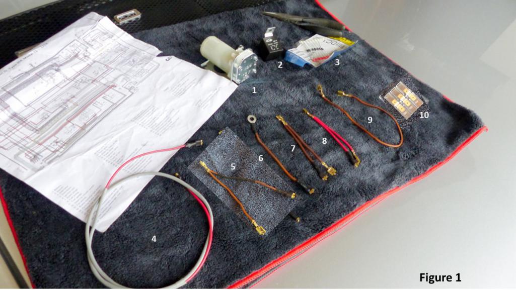 All wires are 18g. I strongly recommend using only automotive grade GXL or TXL wire. This isn’t typically available at your local FLAPS but is easily sourced in many color combinations on ebay. The factory wires are GXL. TXL will be thinner but will work fine. To make black striped wires, I just clamp one end of solid color wire in a vice, pull it taught, and run the side of a sharpie marker along the wire. Part descriptions for Figure 1 are as follows: 1. Windscreen Pump – There are two popular brands that match the OEM pumps used on the 914/6 and 911s of the era. I believe VDO/Continental is the OEM. URO makes a reproduction for about half the price but the one I have makes a loud screaming noise when running. It works fine though as far as I can see but I chose the VDO for my installation. 2. Standard SPST Automotive Relay – You should be able to pick up an RL45 at your local FLAPS for ~$10 or here is a link to an equivalent. 3. 1N4001 Diodes (or equivalent) (2) – These are a very common diode available at Radio Shack or similar. Here is a Digikey Link. If substituting diodes, select diodes with ~1v forward voltage (Vf). This is sometimes also called the “on” voltage. 4. Pump 12v switched power source cable (red/blk) The following only needed if intermittent wiper relay is installed 5. Relay Y-connector Intermittent trigger (Brwn/Blk) with diodes in series 6. Pump ground wire (Brwn) 7. Relay Y-connector ground (Brwn) 8. Relay Y-Connector 12v (Red) 9. Not Used 10. Vintage VW style 3x isolated male connector. You will probably have to buy a 4x connector and cut one of them off to make a 3x. Bug City has them here. Of course you could also do singles but it won’t be as nifty. Installation 1) Install the pump. Refer to SirAndy’s tech article linked above for instructions for installing the pump, rerouting washer hose, and venting the fluid bottle. Note that the VDO and URO pumps have different sized mount openings. The URO will accept an M6 screw or bolt but the VDO has slotted mount points that are smaller (I’m guessing M4). I had already drilled my chassis for a URO pump so I widened the VDO slot with a dremel tool. To ground the pump, crimp a ¼” female spade connector to one end of a short piece of brown wire and a ring terminal appropriately sized for you mounting screw on the other end. Insert the mounting screw through a flat washer, then the ring terminal of the ground wire and through the pump base and chassis. Use a star washer and nut on the cabin side to bite through the paint to create a solid ground. Connect the spade end to the (-) terminal on the pump. Following my OCD for stealth, I vented the fluid bottle cap by running a small drill bit down the existing hole in the cap, then drilled two small holes from the side to create the vent. I also left the hose to the tire attached to give the appearance of the quirky stock mechanism. The hose also makes a nice tether to keep from dropping the bottle cap into the abyss. 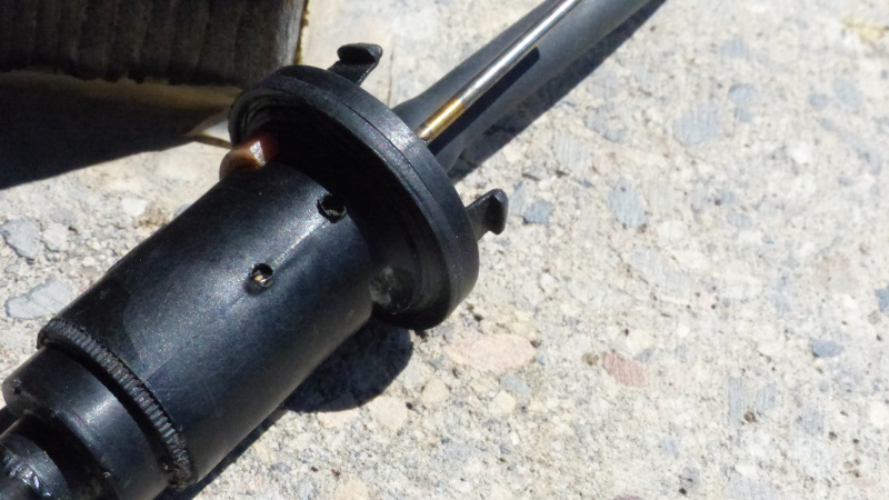 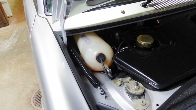 2) Remove charcoal canister (if present) to gain access to intermittent relay and wire location. Installation WITHOUT Intermittent Wiper Delay This differs from the directions in SirAndy’s article because I learned the hard way the switch on the wiper lever is not rated for the ~4 amps needed to run the washer pump. We need to run the pump from a relay (A relay is also usually needed going the microswitch route). Figure 2 shows how the relay is wired. 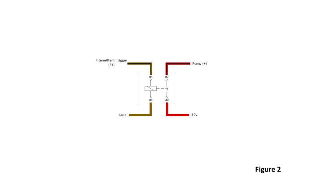 3) Locate the brown/black intermittent wiper delay wire on factory harness. Figure 3 (yellow arrow) shows the wire. If the car never had an intermittent relay, this wire will be folded and wrapped in electrical tape on the factory harness. Refer to SirAndy’s article for pictures. You’ll probably need to unwrap the tape to reveal the wire. 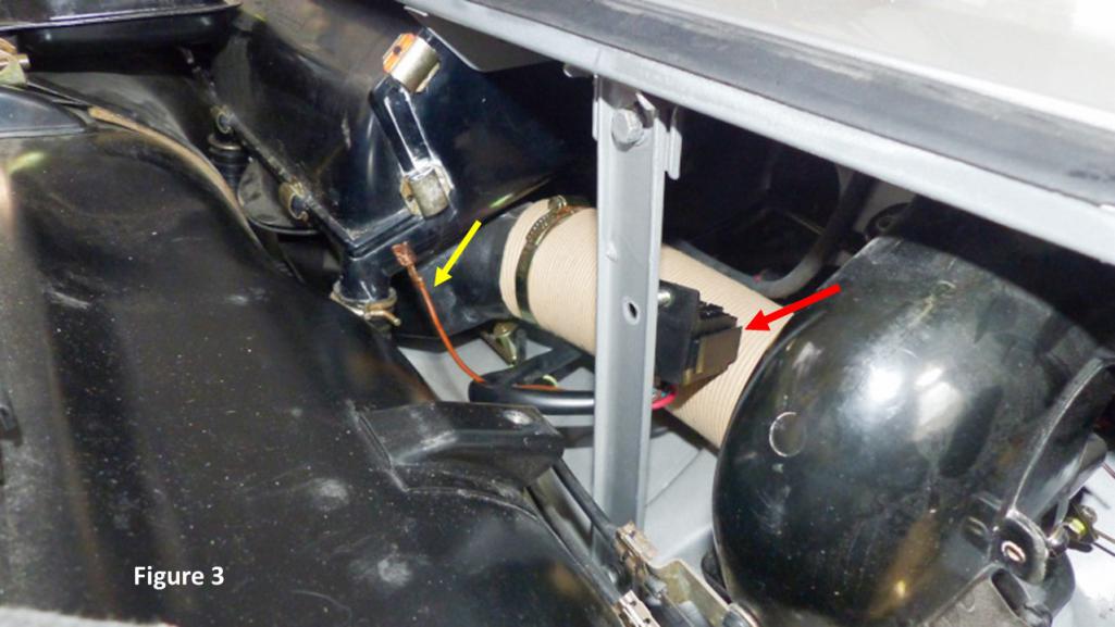 4) Connect the Brwn/Blk wire to terminal 85 on your relay. 5) Connect relay terminal 86 to ground and terminal 30 to 12v power. Here are a couple suggested options for doing this. a. If you have access to the wiper motor wire connections, you can pull 12v power and ground the same as an intermittent delay relay would. Refer to Jeff Bowlsby’s article linked above for details connecting a red and brown wire to the wiper motor the same as you would for adding an intermittent relay. To do this, crimp a dual gender connector to one end of a red, and a brown wire. Cut the wires to length to reach where you will mount the relay (red arrow Figure 3), slide sleeve or shrink wrap over both wires and crimp ¼” female spade connectors on the other ends. 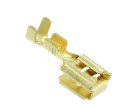 b. Run power (red) wire through the now vacated grommet for the washer hoses into the cabin and connect to the fuse of your choice. Make sure the wire is protected by a fuse. I recommend sleeving the wire and crimp ¼” female spades on each end. Run a ground (brown) wire to the pump (-). Cut a brown wire same length as the pump switched power cable (Figure 1, #4) and crimp a dual gender connector on one end that will connect to the pump. The short pump ground will piggy back off of it. Run the wire through the same sleeve with the pumped switched power wire and add a female spade on the other end. 6) Connect terminal 87 on the relay to one end of the Red/Black wire. Connect the other end (dual gender if you use option “b” above) to pump (+). 7) Attach the relay to the post where an intermittent relay would go using an M6 bolt, split washer and nut. Red arrow on Figure 3 shows an intermittent relay socket. Just put the pump relay there instead. 8) Replace charcoal canister if removed. Congratulations. You’re Done! Installation WITH Intermittent Wiper Delay We need one additional trick to make the washer pump play nice with the wiper delay circuit and the wiring is a little different since we’ll be pulling our connections from the intermittent relay. Figure 4 shows the wiring for the pump relay compatible with the intermittent function. The only difference is the addition of 2 diodes wired in series on the brown/black intermittent trigger wire. 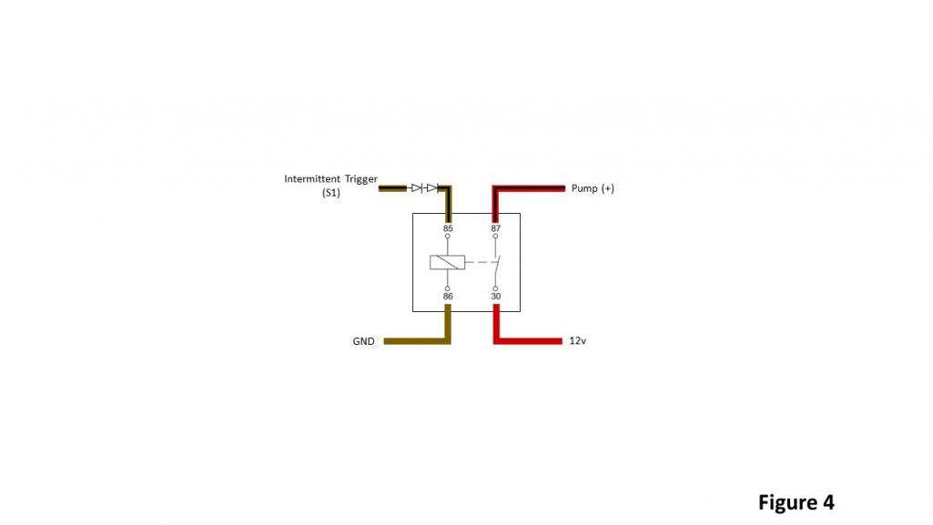 Figure 5 shows the complete wiring diagram. It looks a mess but is really the same as wiring the relay without the intermittent feature except we’ll make 3 Y-harness wires to interconnect between the two relays for the red, brown, and brown/black wires. 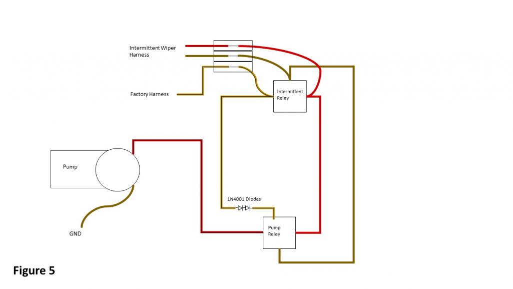 3) Make three Y-harnesses – one each for brown, red, and brown/black. To make the harnesses, cut two same colored pieces of wire about 8” long. Strip one end of each wire, twist them together, and crimp on a ¼” female connector with a locking tab. It is important to use a connector with locking tab so it will snap into the intermittent wiper relay socket. Below is an example of a connector with locking tab. 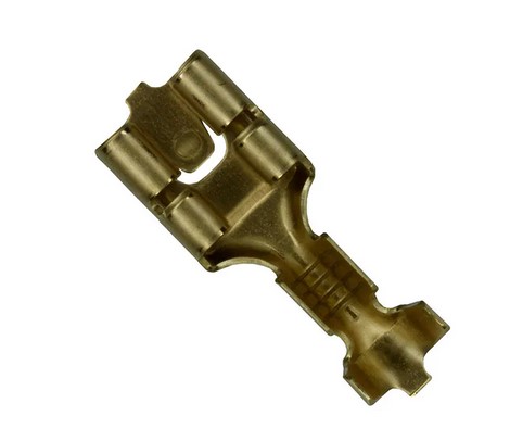 Crimp a regular female connector to each of the remaining ends. Tabbed connectors are fine here too, but not necessary. Leave one end of the Brown/Black Y-harness without a connector for now. 4) Cut the leg of the brown/black Y-harness that does not have a connector in half and solder two diodes in series. It is important that the silver band on one end of the diodes is on the end AWAY from the tabbed connector that forms the Y and toward the free end of the wire. They will be on the side that will connect to the pump relay. If you put a diode in backwards, you will end up scratching your head when nothing works. 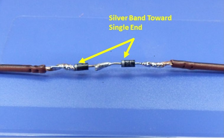 Slide a piece of shrink tubing over the diodes long enough to overlap the insulation on the wire on both ends and heat to shrink. Trim the free end of the wire to match the length of the other side and crimp the remaining female connector on. 5) Now you can start connecting wires at the bench. Connect one free end of the red harness to the middle 3x isolated male connector. Connect one free end of the brown harness to one of the other isolated male connectors on the same side as the red one you just connected. Now connect the free end of the brown/black harness without the diodes to the remaining male connector. Now connect the remaining free ends of the Y-harnesses according to Figure 4. Finally connect the red/black wire from the pump to the relay. 6) Move to the front of the car and start plugging the assembly in. Remove the intermittent relay from its socket. Remove the red wire from the intermittent relay socket by using a small screwdriver or similar from the relay side of the socket to depress the locking tab on the connector and push it out. Once it is out, plug in the red Y-connector in its place and make sure the tab locks in place by tugging backward slightly. Sometimes you have to bend the tab out a little more to get a good lock. Now plug the red wire from the intermittent harness into the other end of the middle 3x connector. Now repeat for the brown and black/brown wires. When all three Y-harnesses are locked into the socket, plug the intermittent harness back in. You have now split the intermittent relay harness so it feeds both relays. 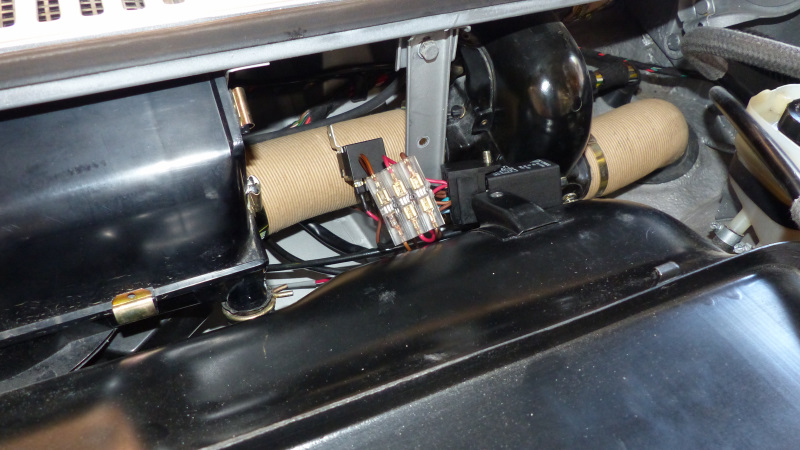 7) Fish the red/black wire to the washer pump. I ran the wire behind the air box along the factory harness, then down and around the front of the right side air diverter valve. There is a vinyl covered bendable harness tab there handy for a neat install. It might take a few tries to get the wire through, but it is stiff enough to push and wiggle through without too much of a fight. Once it is routed, connect it to the (+) terminal on the pump. 8) Time to test things out. You should have four wires connected to the relay and nothing connected to the terminal in the center if there is one. There should be three double wires connected to the intermittent relay. Check to make sure that all ends of the 3x isolated male connector have wires connected and the wire colors match on the ends of each isolated connection. Three wires on one side should go to the intermittent relay. Two wires on the opposite side should connect to the intermittent relay harness. The remaining wire should be connected to the factory harness. Now go inside the car and make sure the wiper switch is in the off position. Turn the key to start position without starting the car. Wait 15 seconds or more and make sure the wipers do not run. Pull back on the wiper lever. You should hear the washer pump run and the wipers will run for 2-4 cycles and stop. Pull the lever down and wait at least 10 seconds. The wipers should run in intermittent mode, cycling once every 10 seconds or so. Finally, move the lever to the slow and fast wiper speed positions to make sure that works. 9) If everything tested ok, you can button things up. If the intermittent relay wasn’t already mounted on the back side of the support bracket, move it there now and push the mounting bolt through the hole to the front. Mount the pump relay on the front of the bracket using the same bolt. Add the lock washer and nut and snug it up. Careful not to drop anything down into the abyss. 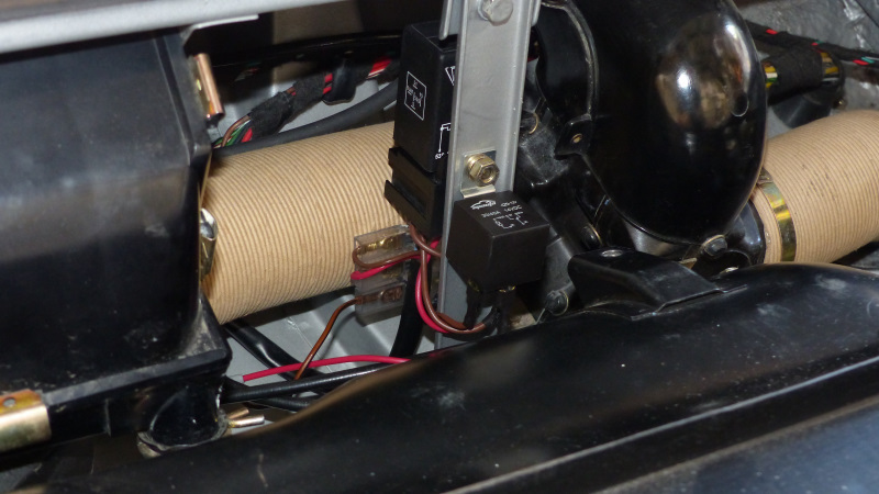 Replace the charcoal canister if present. Have fun with that. Lastly, remount the washer bottle and fill it with you favorite windshield fluid. 10) Finally aim those washer nozzles and… ENJOY! Some Unnecessary, but Fun Background Info on the Circuit Design Theory You may be wondering why the diodes are needed to get the washer pump and intermittent feature to work together. Figuring that out was definitely a group effort, detailed in the thread linked in the intro, and testament to the collective wisdom of 914World. It turns out that mysterious brown/black wire hiding in the factory harness is a bit of a chameleon. It has three different states and jobs depending on the position of the wiper lever. Here’s the schematic for the nerdily curious. 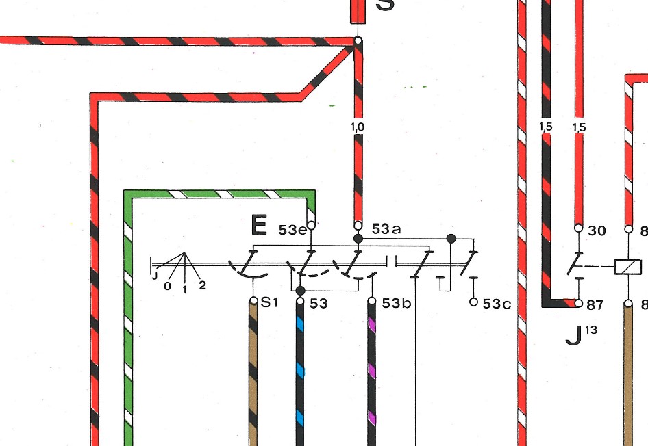 In positions 0-2 (off, slow, and fast), the wire is connected to ground. This prevents the intermittent relay from activating. When the lever is pulled back towards the driver, the wire carries 12v that can be used to power a relay. As mentioned before, the switch isn’t rated for the current needed to run the pump directly. I tried that and after about a week, it quit working. Turns out that the switch was apparently sparking from the amount of current when the washers were activated and built up carbon on the contacts that eventually created enough resistance that the pump would no longer run. Hence, the relay. Finally, when the wiper lever is pulled down, the black/brown wire is completely disconnected from power or ground. This allows the intermittent relay to activate. When that wire is connected to a motor or relay coil, enough current (just a few millivolts) leaks to ground even when the lever is in the down position that the intermittent feature never turns on. The challenge is to create a circuit that lets 12v flow to the relay when the lever is pulled back, but is electrically isolated when the lever is pulled down. The “brain trust” suggested a diode might work which confused me at first. If you don’t know, a diode is a semiconductor that allows current to flow in only one direction – an electrical check valve. It didn’t make sense how that would solve the problem until I learned that diodes need a certain forward (or “on”) voltage (Vf) to get the current flowing. Since the voltage of the leak through the relay was small, that Vf might just be enough to isolate the circuit from ground when the wiper lever is pulled down. I tried it and the intermittent wipers still wouldn’t run, but the relay would chatter which indicated I was getting close. Adding a second diode to increase the total Vf to isolate the ground enough to activate the relay did the trick. Thus, the 3-state chameleon properties of the wire was restored despite being connected to a leaky relay. |
| SirAndy |
 Aug 16 2022, 09:53 AM Aug 16 2022, 09:53 AM
Post
#2
|
|
Resident German                          Group: Admin Posts: 42,378 Joined: 21-January 03 From: Oakland, Kalifornia Member No.: 179 Region Association: Northern California |
(IMG:style_emoticons/default/smilie_pokal.gif)
I should probably update that tech article ... (IMG:style_emoticons/default/biggrin.gif) PS: I added a link to this thread to the classics section Lapuwali Classic Thread Forum . |
| bbrock |
 Aug 16 2022, 01:02 PM Aug 16 2022, 01:02 PM
Post
#3
|
|
914 Guru      Group: Members Posts: 5,269 Joined: 17-February 17 From: Montana Member No.: 20,845 Region Association: Rocky Mountains 
|
(IMG:style_emoticons/default/smilie_pokal.gif) I should probably update that tech article ... (IMG:style_emoticons/default/biggrin.gif) PS: I added a link to this thread to the classics section Lapuwali Classic Thread Forum Sweet! My long time dream making to the Lapuwali Classics now a reality. Thanks! (IMG:style_emoticons/default/beerchug.gif) |
| DRPHIL914 |
 Aug 16 2022, 01:03 PM Aug 16 2022, 01:03 PM
Post
#4
|
|
Dr. Phil      Group: Members Posts: 5,875 Joined: 9-December 09 From: Bluffton, SC Member No.: 11,106 Region Association: South East States 
|
Nicely done!! i did the Car Magic switch and install of a NOS porsche pump from 914Sixer.
it works great, i did this when i had the column apart for putting in new signal lever etc too. good to know there is more than one way to do it. Phil |
| NARP74 |
 Aug 16 2022, 01:27 PM Aug 16 2022, 01:27 PM
Post
#5
|
|
Senior Member    Group: Members Posts: 1,446 Joined: 29-July 20 From: Colorado, USA, Earth Member No.: 24,549 Region Association: Rocky Mountains |
This is great work.
OCD at wiring, you're hired! I can get the job working but I'm crap at making it look clean. Come by anytime... |
| autopro |
 Aug 16 2022, 01:30 PM Aug 16 2022, 01:30 PM
Post
#6
|
|
Member   Group: Members Posts: 306 Joined: 14-January 18 From: San Diego / Tijuana Member No.: 21,797 Region Association: Southern California |
I just did mine with the aftermarket switch but I would have loved to do it this way. Great writeup and thanks for sharing (IMG:style_emoticons/default/beerchug.gif)
|
| Literati914 |
 Aug 16 2022, 08:34 PM Aug 16 2022, 08:34 PM
Post
#7
|
|
Advanced Member     Group: Members Posts: 2,177 Joined: 16-November 06 From: Dallas, TX Member No.: 7,222 Region Association: Southwest Region |
|
| Eric_Shea |
 May 1 2023, 04:36 PM May 1 2023, 04:36 PM
Post
#8
|
|
PMB Performance                Group: Admin Posts: 19,304 Joined: 3-September 03 From: Salt Lake City, UT Member No.: 1,110 Region Association: Rocky Mountains  |
Phenomenal write up Brent (IMG:style_emoticons/default/smilie_pokal.gif) (IMG:style_emoticons/default/smilie_pokal.gif) (IMG:style_emoticons/default/smilie_pokal.gif)
|
| FlacaProductions |
 May 1 2023, 07:19 PM May 1 2023, 07:19 PM
Post
#9
|
|
Advanced Member     Group: Members Posts: 2,108 Joined: 24-November 17 From: LA Member No.: 21,628 Region Association: Southern California 
|
Has anyone heard from Brent lately? I see he hasn't logged in since 31st March 2023 - @bbrock - you out there?
|
| jim_hoyland |
 Sep 3 2025, 07:08 PM Sep 3 2025, 07:08 PM
Post
#10
|
|
Get that VIN ?      Group: Members Posts: 9,964 Joined: 1-May 03 From: Sunset Beach, CA Member No.: 643 Region Association: Southern California 
|
Great write up showing details of wiring the wiper switch to a water pump. Just used the info to trouble shoot a glitch…. (IMG:style_emoticons/default/smile.gif)
@bbrock |
| mepstein |
 Sep 4 2025, 04:01 AM Sep 4 2025, 04:01 AM
Post
#11
|
|
914-6 GT in waiting                Group: Members Posts: 20,299 Joined: 19-September 09 From: Landenberg, PA/Wilmington, DE Member No.: 10,825 Region Association: MidAtlantic Region 
|
Great write up showing details of wiring the wiper switch to a water pump. Just used the info to trouble shoot a glitch…. (IMG:style_emoticons/default/smile.gif) @bbrock We miss him. (IMG:style_emoticons/default/sad.gif) |
| FlacaProductions |
 Sep 4 2025, 07:30 AM Sep 4 2025, 07:30 AM
Post
#12
|
|
Advanced Member     Group: Members Posts: 2,108 Joined: 24-November 17 From: LA Member No.: 21,628 Region Association: Southern California 
|
|
| Dion |
 Sep 5 2025, 09:38 PM Sep 5 2025, 09:38 PM
Post
#13
|
|
RN     Group: Members Posts: 2,920 Joined: 16-September 04 From: Audubon,PA Member No.: 2,766 Region Association: MidAtlantic Region 

|
This forum has not been the same without him.
Definitely miss him. |
  |
2 User(s) are reading this topic (2 Guests and 0 Anonymous Users)
0 Members:

|
Lo-Fi Version | Time is now: 22nd December 2025 - 06:38 AM |
Invision Power Board
v9.1.4 © 2025 IPS, Inc.


