|
|
|
Porsche, and the Porsche crest are registered trademarks of Dr. Ing. h.c. F. Porsche AG.
This site is not affiliated with Porsche in any way. Its only purpose is to provide an online forum for car enthusiasts. All other trademarks are property of their respective owners. |
|
|

  |

| technicalninja |
 Jul 26 2024, 07:59 PM Jul 26 2024, 07:59 PM
Post
#41
|
|
Senior Member  Group: Members Posts: 1,821 Joined: 31-January 23 From: Granbury Texas Member No.: 27,135 Region Association: Southwest Region |
A few times in that vid you can see big ass holes (3/4"?) in the "oil towers" on all of the cases.
He doesn't say shit about them. I'm thinking crankcase ventilation but. "Inquiring minds want to know..." What do you think @Superhawk996 |
   |

 
|
| Superhawk996 |
Jul 26 2024, 09:26 PM
Post
#42
|
|
914 Guru Group: Members Posts: 6,464 Joined: 25-August 18 From: Woods of N. Idaho Member No.: 22,428 Region Association: Galt's Gulch |
QUOTE(technicalninja @ Jul 26 2024, 09:59 PM)  A few times in that vid you can see big ass holes (3/4"?) in the "oil towers" on all of the cases. He doesn't say shit about them. I'm thinking crankcase ventilation but. "Inquiring minds want to know..." What do you think @Superhawk996 I don’t know for sure. I don’t think I see that on all three cases but maybe didn’t watch close enough. I do know that HAM and RAT did some work to determine what really was needed for optimal case breathing but it isn’t entirely clear where they vented the 3/4” breather. It seems this was also focused more on racing and potentially on a dry sump oiling system so (IMG:style_emoticons/default/confused24.gif) Seems like they said that for typical road use with wet sump, a more conventional breather can is sufficient. I’ve always built close to stock engines so I’ve never had breather issues. Link to HAM/RAT breather study http://newsite.hamheads.com/2016/12/10/typ...tests-analysis/ |
 |
|
| 914werke |
Jul 26 2024, 09:37 PM
Post
#43
|
|
"I got blisters on me fingers" Group: Members Posts: 10,490 Joined: 22-March 03 From: USofA Member No.: 453 Region Association: Pacific Northwest |
7:38 you can see 2 holes on the L. side of the fill tower. 1 above & 1 below the tin sealing shelf. The one below is closer to 1". (IMG:style_emoticons/default/idea.gif)
|
|
|
|
| Jack Standz |
Jul 26 2024, 09:44 PM
Post
#44
|
|
Member Group: Members Posts: 361 Joined: 15-November 19 From: Happy Place (& surrounding area) Member No.: 23,644 Region Association: None |
QUOTE(Robroe @ Jul 27 2024, 07:57 AM) QUOTE(Superhawk996 @ Jul 26 2024, 12:13 PM) From pictures I’m don’t think I see the Raby Rear Main Seal drain back modification . I’d do that while case is split. Can you point me to Rabys Rear Main Seal drain back modification? Tried searching but haven’t found anything except reference to it, not what it is or how to do it. Thanks! Yes, I was thinking about this question and came back to ask. But you beat me to it. Some of us are visual people. Anyone have a photo of this modification they could share? Maybe with some measurements too? The video isn't easy to see things. Maybe a better screen would help, but a few good photos are better. I looked at Bob Burton's friend's rebuild. But, it seems his was built before this modification was being used at RAT. We have a motor we're planning & rather than take a guess at how to make this modification, it'd be really helpful to see how others have done it. On a related point, does anyone have photos of a roller cammed Type IV? We have Type 1 tool steel lifters that we plan to use with modified lifter bores on the next motor build. However, the roller cam has benefits over solid cams. Any help with getting a roller lifter/cam setup that you could share would really help the 914 community. Thx |
|
|
|
| Robroe |
Jul 26 2024, 09:49 PM
Post
#45
|
|
Member Group: Members Posts: 76 Joined: 10-August 21 From: Wenatchee, WA Member No.: 25,793 Region Association: Pacific Northwest |
QUOTE(Superhawk996 @ Jul 26 2024, 08:54 PM) He discusses it further at 11:55 mark Thank you! |
|
|
|
| Jack Standz |
Jul 26 2024, 09:50 PM
Post
#46
|
|
Member Group: Members Posts: 361 Joined: 15-November 19 From: Happy Place (& surrounding area) Member No.: 23,644 Region Association: None |
QUOTE(technicalninja @ Jul 27 2024, 08:59 AM) A few times in that vid you can see big ass holes (3/4"?) in the "oil towers" on all of the cases. He doesn't say shit about them. I'm thinking crankcase ventilation but. "Inquiring minds want to know..." What do you think @Superhawk996 Agree with you. They are probably crankcase ventilation. We're running only an -AN 12 line from the oil tower to a catch can with no vents at the valve covers in a 2056 with no problems so far. Didn't we have this conversation before? (IMG:style_emoticons/default/smile.gif) |
|
|
|
| technicalninja |
Jul 26 2024, 10:00 PM
Post
#47
|
|
Senior Member Group: Members Posts: 1,821 Joined: 31-January 23 From: Granbury Texas Member No.: 27,135 Region Association: Southwest Region |
OK, that was weird...
Got a message that that link was current under attack/taken over and my security suite wouldn't let me connect. It also said this type of trouble was usually temporary and the site would work properly later. I've never hit that before??? I believe Raby gathers crankcase pressure data a bunch. I've seen multiple posts from him mentioning it. He uses it to judge ring sealing performance mostly (I think). Dry sump usually SOLVES all of your crankcase pressure issues. Most of the systems I've messed with have dedicated vacuum relief valves to NOT allow too low an internal engine pressure. If I'm remembering properly those valves have "low" settings. They vent at 3-5" of vacuum. I haven't messed with OEM dry sump at all with the exception of 911 stuff. Most of "my" cars didn't rate dry sump from the get-go. |
|
|
|
| technicalninja |
Jul 26 2024, 10:25 PM
Post
#48
|
|
Senior Member Group: Members Posts: 1,821 Joined: 31-January 23 From: Granbury Texas Member No.: 27,135 Region Association: Southwest Region |
QUOTE(Jack Standz @ Jul 26 2024, 10:44 PM) QUOTE(Robroe @ Jul 27 2024, 07:57 AM) QUOTE(Superhawk996 @ Jul 26 2024, 12:13 PM) From pictures I’m don’t think I see the Raby Rear Main Seal drain back modification . I’d do that while case is split. Can you point me to Rabys Rear Main Seal drain back modification? Tried searching but haven’t found anything except reference to it, not what it is or how to do it. Thanks! Yes, I was thinking about this question and came back to ask. But you beat me to it. Some of us are visual people. Anyone have a photo of this modification they could share? Maybe with some measurements too? The video isn't easy to see things. Maybe a better screen would help, but a few good photos are better. I looked at Bob Burton's friend's rebuild. But, it seems his was built before this modification was being used at RAT. We have a motor we're planning & rather than take a guess at how to make this modification, it'd be really helpful to see how others have done it. On a related point, does anyone have photos of a roller cammed Type IV? We have Type 1 tool steel lifters that we plan to use with modified lifter bores on the next motor build. However, the roller cam has benefits over solid cams. Any help with getting a roller lifter/cam setup that you could share would really help the 914 community. Thx I was going down this road as well... I'm a full roller, VVT, 4 valve, DI, variable intake, DOHC, VATN turbo with two stage intercooler type of guy. When you just say "Fuch it" and drop the WHOLE Type 4 idea EVERYTHING gets so much easier... And a SHITLOAD cheaper! The only way I'll build a Type4 is if I luck into exactly what the OP has. That's what has made this thread interesting for me. Be careful with saying rollers are better. They are different. Up to 230@.050 flats are usually FASTER at opening the valves off of the seats. Rollers open slowly... Rollers can run steeper ramps and are better for large lift/duration but anything below those numbers the flats will work better. The cost of creating roller lifters for a type 4 vastly exceeds the value they will provide the engine IMO. How much MORE power do you think they will make? 10% would be a shitload IMO. So, 20-30 HP for how much money? Raby bought up ALL of the oversize ceramic lifter stock on the market. I think he's big into ceramics now. He mentioned rollers at one time on one of his pages. 8K was the cost... I can buy 2 used Bentley W12 twin turbo motors with all of the garbage on them for that type of money. I can buy a 4-mile LGX GM V6 for 3K if I want. Used ones can be had for 1K. I actually want one of those... (IMG:style_emoticons/default/devil.gif) |
|
|
|
| Robroe |
Jul 27 2024, 12:40 AM
Post
#49
|
|
Member Group: Members Posts: 76 Joined: 10-August 21 From: Wenatchee, WA Member No.: 25,793 Region Association: Pacific Northwest |
QUOTE(Superhawk996 @ Jul 26 2024, 08:54 PM) He discusses it further at 11:55 mark He skims over it pretty quick. Any other photos and examples you know about? Not sure I want to file or machine my case unless I’m positive of the process. |
|
|
|
| Superhawk996 |
Jul 27 2024, 07:39 AM
Post
#50
|
|
914 Guru Group: Members Posts: 6,464 Joined: 25-August 18 From: Woods of N. Idaho Member No.: 22,428 Region Association: Galt's Gulch |
It’s just another oil drain back passage at a lower point 6 o’clock position rather than the OEM oil drain to prevent oil from pooling up behind the RMS. As ninja stated, the 12 o’clock position is an air breather to enhance drainback.
It can be be done easily with a mill by a competent machinist. Hand filing it will take a little while but isn’t out of the question. If it’s not for you, that’s OK too. It’s just a mod to help reduce the tendency for RMS to leak. It goes right along with the risk of having an RMS fail because it was pounded in with a hammer and having the garter spring pop off the seal vs. pressing the seal in using a press tool that seats the RMS slowly and uniformly. Shade trees have been banging seals in with a hammer for decades. There are also a lot of RMS leakers out there. Personally, I do everything I can to avoid RMS leaks since they aren’t fun to fix and are so messy. 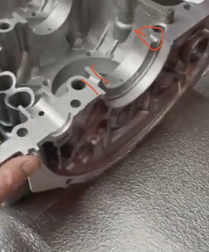 |
|
|
|
| technicalninja |
Jul 27 2024, 09:41 AM
Post
#51
|
|
Senior Member Group: Members Posts: 1,821 Joined: 31-January 23 From: Granbury Texas Member No.: 27,135 Region Association: Southwest Region |
What I haven't see yet is "what does the other case side look like?"
Does Raby do the groove on both cases? I don't know! The groove is pretty big as is. If that was the only thing the case needs, I'd do that mod by hand with a triangle file. There's another "gotcha" out there as well... Lots of folks have posted about the quality of the current crop of RMS. Common gripes are "The molds are old, and the seals are less likely to work." I haven't seen "Use this brand and you'll be OK" yet... So, if I was trying to make a RMS work in a T4 today I'd be looking for NOS old shit. You've already seen one super nice thing about SH... I posted the video, but he posted "best time to look" is 11:55. He can be far more precise than me about exactly what to look at. Saves TIME! Now the whole video is worth watching a few times. When I went back and checked 11:55 I saw something I missed the first time around. I have late cases and the video states late cases need bigger groves!!! Not sure how I missed that but thanks @Superhawk996 (IMG:style_emoticons/default/first.gif) I'm also in agreement about the need to have the RMS seal. It's SO messy and requires a full-on clutch job to do. I'll go to great lengths to miss that opportunity for "Practice bleeding". "Practice bleeding" is any job you get to do twice because you were a moron the first time around! I've done it far too often... |
|
|
|
| Superhawk996 |
Jul 27 2024, 02:12 PM
Post
#52
|
|
914 Guru Group: Members Posts: 6,464 Joined: 25-August 18 From: Woods of N. Idaho Member No.: 22,428 Region Association: Galt's Gulch |
QUOTE(technicalninja @ Jul 27 2024, 11:41 AM) What I haven't see yet is "what does the other case side look like?" Does Raby do the groove on both cases? I don't know! No. In the video the groove is only in one side only (mating side from video below) I suspect it isn’t hugely critical. My guess is that it’s only in one side because . . . Why set up in the mill twice and go to the trouble to match the position between case halves. Just trying to get a lower alternative path to bleed out some additional oil below the OEM drain. 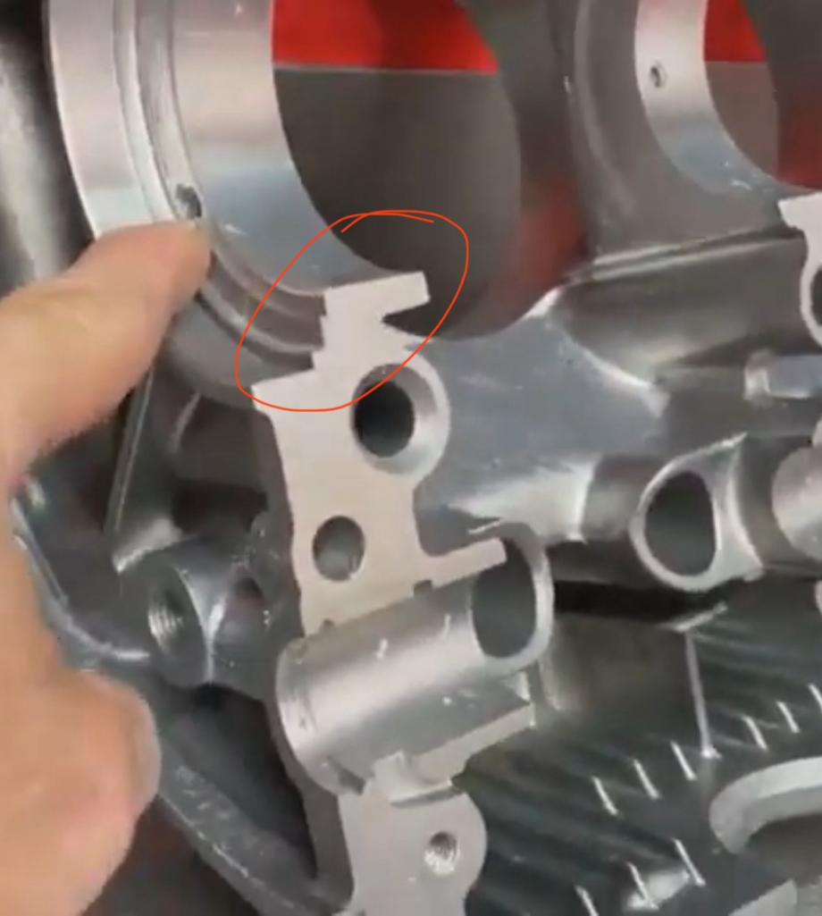 |
|
|
|
| technicalninja |
Jul 27 2024, 02:17 PM
Post
#53
|
|
Senior Member Group: Members Posts: 1,821 Joined: 31-January 23 From: Granbury Texas Member No.: 27,135 Region Association: Southwest Region |
Yep! You're right.
I should have caught that! Bad ninja, bad, bad ninja... (IMG:style_emoticons/default/ninja.gif) |
|
|
|
| Robroe |
Jul 27 2024, 03:01 PM
Post
#54
|
|
Member Group: Members Posts: 76 Joined: 10-August 21 From: Wenatchee, WA Member No.: 25,793 Region Association: Pacific Northwest |
QUOTE(Superhawk996 @ Jul 27 2024, 03:12 PM) QUOTE(technicalninja @ Jul 27 2024, 11:41 AM) What I haven't see yet is "what does the other case side look like?" Does Raby do the groove on both cases? I don't know! No. In the video the groove is only in one side only (mating side from video below) I suspect it isn’t hugely critical. My guess is that it’s only in one side because . . . Why set up in the mill twice and go to the trouble to match the position between case halves. Just trying to get a lower alternative path to bleed out some additional oil below the OEM drain. Here are close up picts of the RMS and Rear main bearing test installed to get a better understanding of the RMS leak back mod to avoid oil trapped too high behind the seal causing RMS leaks. Please see my feeble attempt at drawing a line where the groove is cut in the lower case. With the RMS and bearing installed, you can see the proper place to cut the groove between the seal and bearing on either side of the RMS. I heard .060" for width and depth. Is that correct? Should I really do it myself with a triangle file or a Dremel? Or should I ask the local small town 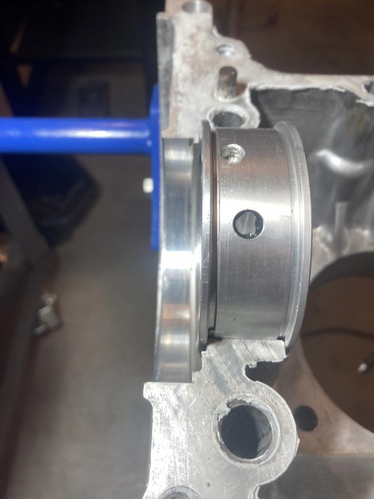 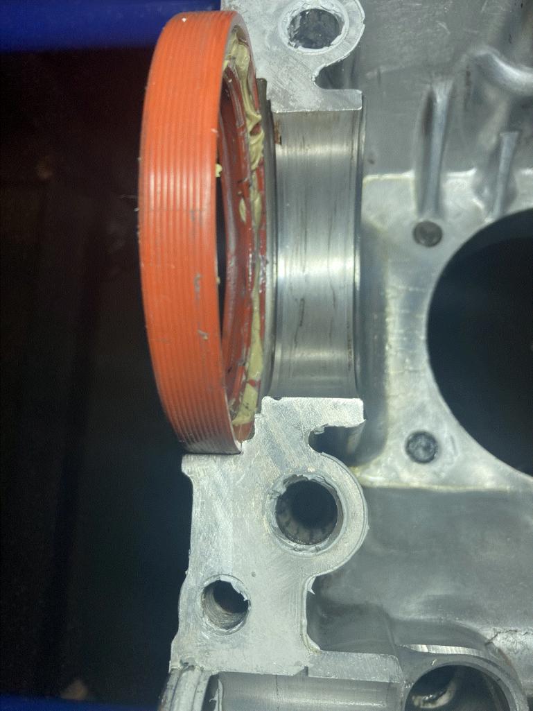 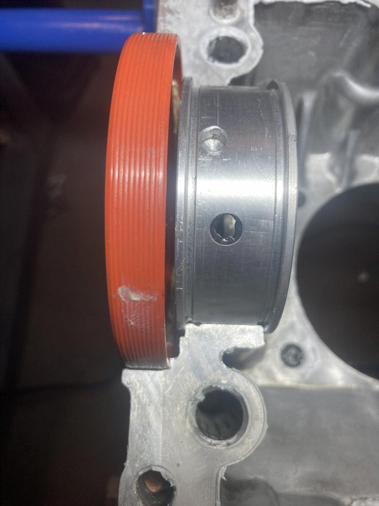 [attachmentid [attachmentid=917843] 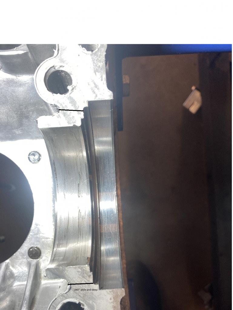 machine shop to cut it more precisely than I could. Thanks very much! Starting to get to know you guys and definitely appreciate and depend on your input. Thanks! machine shop to cut it more precisely than I could. Thanks very much! Starting to get to know you guys and definitely appreciate and depend on your input. Thanks!Attached thumbnail(s) 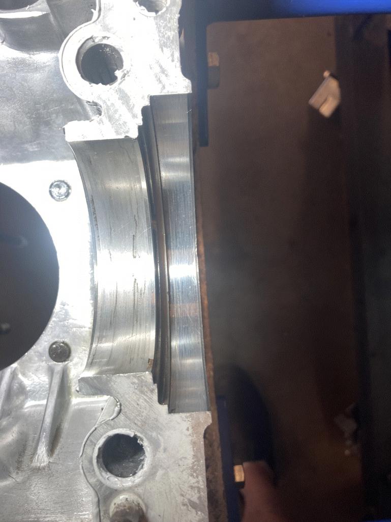
|
|
|
|
| technicalninja |
Jul 27 2024, 03:07 PM
Post
#55
|
|
Senior Member Group: Members Posts: 1,821 Joined: 31-January 23 From: Granbury Texas Member No.: 27,135 Region Association: Southwest Region |
Your marked lines are perfect!
I'd use a flat filing technique and a triangle file. Less than 5 minutes is what I'd expect... You don't have to be "Ninja exact" here. File that puppy till it looks like Jake's Video and be done with it... Biggest thing is to stay in your grove and don't mark/nick the case up much. A little scratch here and there shouldn't create a problem however... |
|
|
|
| 914werke |
Jul 27 2024, 03:17 PM
Post
#56
|
|
"I got blisters on me fingers" Group: Members Posts: 10,490 Joined: 22-March 03 From: USofA Member No.: 453 Region Association: Pacific Northwest |
|
|
|
|
| Jack Standz |
Jul 27 2024, 03:40 PM
Post
#57
|
|
Member Group: Members Posts: 361 Joined: 15-November 19 From: Happy Place (& surrounding area) Member No.: 23,644 Region Association: None |
Thanks everyone.
Don't have a mill. With the right bit, I'm putting my $ on using a small router, like for drywall installation, to do it. Have a couple routers with multiple bits. The groove is not really critical anyway., other than location. |
|
|
|
| Jack Standz |
Jul 27 2024, 04:08 PM
Post
#58
|
|
Member Group: Members Posts: 361 Joined: 15-November 19 From: Happy Place (& surrounding area) Member No.: 23,644 Region Association: None |
QUOTE(technicalninja @ Jul 27 2024, 11:25 AM) QUOTE(Jack Standz @ Jul 26 2024, 10:44 PM) QUOTE(Robroe @ Jul 27 2024, 07:57 AM) QUOTE(Superhawk996 @ Jul 26 2024, 12:13 PM) From pictures I’m don’t think I see the Raby Rear Main Seal drain back modification . I’d do that while case is split. Can you point me to Rabys Rear Main Seal drain back modification? Tried searching but haven’t found anything except reference to it, not what it is or how to do it. Thanks! Yes, I was thinking about this question and came back to ask. But you beat me to it. Some of us are visual people. Anyone have a photo of this modification they could share? Maybe with some measurements too? The video isn't easy to see things. Maybe a better screen would help, but a few good photos are better. I looked at Bob Burton's friend's rebuild. But, it seems his was built before this modification was being used at RAT. We have a motor we're planning & rather than take a guess at how to make this modification, it'd be really helpful to see how others have done it. On a related point, does anyone have photos of a roller cammed Type IV? We have Type 1 tool steel lifters that we plan to use with modified lifter bores on the next motor build. However, the roller cam has benefits over solid cams. Any help with getting a roller lifter/cam setup that you could share would really help the 914 community. Thx I was going down this road as well... I'm a full roller, VVT, 4 valve, DI, variable intake, DOHC, VATN turbo with two stage intercooler type of guy. When you just say "Fuch it" and drop the WHOLE Type 4 idea EVERYTHING gets so much easier... And a SHITLOAD cheaper! The only way I'll build a Type4 is if I luck into exactly what the OP has. That's what has made this thread interesting for me. Be careful with saying rollers are better. They are different. Up to 230@.050 flats are usually FASTER at opening the valves off of the seats. Rollers open slowly... Rollers can run steeper ramps and are better for large lift/duration but anything below those numbers the flats will work better. The cost of creating roller lifters for a type 4 vastly exceeds the value they will provide the engine IMO. How much MORE power do you think they will make? 10% would be a shitload IMO. So, 20-30 HP for how much money? Raby bought up ALL of the oversize ceramic lifter stock on the market. I think he's big into ceramics now. He mentioned rollers at one time on one of his pages. 8K was the cost... I can buy 2 used Bentley W12 twin turbo motors with all of the garbage on them for that type of money. I can buy a 4-mile LGX GM V6 for 3K if I want. Used ones can be had for 1K. I actually want one of those... (IMG:style_emoticons/default/devil.gif) Yeah, I'm with you. If we were going with a water pumper in a 914, I'd seriously think about a quad cam 32 valve 928 motor (actually have one in the garage) or a Cayenne V8. Kinda like the alien. Because, why not? But, we aren't going that route. We like air-cooled. Just like the idea of a roller cammed Type IV motor. Didn't say it was better, but it does have benefits. Less friction, lower spring pressure while potentially higher rpms before valve float, potentially better spring control (maybe run behive springs), faster more aggressive ramps on the lobes (getting custom cams and all the development over multiple iterations needed is really the area likely to kill the dream), etc. Wasn't thinking you'd have to create roller lifters for a Type IV. Just find existing ones (Ford?) and make the lifter bores & bosses work with them. Probably solid roller lifters, but maybe hydraulic would work. Benefit is no valve adjustments. Again, you get back to developing a custom cam that works. That would be expensive and time consuming. |
|
|
|
| Jack Standz |
Jul 27 2024, 04:26 PM
Post
#59
|
|
Member Group: Members Posts: 361 Joined: 15-November 19 From: Happy Place (& surrounding area) Member No.: 23,644 Region Association: None |
QUOTE(Superhawk996 @ Jul 27 2024, 08:39 PM) It’s just another oil drain back passage at a lower point 6 o’clock position rather than the OEM oil drain to prevent oil from pooling up behind the RMS. As ninja stated, the 12 o’clock position is an air breather to enhance drainback. It can be be done easily with a mill by a competent machinist. Hand filing it will take a little while but isn’t out of the question. If it’s not for you, that’s OK too. It’s just a mod to help reduce the tendency for RMS to leak. It goes right along with the risk of having an RMS fail because it was pounded in with a hammer and having the garter spring pop off the seal vs. pressing the seal in using a press tool that seats the RMS slowly and uniformly. Shade trees have been banging seals in with a hammer for decades. There are also a lot of RMS leakers out there. Personally, I do everything I can to avoid RMS leaks since they aren’t fun to fix and are so messy. +1 thanks for the photo. Have the RMS seal installation tool. No more pounding it in with a rubber or steel hammer. |
|
|
|
| Robroe |
Jul 27 2024, 04:30 PM
Post
#60
|
|
Member Group: Members Posts: 76 Joined: 10-August 21 From: Wenatchee, WA Member No.: 25,793 Region Association: Pacific Northwest |
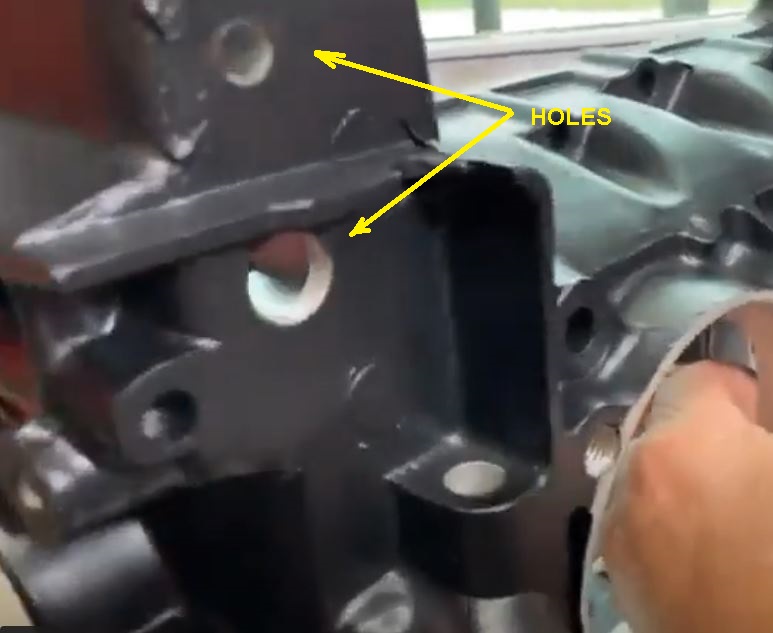
QUOTE(914werke @ Jul 27 2024, 04:17 PM) 914Werke - can a newbie ask a dumb question? What do the holes shown in your photo do? Does this have something to do with RMS leak prevention? |
|
|
|
|
1 User(s) are reading this topic (1 Guests and 0 Anonymous Users)
0 Members:

|
Lo-Fi Version | Time is now: 16th September 2024 - 12:49 PM |
Invision Power Board
v9.1.4 © 2024 IPS, Inc.