|
|
|
Porsche, and the Porsche crest are registered trademarks of Dr. Ing. h.c. F. Porsche AG.
This site is not affiliated with Porsche in any way. Its only purpose is to provide an online forum for car enthusiasts. All other trademarks are property of their respective owners. |
|
|

  |

| technicalninja |
 Jul 27 2024, 07:32 PM Jul 27 2024, 07:32 PM
Post
#61
|
|
Senior Member  Group: Members Posts: 1,821 Joined: 31-January 23 From: Granbury Texas Member No.: 27,135 Region Association: Southwest Region |
That pic is from the Jake's crankcase video.
914werke was pointing out that there are two holes in the oil tower (my name for that part of the casting, might be mis-named, I'm weird!). We all have questions as to what it does and why two holes are needed. The most obvious reason is for crankcase ventilation. Jake can be secretive and didn't mention them. A vent already exists in this area, and it seems redundant to many of us to add more. Crankcase ventilation is CRITICAL for multiple reasons but one of them is oil leaks. If a crankcase is completely sealed it will quickly gain internal pressure from blow by gasses (all engines have some) and heat. One path for this excessive pressure is through any seals/gaskets on the engine. They blow outward... Modern engines are scavenged by the PCV system, and the "normal" method is to create a metered flow into the intake manifold. The engine SUCKS itself! (IMG:style_emoticons/default/happy11.gif) Dry sump engines have enough suction from the scavenge section of the pump that they can pull a vacuum to the point of gasket and seal failure as well. In this scenario the seals/gaskets fail inward. Hence my comment of vacuum release valves in a previous post. So, the answer to your question is Yes, this has bearing on seal/gasket life, but it is not DIRECTLY for RMS improvements alone. We would all like to see how Jake has those holes plumbed. What are they hooked up too? The really important question is why did he do it this way? He always has reasons and the level of experience he has makes him "Top Dog" to many of us. Knowing the WHY allows us to apply similar techniques to other builds. Might not be German at all. Most of us (the gear heads) are as interested in the "Journey" as the end result because we know this is NOT the only "Journey" we will travel... I'm no longer planning on taking a T4 journey. I've gone modern. Even still it's interesting enough for me to take the time to post in this thread. Now, if I had your engine, I would change my plans... You got SO LUCKY! It could be better, it could be an entire RAT, but what you have there already is what I consider the bottom of the APEX engine scale regarding T4s... Almost everyone could make 150 hp with that. Someone really good might clear 175. That LGX I mentioned makes 335 stock with a restrictive exhaust, intake, and a tune more interested in emissions over power... Now, the LGX means the ENTIRE car requires mods, almost nothing stock is applicable. It is a HUGE undertaking, a journey fit for a Ninja. (IMG:style_emoticons/default/ninja.gif) Your kitten could fit right into a stock car... |
   |

 
|
| Robroe |
Jul 28 2024, 03:59 PM
Post
#62
|
|
Member Group: Members Posts: 76 Joined: 10-August 21 From: Wenatchee, WA Member No.: 25,793 Region Association: Pacific Northwest |
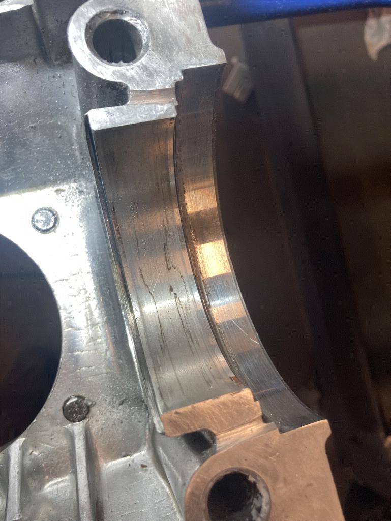
Picture of the grooves to drain pooled oil behind rear main seal into crankcase faster. Just used a .10" thick flat file on its edge. Then added a little channel at the bottom of the groove using a triangle file. Now off to machine shop for cleaning block halves and cylinders in cleaning tank.
 |
|
|
|
| Robroe |
Jul 28 2024, 04:13 PM
Post
#63
|
|
Member Group: Members Posts: 76 Joined: 10-August 21 From: Wenatchee, WA Member No.: 25,793 Region Association: Pacific Northwest |
Crankshaft end play dilema. When assembled, the crank end play was .045" not .004". Did a mock up of crank in bottom half of case with bearings to see if I could learn anything. The most repeatable end play measurement was .058". I understand this is just a mock up rough measurement, but so far off that I'm concerned about it. The end play shims I have are .0013, .0015 and .0015. Of course these won't fill the .045" gap when assembled.
Here's my question. Since the shims rest against the outside of the rear main bearing (thrust bearing), could the rear main thrust bearing lip be too narrow? Here are picts of the mock up and bearing. If so, how would one order the proper thrust bearing lip size? 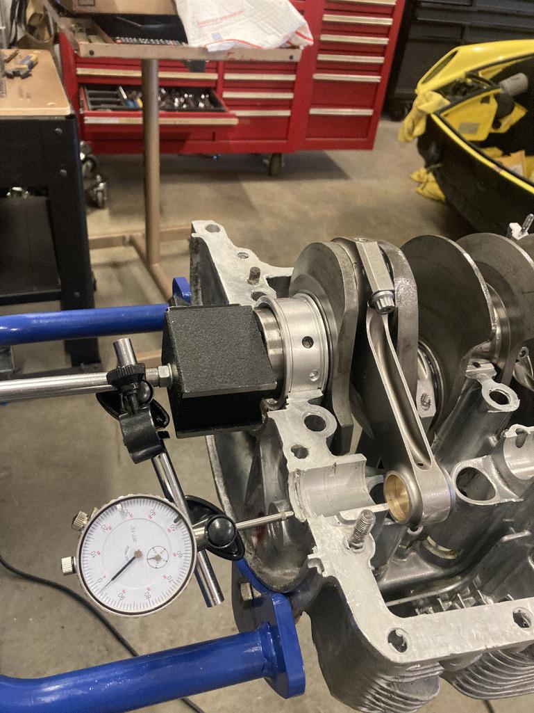 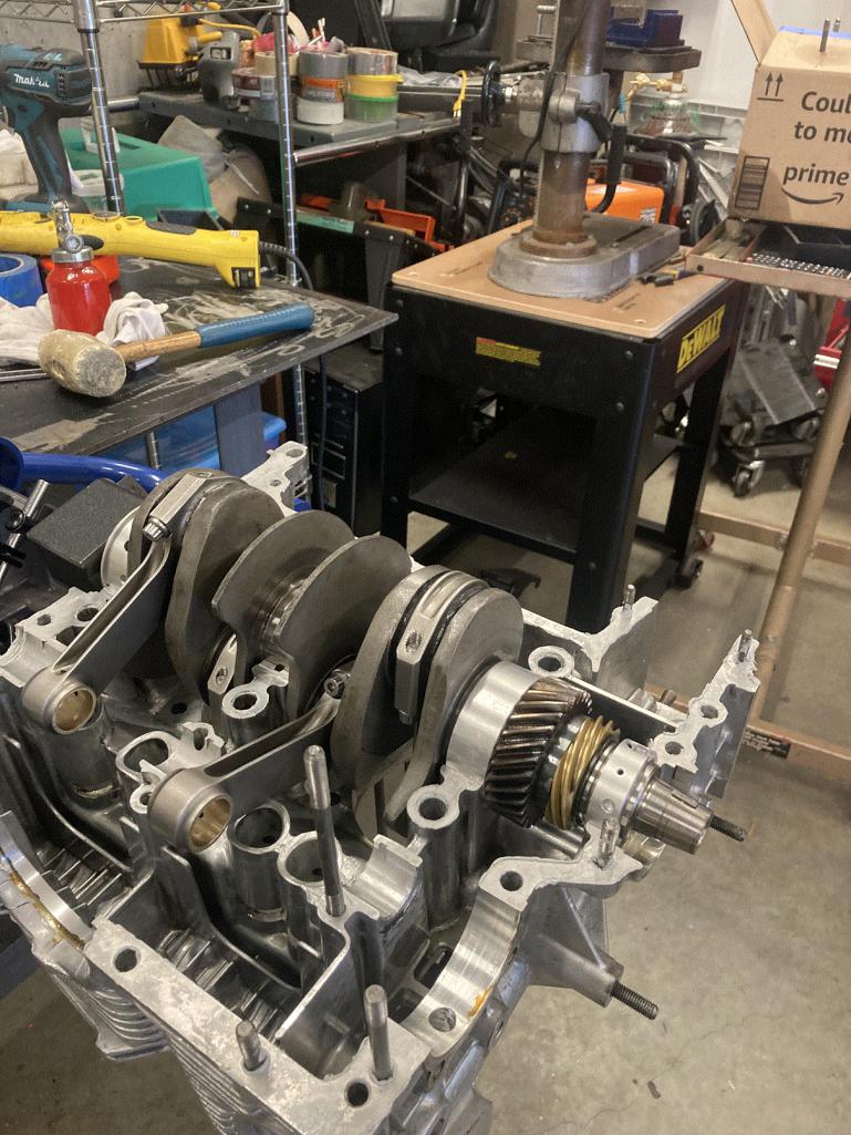 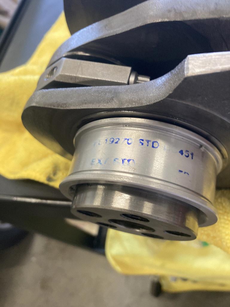 |
|
|
|
| technicalninja |
Jul 28 2024, 05:13 PM
Post
#64
|
|
Senior Member Group: Members Posts: 1,821 Joined: 31-January 23 From: Granbury Texas Member No.: 27,135 Region Association: Southwest Region |
You're testing it wrong if the flywheel isn't included in the measurement.
I'd put the dial indicator on the front of the motor... You can also place it to the disc surface of the flywheel but it's harder to get it dead straight on versus the crank snout... You need the shims installed and the flywheel lightly torqued to the crank (at least two bolts) to make this measurement. You CAN do this stuff on a half case... You just should verify your measurements during final assembly when the case is sealed up tight. The added groves look fine to me! |
|
|
|
| Superhawk996 |
Jul 28 2024, 05:54 PM
Post
#65
|
|
914 Guru Group: Members Posts: 6,464 Joined: 25-August 18 From: Woods of N. Idaho Member No.: 22,428 Region Association: Galt's Gulch |
You’ve got to dig into this - agree with Ninja that you want to do it with a flywheel mocked up to the crank.
But let’s just do some assumptions. If you really have .058; you’re not going to get there. Thickest shims is .38mm (0.015”) Since there are to be 3 shims (no more, no less) that only pulls out 0.045” of end play. Not good enough. Possibilities: crank machined wrong. Bearing thrust surface too thin. [edit add] Flywheel machined incorrectly With respect to the crank: be sure the journal throws - counterweights aren’t hitting case when the crank is fully thrusted one way or another. Off the top of my head I don’t know if there are detailed enough dimensions in the factory manual to inspect the crank and figure out what may be mismatching. I’d need to dig on that. There are known issues with aftermarket 911 bearings that I’ve lived myself and which are well documented on the bird site. Is it possible that these 914 bearings are out of spec? I wouldn’t rule that out. There are several brands of 914 bearings out there. It appears your bearings are marked as standard size which is good. I’d order another set of bearings and see. Preferably NOS like Mahle or KolbenSchmitt but those are getting rare as hens teeth and pricey. Might just try a set of sliver line bearings just to see what you get and if it helps. If all that fails and nothing is hitting the case, all hope isn’t lost. You could have a shim machined but it won’t be cheap. With respect to the flywheel. Is it new? If used - has it been remachined? There are some dimensional drawings of flywheels available - I’ll see if I can dig it up Do some more mock up with the flywheel and measure off the crank nose and let’s see what you end up with. |
 |
|
| Superhawk996 |
Jul 28 2024, 06:04 PM
Post
#66
|
|
914 Guru Group: Members Posts: 6,464 Joined: 25-August 18 From: Woods of N. Idaho Member No.: 22,428 Region Association: Galt's Gulch |
Note: be careful with that woodruff key in the crank nose - don’t lose it.
Also before you do final assembly on this you should check the fit of the crank nose to the hub with some Prussian Blue. There have been several semi-recent instances of the fan hub loosening and tearing up the crank nose when the hub doesn’t fit the crank properly. We can cross that bridge later For now - don’t lose the woodruff key and protect the crank nose from damage like burrs, dings, scratches, etc. |
|
|
|
| technicalninja |
Jul 28 2024, 06:09 PM
Post
#67
|
|
Senior Member Group: Members Posts: 1,821 Joined: 31-January 23 From: Granbury Texas Member No.: 27,135 Region Association: Southwest Region |
I think he's doing it wrong, but I do have a question for the Hawk.
(IMG:style_emoticons/default/WTF.gif) Why only three shims? "No less no more" sounds restrictive to me. I don't think the crank, or the bearing gives a shit about the number of shims... If there's a LOGICAL reason, I'd like to hear it! |
|
|
|
| technicalninja |
Jul 28 2024, 06:16 PM
Post
#68
|
|
Senior Member Group: Members Posts: 1,821 Joined: 31-January 23 From: Granbury Texas Member No.: 27,135 Region Association: Southwest Region |
|
|
|
|
| technicalninja |
Jul 28 2024, 06:30 PM
Post
#69
|
|
Senior Member Group: Members Posts: 1,821 Joined: 31-January 23 From: Granbury Texas Member No.: 27,135 Region Association: Southwest Region |
Most important!
The method you are using to determine crankshaft end play, locking the base of the dial indicator to the flywheel flange and picking a reference spot on the case, is TEXTBOOK PERFECT for 95% of the internal combustion engines ever built... It's NOT how you do it on an air-cooled VW or any other engine that uses shims between the flywheel and the crankshaft to make the thrust adjustment. That same 95% of all of the other engines don't have a cool way to adjust CS end play. You buy thicker thrust bearings or you machine/mill what you have if more clearance is needed. Edit: a chunk of modern glass, 240-600 grit wet sandpaper and WD40 is how I've increased thrust clearance every time I've needed space. I've NEVER actually had one "milled" in my life... |
|
|
|
| Superhawk996 |
Jul 28 2024, 06:43 PM
Post
#70
|
|
914 Guru Group: Members Posts: 6,464 Joined: 25-August 18 From: Woods of N. Idaho Member No.: 22,428 Region Association: Galt's Gulch |
QUOTE(technicalninja @ Jul 28 2024, 08:09 PM)  Why only three shims? "No less no more" sounds restrictive to me. I don't think the crank, or the bearing gives a shit about the number of shims... If there's a LOGICAL reason, I'd like to hear it! I don’t have definitive answer other than that’s what the factory manual specifies. The engineer in me says the reason is to have two thicker shims interfaced with the flywheel and the bearing with the third (thinnest) shim sandwiched between to protect it from damage and direct rotational contact with the bearing or flywheel. Why not four? More interfaces and places for oil to pile up into further decreasing end play? (IMG:style_emoticons/default/confused24.gif) When using factory parts four would indicate excessive wear on something? (IMG:style_emoticons/default/confused24.gif) you’ve got to admit that we are having this discussion and doing some extra checking since three won’t do it. (IMG:style_emoticons/default/huh.gif) Someone would inevitably use six thin ones rather than ordering two thick and one thin? (IMG:style_emoticons/default/confused24.gif) Having a thin shim against the rotational interface is more likely to get hung up somehow and crumple or simply wears too thin over time? (IMG:style_emoticons/default/confused24.gif) Pretty weak I know . . . That’s what I’ve got. |
|
|
|
| Superhawk996 |
Jul 28 2024, 06:51 PM
Post
#71
|
|
914 Guru Group: Members Posts: 6,464 Joined: 25-August 18 From: Woods of N. Idaho Member No.: 22,428 Region Association: Galt's Gulch |
In defense of measuring off flywheel end. I like to measure off the nose but then you end up having to get creative with indicator mounts.
As long as the flywheel isn’t being pried upon causing defection, the flywheel end measurement is fine.  |
|
|
|
| technicalninja |
Jul 28 2024, 06:56 PM
Post
#72
|
|
Senior Member Group: Members Posts: 1,821 Joined: 31-January 23 From: Granbury Texas Member No.: 27,135 Region Association: Southwest Region |
Thinking about it he could do the exact same thing he is doing with the indicator base stuck to the disc surface after mounting the flywheel and shims.
That would work fine, be easy to center the probe on the case flange. I agree! Basically, the reverse of the above picture. |
|
|
|
| Superhawk996 |
Jul 28 2024, 07:04 PM
Post
#73
|
|
914 Guru Group: Members Posts: 6,464 Joined: 25-August 18 From: Woods of N. Idaho Member No.: 22,428 Region Association: Galt's Gulch |
Yup always multiple ways to do it.
As long as indicator mount is rigid, indicator is perpendicular, and nothing is being forced / deflected it’s all fair game. |
|
|
|
| technicalninja |
Jul 28 2024, 07:22 PM
Post
#74
|
|
Senior Member Group: Members Posts: 1,821 Joined: 31-January 23 From: Granbury Texas Member No.: 27,135 Region Association: Southwest Region |
Robroe, we need pictures: do multiangle shots if possible
Oil pump Rocker arm assemblies Pushrods lifters Are there any fresh drill marks on the crank? Fresh grinding marks on the rods? Most of the time balance holes/marks are obvious. They are not centered, sort of haphazard, and some of them will be STUPID shallow. What I'm hunting is evidence of balancing... |
|
|
|
| Robroe |
Jul 28 2024, 08:12 PM
Post
#75
|
|
Member Group: Members Posts: 76 Joined: 10-August 21 From: Wenatchee, WA Member No.: 25,793 Region Association: Pacific Northwest |
QUOTE(technicalninja @ Jul 28 2024, 07:16 PM) Yes, the flywheel was bolted to crank/engine and shims in place. But I’ll mock it up again in the morning and make sure flywheel is torqued. Then measure again on flywheel and nose end of flywheel and report. Hope it’s just my lack of measuring skill and knowledge. Also, I’m considering taking rods off the crank to clean oil passages and reassemble using same rod bearings. |
|
|
|
| technicalninja |
Jul 28 2024, 08:48 PM
Post
#76
|
|
Senior Member Group: Members Posts: 1,821 Joined: 31-January 23 From: Granbury Texas Member No.: 27,135 Region Association: Southwest Region |
Tip for bearing indexing:
Mark ALL of the rods with a number. Mark the caps too. Make these marks at exactly the same place on all rods/caps and I mark the rod/cap interface one side only with a tiny groove that crosses the parting line. I will intentionally offset the groove mark for each of the four so I CAN use just the groove itself to determine the correct cap for the individual rod. I once had a set of rods shot peened and lost all of my marks. The shot peener didn't keep the order indexed when he dissembled them for "final cleaning" That was a PIA! Minimum is a sharpie, but I use a vibrating etch tool with a diamond tip and make TINY marks. If you splurge on the diamond point for that tool it can ONLY be used perfectly vertical. Deviate slightly and you will get to buy another tip... When you side the rod bearings out of their journals clean them immediately (B12 is what I use) and sharpie the back sides of each bearing. "1" on the rod side. "1C" on the cap side would be the shells for #1 Watch orientation during disassembly. The bearing locator tabs should face each other. The bearing should not fall out of the journal. You should have to "rotate" them out of each journal. Each bearing should have a tiny bit of overlap regarding how they fit into the journal. When you "flush out" one side the other side should have a cunt hair of bearing proud of the part line. This is bearing crush and it's critical. You just need to verify you have a little on each one. You will be checking that more precisely during assembly. Keep bearings clean in a compartment container. Doesn't have to be fancy. I use egg cartons all the time. After you get everything apart you can check/achieve balancing on some of the parts. No harder than the grooving you did to the case. You will need an accurate scale. $15 on Amazon will probably buy you something usable. If I was that far down, I'd DAMN sure go all the way... |
|
|
|
| technicalninja |
Jul 28 2024, 09:41 PM
Post
#77
|
|
Senior Member Group: Members Posts: 1,821 Joined: 31-January 23 From: Granbury Texas Member No.: 27,135 Region Association: Southwest Region |
Have the next question regarding the CS end play issue.
Stock or aftermarket flywheel? If it's still bad after rechecking AND it has an aftermarket flywheel, I'd want to try a stocker before I did a bunch of measuring/head scratching trying to figure out WHERE my extra play was. |
|
|
|
| Robroe |
Jul 29 2024, 09:01 PM
Post
#78
|
|
Member Group: Members Posts: 76 Joined: 10-August 21 From: Wenatchee, WA Member No.: 25,793 Region Association: Pacific Northwest |
Did another mock up today to remeasure crank end play. This time I installed the bearing dowels, made sure the crank was fully set and installed the flywheel with no seal and removed the crank o ring. Tightened the crank bolts to around 40lbs. End play was suddenly down to .002"!!!. I must have left the crank bolts too loose previously so got bad measurements as y'all suspected. I feel confident that I can assemble and adjust to .004" with available shims. See Pict of measurements.
Also checked for signs of balancing. The rods show signs of minor grinding to remove metal and pistons have drill head marks also showing signs of removing metal. Looks like I'm in the clear to move on to cleaning, getting gasket kit and assembly lube/sealants. 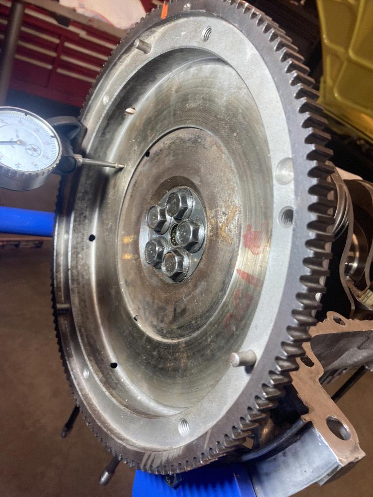 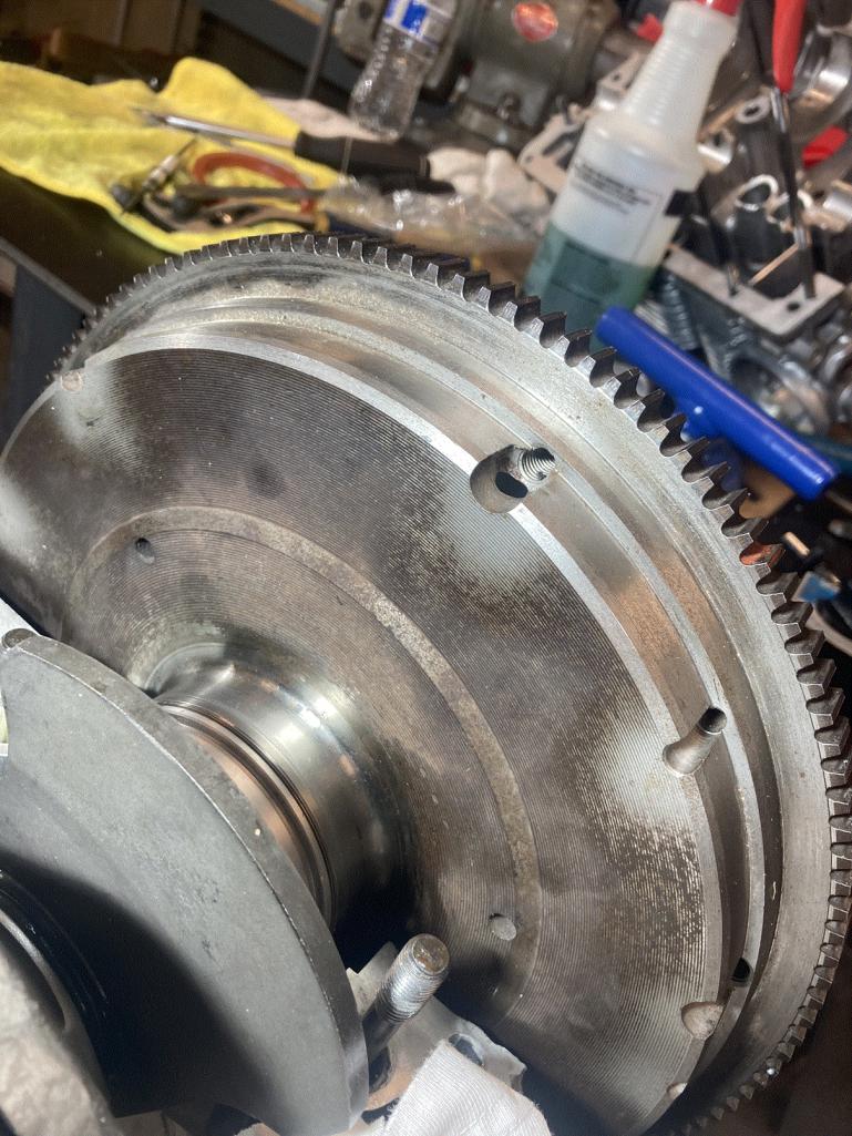 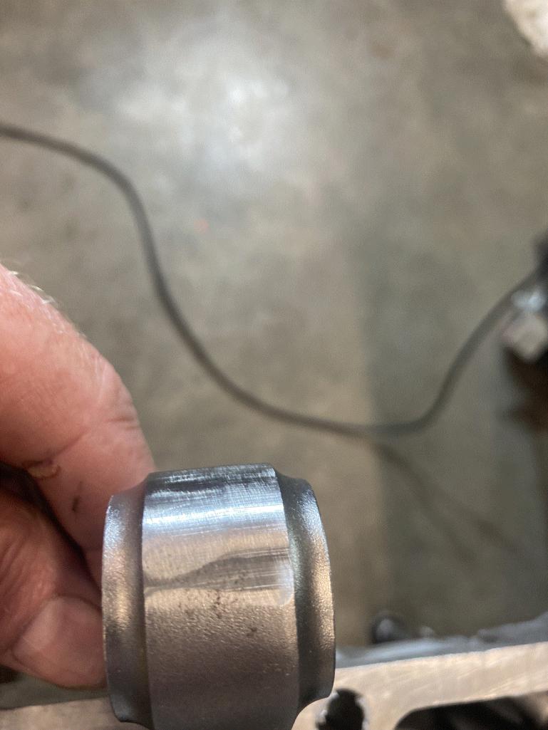  |
|
|
|
| technicalninja |
Jul 29 2024, 09:10 PM
Post
#79
|
|
Senior Member Group: Members Posts: 1,821 Joined: 31-January 23 From: Granbury Texas Member No.: 27,135 Region Association: Southwest Region |
Target DOWN!
Glad it's working out! I'd expect same type of random metal removal marks somewhere on the crank. Now, the cheap way of balancing the rotating assembly is to assemble everything and JUST do the balancing adjustment on the flywheel/pressure plate and front crank pully. The balance evidence MIGHT be limited to just those items and the assembly needs to stay INTACT for it to be considered balanced... Since you have this stuff apart I would re-check the weights/balance on everything. A blueprint sheet SHOULD have the weights of the important shit listed. I would create a BP sheet on that engine. |
|
|
|
| technicalninja |
Jul 29 2024, 09:17 PM
Post
#80
|
|
Senior Member Group: Members Posts: 1,821 Joined: 31-January 23 From: Granbury Texas Member No.: 27,135 Region Association: Southwest Region |
It looks like the clutch disc surface has seen rotation???
Thought you said never run... Still has nice "Blanchard" marks on it. Not run long if it was. I'd clean that surface up and re-use as is. |
|
|
|
|
2 User(s) are reading this topic (2 Guests and 0 Anonymous Users)
0 Members:

|
Lo-Fi Version | Time is now: 16th September 2024 - 12:55 PM |
Invision Power Board
v9.1.4 © 2024 IPS, Inc.