|
|
|
Porsche, and the Porsche crest are registered trademarks of Dr. Ing. h.c. F. Porsche AG.
This site is not affiliated with Porsche in any way. Its only purpose is to provide an online forum for car enthusiasts. All other trademarks are property of their respective owners. |
|
|

  |

| Montreal914 |
 Jan 4 2025, 09:16 AM Jan 4 2025, 09:16 AM
Post
#81
|
|
Advanced Member  Group: Members Posts: 2,177 Joined: 8-August 10 From: Claremont, CA Member No.: 12,023 Region Association: Southern California |
2270 = 78.4 x 96mm
2258 = 78 x 96mm 78.4 cranks were made in the past but I believe current offering (Scat and others) seems to be 78mm. EDIT: Also, benefit of 78mm is you don't need any clearance (or just a hint) in the case when using the H beam rods. I think the rods lengths you have now might be better aligned with 78mm, but there are better qualified people with experinece here who are chiming in. I am simply sharing what I have read across multiple forums (World, Shoptalkforums, Raby, etc...). Fun stuff! (IMG:style_emoticons/default/smile.gif) |
   |

 
|
| cgnj |
Jan 4 2025, 11:19 AM
Post
#82
|
|
Senior Member Group: Members Posts: 735 Joined: 6-March 03 From: Medford, NJ Member No.: 403 Region Association: None |
Since we are all spending your money, oil spray groove for rods.
 techbull.pdf ( 141.2k )
Number of downloads: 504
techbull.pdf ( 141.2k )
Number of downloads: 504 |
|
|
|
| technicalninja |
Jan 4 2025, 11:32 AM
Post
#83
|
|
Advanced Member Group: Members Posts: 2,531 Joined: 31-January 23 From: Granbury Texas Member No.: 27,135 Region Association: Southwest Region |
QUOTE(friethmiller @ Jan 3 2025, 10:25 PM)  QUOTE(technicalninja @ Jan 3 2025, 09:10 PM) It would be useful to have the shim measurements. You should have two sets of four. A set should have same thickness in all. Please check. Might be possible to deck registers and achieve proper quench with a single shim. Be handy to verify deck height of all 4. If things are good, you'll be +/- .001 @cgnj I asked for skirt pics because of "short rod". I didn't see any evidence of bad thrust in the skirts he showed. I didn't see them all, but it looks like the rod length works OK. Sure! Each cylinder had two shims: one measuring .088 inches and another at .090 inches. I did do a rough deck height of .022 with just the .090 shim. I think that would mean, as it stands now, I would need a single shim of .108 to hit a .040 deck. I’ll double check everything in the morning for all 4 cylinders. Based on the fact that my pistons are already proud of the cylinders (w/o shims). If material is removed from the case registers, wouldn’t that increase the size of the shim needed? Wouldn’t reducing the crank size by 2-4mm makes more sense? I mentioned earlier that I have a W block that I can use - assuming it checks out. No skirt damage on any of these pistons. Morning Update: With a 0.090 shim installed under each cylinder and using pvc pipes +washer/nuts holding everything down I get the following piston-deck clearances: #1 = 0.023, #2 = 0.023, #3 = 0.024, #4 = 0.024 KICK ASS! you're with .001! Too bad one of those shims wasn't bigger than .120; that's what I was hoping for! Yes, cutting registers means thicker shims. I thought I saw a link once to custom sized shims. You order them then wait type of stuff... If I had your set up, I'd run it as-is (as long as I had valve clearance). I'd target 9.5 via minor combustion chamber massaging. I'd add ceramic coatings. I believe I'd use the 9520 LN cam and their suggested valve springs (along with the cam junk I listed before). Hastings rings, plateau honed, heads fly cut MINIMUM to achieve "perfect" jug to head seal. Registers cut flat (better to go minimum and go "bespoke" on the shim.) I'd think about stronger head studs, probably include. No FREAKING way I'd install an oil pump without the double O-rings around the body. Those O-rings can eliminate air being sucked in on the entrance side. Critical in my book! I'd expect to have to add additional oil cooling, but I'd look closely at the TR cooler kits that mount a Setrab in the back. I'd definitely use his T-stat set up with 215-degree T-stat. I would verify temps FIRST before adding oil cooling. I'd provision carbs to the rich side and be conservative with timing. I'd be watching the CHT, AFR and if avaialble EGTs. I'd really want some kind of knock sensor too! They made half-assed kits for detection and it's possible to make "Det-Cans" yourself. These are basically a microphone attached to the engine, running to amplified headphones, You REALLY can hear detonation! I'd plug my det cans into the aux port on my modern radio head unit. Now the whole sound system is part of the det cans... You would be SHOCKED at what you can hear with det cans. Loose sheet metal, bolts stand out. A rod knock sounds like King Kong is beating on it! That 123 distributor (and the stock ignition system) is one of the weak points IMO. I'd probably add an MS for the ignition system alone. Move up to a waste spark or COP from the start. I like COP! (IMG:style_emoticons/default/devil.gif) Having full ignition control IS 50% of the battle IMO. And it will be easier to talk you into proper FI if it's already in the car! (IMG:style_emoticons/default/ninja.gif) |
 |
|
| burton73 |
Jan 4 2025, 02:07 PM
Post
#84
|
|
Senior member, and old dude Group: Members Posts: 4,056 Joined: 2-January 07 From: Los Angeles Member No.: 7,414 Region Association: Southern California |
QUOTE(friethmiller @ Jan 4 2025, 05:40 AM) QUOTE(densible1 @ Jan 3 2025, 04:09 PM) @burton73 here's link to those 2270 build snaps. https://artbox.industryartworks.com/s/of8CKoNyptHf6X7 mark Thanks to @densible1 and @burton73 for the photos. Very interesting to see one of these old RAT engines. I'm still studying all these photos. BTW, I modified my windage tray but with four 1/2" drain holes but Jake's mod is a lot larger. I also plan to do the RMS mod this time around, too (IMG:style_emoticons/default/idea.gif) @burton73 - you said it was a 2270. Pistons look larger than 96mm and the CB rods are 5.4". Do you recall the crank size? Mark says 96MM on pistons and we know nothing on the crank. This eng was in one of Oscars cars at one time. The crank wasn't very pretty as some custom cranks I have seen on the web for different cars. Not sure that matters just something I noticed. Best Bob B |
|
|
|
| technicalninja |
Jan 4 2025, 02:55 PM
Post
#85
|
|
Advanced Member Group: Members Posts: 2,531 Joined: 31-January 23 From: Granbury Texas Member No.: 27,135 Region Association: Southwest Region |
I would LOVE to know why the pics don't post over.
They show up in "preview" just fine but when you try to include them in the reply you look like a moron... Sometimes they post over fine as well (IMG:style_emoticons/default/headbang.gif) (IMG:style_emoticons/default/headbang.gif) (IMG:style_emoticons/default/headbang.gif) QUOTE(friethmiller @ Dec 31 2024, 05:39 PM) Engine pics Tear down: #3 Main (split) Bearing. Notice scoring on backside. Plastigauge says clearance is between .002 - .003 but closer to .003 (too much clearance). Not sure how damaged those are, might be less than it looks. I'd check crank for straightness first. QUOTE(friethmiller @ Dec 31 2024, 07:06 PM) Camshaft Bearings: These look worse than the mains... They look "pinched" There IS a chance that it is because of the bearing manufacture and all do this now. This MIGHT be "normal". I'd install the cam and old bearings in the case halves and see "how it fit" If I could. Crankshaft: Crankcase: I'm not seeing fresh machine work here... Did they just "verify" line bore or do it? QUOTE(friethmiller @ Dec 31 2024, 07:23 PM) More Pics: Note: any perpendicular marks are from my dial bore gauge More pics of main bearings: Bearing #1 (small one): Looks like a tiny bit off center, not horrible. Bearing #2: Bearing #3: See previous images of split bearing. Bearing #4 (Rear main): These bearings look OK to me Heads (cylinder side): This shows the area I would want machined perfect before the engine went back together. Where the jug "contacts" is what I'm after. The far-left chamber appears "brinelled" in this area. Small pits of material are missing. This is the most stressed seal surface in the engine. The Nickies fix here is to go big bore in the OD (requiring machine work to heads) and then using THICK walls. You're stuck with THIN! This is one of "limiters" on this engine and needs to be PERFECT!. Improving that seal is the reason I would research higher strength head studs. (mentioned before). @Superhawk996 , can you please post the pic of your Nickies showing this? That would help me emphasize this point. I'd check the crank for straightness with a set of V-blocks. You can half/ass do this with the main bearings, one case halve, and the crank. Install end bearings on crank, drop in case. Dial indicator on center journal, rotate crank. V-blocks mounted on a bench makes it easier and allows you to check "run out" on any of the journals. If the crank is bent... This is easy and inexpensive to test as long as you already have the dial indicator. V blocks can be made out of anything. Metal and hard plastic are better IMO. |
|
|
|
| Superhawk996 |
Jan 4 2025, 03:37 PM
Post
#86
|
|
914 Guru Group: Members Posts: 7,967 Joined: 25-August 18 From: Woods of N. Idaho Member No.: 22,428 Region Association: Galt's Gulch |
100mm
 |
|
|
|
| technicalninja |
Jan 4 2025, 03:45 PM
Post
#87
|
|
Advanced Member Group: Members Posts: 2,531 Joined: 31-January 23 From: Granbury Texas Member No.: 27,135 Region Association: Southwest Region |
At this level of build I would be hunting thermal control.
I'd try to keep the heat out of things via ceramics and try to improve the transfer rate to remove the heat that makes it into the metal. I'd detail the cooling passages through the head, remove all of the casting flash. I'd research coatings to improve heat transfer, maybe use. I'd finish the tins out tight, no air leaks, tight booties on everything. I'd improve the cooling abilities as much as possible. One thing that does help! Tangerine Racing has a race car with a 4-5" duct through the cabin directly into the fan. Like a raccoon Habitrail through the car! Sadly, that wouldn't work for me either... |
|
|
|
| technicalninja |
Jan 4 2025, 04:01 PM
Post
#88
|
|
Advanced Member Group: Members Posts: 2,531 Joined: 31-January 23 From: Granbury Texas Member No.: 27,135 Region Association: Southwest Region |
Thanks SH!
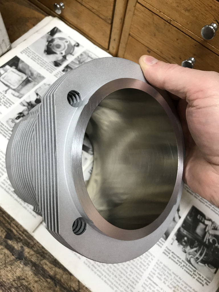
Look at how thick the walls are. This is on a 100mm bore. 100X82= 2576! (IMG:style_emoticons/default/beerchug.gif) |
|
|
|
| technicalninja |
Jan 4 2025, 04:24 PM
Post
#89
|
|
Advanced Member Group: Members Posts: 2,531 Joined: 31-January 23 From: Granbury Texas Member No.: 27,135 Region Association: Southwest Region |
Need P-W clearance. If they "sized for forged" and installed cast you're screwed.
1/2 way up piston skirt perpendicular to the pin axis on piston. Diameter of bore. Dial caliper can get close enough to tell if you have a problem. Best with micrometers. |
|
|
|
| friethmiller |
Jan 4 2025, 04:42 PM
Post
#90
|
|
Senior Member Group: Members Posts: 1,431 Joined: 10-February 19 From: Austin, TX Member No.: 22,863 Region Association: Southwest Region |
Just got back in from welding on the front cross panel on the LE. I’ll do the P-W check after dinner. Thanks (IMG:style_emoticons/default/ninja.gif)
|
|
|
|
| technicalninja |
Jan 4 2025, 05:05 PM
Post
#91
|
|
Advanced Member Group: Members Posts: 2,531 Joined: 31-January 23 From: Granbury Texas Member No.: 27,135 Region Association: Southwest Region |
and yet another thought...
I slipped a set of stock jugs into a stock 2.0 head. Without the compression shim the jug sits deep enough in the head to almost contact it. This closes off the top of the first fin to cooling flow. Your heads looked "worked" in this aera. Make sure there is a good airflow path between head and jug. Don't bury first fin closely to head. |
|
|
|
| friethmiller |
Jan 4 2025, 08:18 PM
Post
#92
|
|
Senior Member Group: Members Posts: 1,431 Joined: 10-February 19 From: Austin, TX Member No.: 22,863 Region Association: Southwest Region |
(IMG:style_emoticons/default/ninja.gif) Used a digital micrometer on all piston skirts, 90 degrees from and on-level with the pins, and got 95.925 mm (3.7765748 in). Next, I zeroed the dial-bore gauge to 95.925mm on the micrometer (in vise). Tested all cylinders at the 12-6 o’clock position. Got a P to W gap of .0025in - .003in depending on the cylinder.
|
|
|
|
| technicalninja |
Jan 4 2025, 08:32 PM
Post
#93
|
|
Advanced Member Group: Members Posts: 2,531 Joined: 31-January 23 From: Granbury Texas Member No.: 27,135 Region Association: Southwest Region |
You need to be halfway down the skirt, below the pin bore.
Note: this is a guess on my part. The pistons should have come with a card that states where the measurement is supposed to be taken from. Pistons are NOT round cylinders. They are more like barrels and have a taper to them. There can be .020"+ of variation top to bottom. 1/2 the skirt below the oil control ring is very common spot. I think you'll be at 0.002" and are fine. I'd want .002+ maybe .0025 Edit: I want to see your micrometer! .001 mm is .000039" That is 3 HUNDRED THOUSANDS of an inch! You've SO blown me away! It's damn hard to work in tenths! You're 10X tighter!!!! NFW! At this small a measurement temperature alone will alter things... Are you REPEATABLE at the third decimal point? If you are I want to see your tool!!!!! |
|
|
|
| friethmiller |
Jan 4 2025, 09:13 PM
Post
#94
|
|
Senior Member Group: Members Posts: 1,431 Joined: 10-February 19 From: Austin, TX Member No.: 22,863 Region Association: Southwest Region |
QUOTE(technicalninja @ Jan 4 2025, 08:32 PM) You need to be halfway down the skirt, below the pin bore. Note: this is a guess on my part. The pistons should have come with a card that states where the measurement is supposed to be taken from. Pistons are NOT round cylinders. They are more like barrels and have a taper to them. There can be .020"+ of variation top to bottom. 1/2 the skirt below the oil control ring is very common spot. I think you'll be at 0.002" and are fine. I'd want .002+ maybe .0025 Edit: I want to see your micrometer! .001 mm is .000039" That is 3 HUNDRED THOUSANDS of an inch! You've SO blown me away! It's damn hard to work in tenths! You're 10X tighter!!!! NFW! At this small a measurement temperature alone will alter things... Are you REPEATABLE at the third decimal point? If you are I want to see your tool!!!!! It’s the digital tool spitting out to .0001. Any thing more precise is me converting b/w units. I claim no super measuring powers. Repeatable? Somewhat. I take several measurements at each point to make sure it’s repeatable. I think that skirt measurement is good. I moved the micrometer up and down the skirt to find the maximum. I don’t have any piston card but will attempt to find it. I’ll re-measure once I do. Photo of digital micrometer: 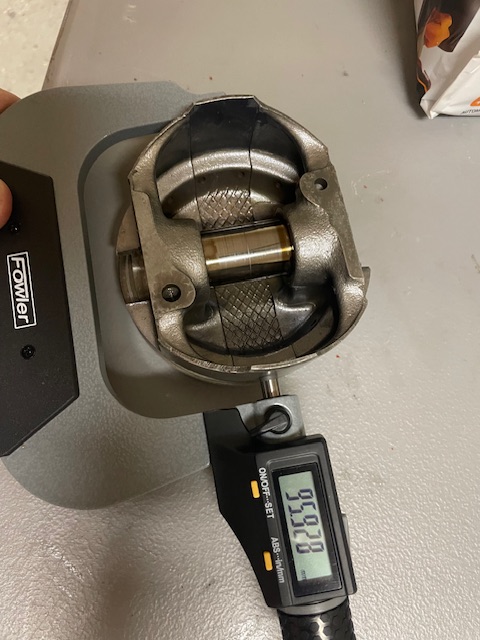 BTW, I split the case and removed the crank. Inserted the cam bearings, added lube, and mounted the camshaft. It moves freely, not tight at all BUT its endplay is large. Probably due to bad geometry, side loading, not sure. I used a .019 feeler gauge at the thrust - cam interface. Obviously it was loosing material here from the abuse. Something else to verify later during assembly with the new cam. Link to larger/custom cylinder spacers: https://www.geneberg.com/cat.php?name=Cylin...&cPath=3016 |
|
|
|
| technicalninja |
Jan 5 2025, 12:04 AM
Post
#95
|
|
Advanced Member Group: Members Posts: 2,531 Joined: 31-January 23 From: Granbury Texas Member No.: 27,135 Region Association: Southwest Region |
That range is GREAT!
It almost looks like a .090 and .040 (the cheap ones) would get you close. Lots of .010 increment shims. Still, if that price is for 4, I'm in! I didn't "jive" with the 90.5 vs 92 measurements. But if those will fit on your jugs that "hunt for source" is done. That mic is cool! Really shows 3rd decimal point in MM! That is SOOOO small! Found it! Look at the resolution! https://www.higherprecision.com/products/mi...AiABEgLCo_D_BwE Actually, for that level of precision $500 is cheap! And you have just created TOOL ENVY! (IMG:style_emoticons/default/devil.gif) (IMG:style_emoticons/default/devil.gif) (IMG:style_emoticons/default/devil.gif) (IMG:style_emoticons/default/devil.gif) I want your mic! (IMG:style_emoticons/default/ninja.gif) |
|
|
|
| technicalninja |
Jan 5 2025, 12:25 AM
Post
#96
|
|
Advanced Member Group: Members Posts: 2,531 Joined: 31-January 23 From: Granbury Texas Member No.: 27,135 Region Association: Southwest Region |
You have accurate tools.
You measured close to .003 P-W You DON"T have a choice, the bores must be at minimum honed by a machine shop with real honing machine. This will add some clearance... One thing I'd do is add moly coating to the skirts of the piston. This will tighten the clearance a small amount. Having the suggested P-W clearance and ring gaps from KB would help. I've seen old posts by Raby talking about these, His roll pin incident and his (At least then) suggestion of Hastings rings. I think he mentioned ring gaps. |
|
|
|
| friethmiller |
Jan 5 2025, 10:20 AM
Post
#97
|
|
Senior Member Group: Members Posts: 1,431 Joined: 10-February 19 From: Austin, TX Member No.: 22,863 Region Association: Southwest Region |
QUOTE(technicalninja @ Jan 5 2025, 12:25 AM) You have accurate tools. You measured close to .003 P-W You DON"T have a choice, the bores must be at minimum honed by a machine shop with real honing machine. This will add some clearance... One thing I'd do is add moly coating to the skirts of the piston. This will tighten the clearance a small amount. Having the suggested P-W clearance and ring gaps from KB would help. I've seen old posts by Raby talking about these, His roll pin incident and his (At least then) suggestion of Hastings rings. I think he mentioned ring gaps. I was having trouble seeing the micrometer so thought I’d try the digital out. Meant to purchase the 2-3 inch but it worked out for the P-W check. That price for all 3 is pretty good. Time to use that Christmas money, Rick! |
|
|
|
| technicalninja |
Jan 5 2025, 01:43 PM
Post
#98
|
|
Advanced Member Group: Members Posts: 2,531 Joined: 31-January 23 From: Granbury Texas Member No.: 27,135 Region Association: Southwest Region |
It's both the sight and the feel in tenths...
I've never worked in hundredths! What do you speak of? "Christmas Money" As I am the patriarch my money turns into "Christmas Money" and is given to others (my spawn and their spawn). by the time Christmas is over I have NONE! Ba Humbug! |
|
|
|
| technicalninja |
Jan 5 2025, 03:39 PM
Post
#99
|
|
Advanced Member Group: Members Posts: 2,531 Joined: 31-January 23 From: Granbury Texas Member No.: 27,135 Region Association: Southwest Region |
QUOTE(friethmiller @ Jan 4 2025, 08:18 PM) (IMG:style_emoticons/default/ninja.gif) Used a digital micrometer on all piston skirts, 90 degrees from and on-level with the pins, and got 95.925 mm (3.7765748 in). Next, I zeroed the dial-bore gauge to 95.925mm on the micrometer (in vise). Tested all cylinders at the 12-6 o’clock position. Got a P to W gap of .0025in - .003in depending on the cylinder. This is for the folks reading along... Fred did something here that ALL machinist do! Beginners almost always check piston with a mic and the bore with an internal dial caliper. They then try to take the difference between two separate tools. Fred zeroed his dial bore gauge to the mic (in a vise! It always takes a vice for me too). He then used the bore gauge to check clearance. He IS using a single tool to determine his measurement! Even a cheap bottom of the line bore gauge is FREAKING ACCURATE when used in this manner. I've had to give this "use one tool for measurements" speech many. many times... Fred did that shit automatically! It's HALF the battle! (IMG:style_emoticons/default/first.gif) (IMG:style_emoticons/default/first.gif) (IMG:style_emoticons/default/first.gif) (IMG:style_emoticons/default/first.gif) The process he used and his uber accurate mic means his .0025-.003 measurements will be stupid close... I believe him and most of the time I wonder "are they measuring correctly?" Now, he did make a beginner mistake... I test the cylinders at all different angles. I don't intentionally choose one clocking. I'll watch my needle to get a feel for the circle. Taper and concentricity (roundness) are very important! If I vary more than .0005, I want to straighten that out. Power honing, on a real machine that holds the stones in a micrometer style base CAN slightly correct taper and out of round. Sprung stones or a berry hone don't correct shit! |
|
|
|
| friethmiller |
Jan 6 2025, 01:59 PM
Post
#100
|
|
Senior Member Group: Members Posts: 1,431 Joined: 10-February 19 From: Austin, TX Member No.: 22,863 Region Association: Southwest Region |
QUOTE(cgnj @ Jan 4 2025, 11:19 AM) Since we are all spending your money, oil spray groove for rods.
techbull.pdf ( 141.2k )
Number of downloads: 504Is this necessary on non-stock, H-Rods? Curious where this "v groove" is actually made. The diagram is a bit confusing, IMO. Anyone have a picture of this modification done on a rod? |
|
|
|
|
2 User(s) are reading this topic (2 Guests and 0 Anonymous Users)
0 Members:

|
Lo-Fi Version | Time is now: 28th July 2026 - 02:28 PM |
Invision Power Board
v9.1.4 © 2026 IPS, Inc.