|
|
|
Porsche, and the Porsche crest are registered trademarks of Dr. Ing. h.c. F. Porsche AG.
This site is not affiliated with Porsche in any way. Its only purpose is to provide an online forum for car enthusiasts. All other trademarks are property of their respective owners. |
|
|

  |

| emerygt350 |
 Mar 8 2025, 11:52 AM Mar 8 2025, 11:52 AM
Post
#41
|
|
Advanced Member  Group: Members Posts: 2,712 Joined: 20-July 21 From: Upstate, NY Member No.: 25,740 Region Association: North East States |
I don't think the line size either way is going to create a problem.
|
   |

 
|
| Superhawk996 |
Mar 8 2025, 12:11 PM
Post
#42
|
|
914 Guru Group: Members Posts: 6,841 Joined: 25-August 18 From: Woods of N. Idaho Member No.: 22,428 Region Association: Galt's Gulch |
(IMG:style_emoticons/default/agree.gif)
Stay focused and don’t get distracted by line sizes - not the problem. Using large line for return makes no sense. The volume of return fuel is always less than what is supplied. The large line in tank is the one with the mesh filter sock. You don’t want to be filtering returned fuel. Yeah - I get filter on suction should negate anything in the fuel but that sock is a needless restriction in the return which is in principle what you’re trying to negate by using the larger line? Doesn’t make sense. Sure you can take the sock out and completely redesign the fuel system. None of this will get the engine running Hopefully not being too harsh - not my intent. |
 |
|
| Literati914 |
Mar 8 2025, 03:48 PM
Post
#43
|
|
Senior Member Group: Members Posts: 1,871 Joined: 16-November 06 From: Dallas, TX Member No.: 7,222 Region Association: Southwest Region |
QUOTE(emerygt350 @ Mar 8 2025, 11:52 AM)  I don't think the line size either way is going to create a problem. QUOTE(Superhawk996 @ Mar 8 2025, 12:11 PM) OK, so why did Porsche decrease the feed line diameter when they moved the pump to the front? just for the heck of it ? (IMG:style_emoticons/default/biggrin.gif) Come on Superhawk, you're a scientist man - isn't there something to be said for increasing pressure with a drop in volume (large pipe vs small pipe analogy)? |
|
|
|
| Superhawk996 |
Mar 8 2025, 04:09 PM
Post
#44
|
|
914 Guru Group: Members Posts: 6,841 Joined: 25-August 18 From: Woods of N. Idaho Member No.: 22,428 Region Association: Galt's Gulch |
QUOTE(Literati914 @ Mar 8 2025, 05:48 PM) QUOTE(emerygt350 @ Mar 8 2025, 11:52 AM) I don't think the line size either way is going to create a problem. QUOTE(Superhawk996 @ Mar 8 2025, 12:11 PM) OK, so why did Porsche decrease the feed line diameter when they moved the pump to the front? just for the heck of it ? (IMG:style_emoticons/default/biggrin.gif) Come on Superhawk, you're a scientist man - isn't there something to be said for increasing pressure with a drop in volume (large pipe vs small pipe analogy)? You raise a valid point They dropped line sizes because it’s a lot more efficient to push fuel with the pump in the front vs using the larger OD line as a suction line when the pump was in the rear. It also highly likely they dropped line size as a cost savings which would offset the need to have moved to pressure rated plastic fuel line when the moved the pump to the front. But seriously line size isn’t your issue. Being an engineer I’ll be happy to debate fluid dynamics and we can talk about Bernoulli equations and Reynolds number, all day long but that isn’t going to help you get your engine going. Put a fuel pressure gauge at the rear of the car on the fuel rail and figure out why you’re not getting pressure to the fuel pressure regulator. |
|
|
|
| Literati914 |
Mar 8 2025, 06:01 PM
Post
#45
|
|
Senior Member Group: Members Posts: 1,871 Joined: 16-November 06 From: Dallas, TX Member No.: 7,222 Region Association: Southwest Region |
QUOTE(Superhawk996 @ Mar 8 2025, 04:09 PM) They dropped line sizes because it’s a lot more efficient to push fuel with the pump in the front .. (IMG:style_emoticons/default/beerchug.gif) , and there you go.. thanks I'm making the change. Seriously, I appreciate the input and don't care to debate you on this - but It's a fairly easy and basically free change to make and I'm not all that convinced that the large pipe as a return has any real drawbacks. Guess I'll see - Besides, unless I'm misunderstanding his comments earlier in this thread @VaccaRabite has his running this way or similar. Probably more than one way to skin a cat, couldn't hurt to try. You're advice to check pressure with a gauge is a good one - can you recommend a gauge and where/how it's plugged into the system? The small bolt at the top of the rail seems too small for a gauge hook up, it's like an M4 or so bolt I think. Thanks as always! |
|
|
|
| Superhawk996 |
Mar 8 2025, 08:17 PM
Post
#46
|
|
914 Guru Group: Members Posts: 6,841 Joined: 25-August 18 From: Woods of N. Idaho Member No.: 22,428 Region Association: Galt's Gulch |
Any fuel pressure test gauge will work but you need a gauge capable of reading up to about 65psi to cover the pump you are using which is supposed to have a pressure range of 45-65 psi according to what I found online for that pump.
Harbor freight version shown but could be any gauge rated for use with fuels with an appropriate pressure range. I’d just rig up a T or use the one in the kit. Using the T you can plumb it in on the output of your fuel pump to make sure the pump is outputting pressure. You can then plumb the T into the fuel rail loop to verify you have 29 psi at the injectors. If you really care you can plumb it into the fuel return line and see what the pressure is there (who cares). You still haven’t confirmed that you have the fuel pressure regulator plumbed correctly at the END of the fuel loop. This isn’t optional. Review the diagram Spoke posted in post #33. The fuel pressure regulator system is designed to have the regulator bleeding off excess flow to the return line while maintaining about 30psi of pressure in the fuel rail loop. Stated differently — the regulator ISN’T designed to take in some fuel pump pressure (let’s just say 50 psi) and output 30 psi of regulated pressure on the front end of the fuel loop. Stated differently one more time - the fuel pressure regulator doesn’t work like an 2 port air pressure regulator. 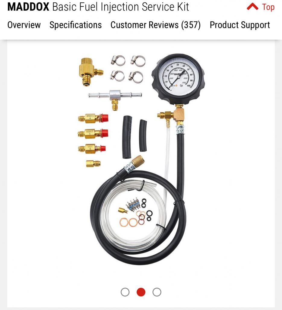 Hot wire your fuel pump if need be to do the pressure testing so you’re not dependent on the ECU to pulse the pump at key on or to be receiving a signal from the trigger points to run the pump during cranking. |
|
|
|
| Literati914 |
Mar 9 2025, 12:48 AM
Post
#47
|
|
Senior Member Group: Members Posts: 1,871 Joined: 16-November 06 From: Dallas, TX Member No.: 7,222 Region Association: Southwest Region |
So much good info, I appreciate it.
Maybe I haven't stated it enough here but, I feel I've verified the FPR routing/plumbing enough.. There is an apprx 3ft. (5/16") fuel hose that runs behind the airbox from the passenger's side to the FPR on the driver's side. There is NO fuel there. If I accidently crossed up the hoses coming from the tunnel, there would be fuel there. I do however have fuel right after the #2/#1 rail (driver's side just before input to FPR) as it should be. Also the FPR is NOT mounted on the stand backwards, if it were mounted backwards, the output side would face the driver's side wall (obviously wrong), so there's only one logical way to mount the hoses to the FPR in it's correctly mounted state. Again unless I'm missing something, which is not out of the question. I'm gonna look at getting a test gauge, thanks again. |
|
|
|
| Superhawk996 |
Mar 9 2025, 01:32 AM
Post
#48
|
|
914 Guru Group: Members Posts: 6,841 Joined: 25-August 18 From: Woods of N. Idaho Member No.: 22,428 Region Association: Galt's Gulch |
Just going to post this so we have common points of reference. Realize you have a twin port pump and it’s located at front. Supply line highlighted.
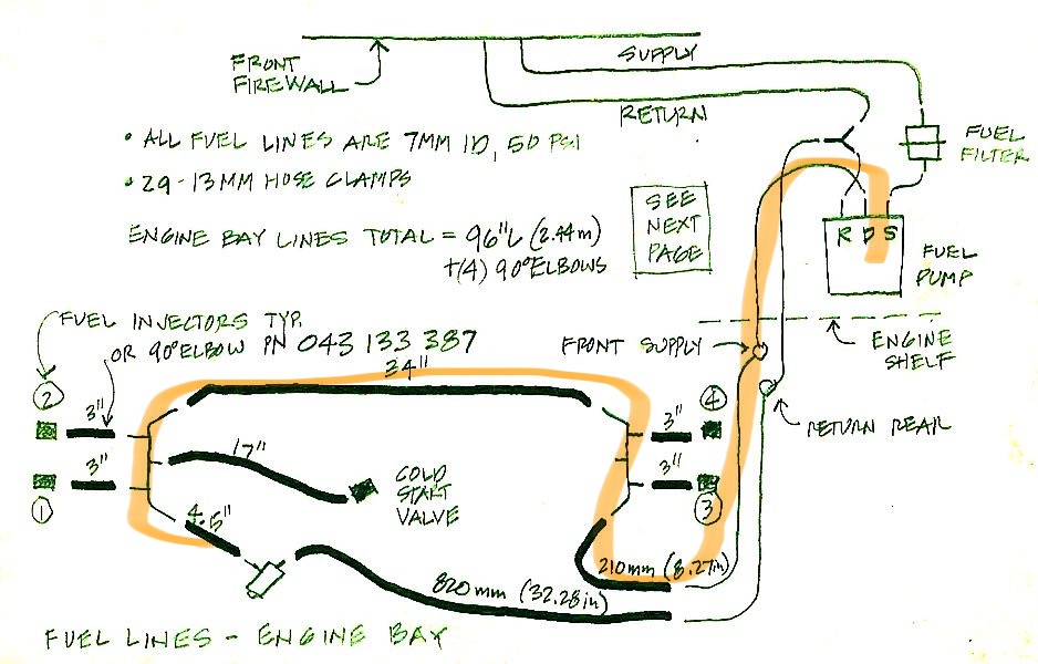 Let’s see what pressures look like when you get a gauge on it. |
|
|
|
| emerygt350 |
Mar 9 2025, 06:18 AM
Post
#49
|
|
Advanced Member Group: Members Posts: 2,712 Joined: 20-July 21 From: Upstate, NY Member No.: 25,740 Region Association: North East States |
The ports for the pressure tester are on the steel rails.
|
|
|
|
| Literati914 |
Mar 9 2025, 09:39 AM
Post
#50
|
|
Senior Member Group: Members Posts: 1,871 Joined: 16-November 06 From: Dallas, TX Member No.: 7,222 Region Association: Southwest Region |
QUOTE(Superhawk996 @ Mar 9 2025, 01:32 AM) Just going to post this so we have common points of reference. Realize you have a twin port pump and it’s located at front. Supply line highlighted. Yes correct, that's how I've always had it routed. |
|
|
|
| Literati914 |
Mar 9 2025, 09:40 AM
Post
#51
|
|
Senior Member Group: Members Posts: 1,871 Joined: 16-November 06 From: Dallas, TX Member No.: 7,222 Region Association: Southwest Region |
QUOTE(emerygt350 @ Mar 9 2025, 06:18 AM) The ports for the pressure tester are on the steel rails. Happen to know the fitting size? |
|
|
|
| Superhawk996 |
Mar 9 2025, 10:19 AM
Post
#52
|
|
914 Guru Group: Members Posts: 6,841 Joined: 25-August 18 From: Woods of N. Idaho Member No.: 22,428 Region Association: Galt's Gulch |
Remove the screw - slip fuel hose tube over the stub, connect to gauge.
The T as I proposed will let you insert the gauge anywhere. But using the fuel rail port is the real deal. If you have proper pressure on the rail, everything else is OK. You’ll only need the T if you want to know pressure in other places like the front of the car or in the return loop. Either of these would only be of interest for troubleshooting a lack of proper pressure at the rail. |
|
|
|
| Literati914 |
Mar 9 2025, 10:30 AM
Post
#53
|
|
Senior Member Group: Members Posts: 1,871 Joined: 16-November 06 From: Dallas, TX Member No.: 7,222 Region Association: Southwest Region |
QUOTE(Superhawk996 @ Mar 9 2025, 10:19 AM) Remove the screw - slip fuel hose tube over the stub, connect to gauge. The T as I proposed will let you insert the gauge anywhere. But using the fuel rail port is the real deal. If you have proper pressure on the rail, everything else is OK. You’ll only need the T if you want to know pressure in other places like the front of the car or in the return loop. Either of these would only be of interest for troubleshooting a lack of proper pressure at the rail. OK got it. Also, looking at your posted routing pic again.. it occurs to me that I may have missed running a fuel line over to the CSV from the rail (IMG:style_emoticons/default/wacko.gif) . I doubt that has anything to do with the pressure situation, but needs to be there I'm sure. It's rainy here- will check in a couple days. |
|
|
|
| Superhawk996 |
Mar 9 2025, 11:43 AM
Post
#54
|
|
914 Guru Group: Members Posts: 6,841 Joined: 25-August 18 From: Woods of N. Idaho Member No.: 22,428 Region Association: Galt's Gulch |
Cold start valve only comes into play around freezing temperatures.
Honestly I’d leave it out for now until you get engine running. |
|
|
|
| Literati914 |
Mar 18 2025, 03:07 PM
Post
#55
|
|
Senior Member Group: Members Posts: 1,871 Joined: 16-November 06 From: Dallas, TX Member No.: 7,222 Region Association: Southwest Region |
QUOTE(Superhawk996 @ Mar 9 2025, 02:32 AM) Just going to post this so we have common points of reference. Realize you have a twin port pump and it’s located at front. Supply line highlighted. Let’s see what pressures look like when you get a gauge on it. Ok, the illustration above may be for a 2.0L .. but I'm seeing that my 1.7L is different. The CSV (yes attached at the plenum) is splitting the fuel line between the fuel rails (fuel hose between #4 and #2 inj). PET refers to CVS as a Solenoid - unless I'm looking at the wrong item. I understand that the CSV as hooked up in the illustration would not cause any fuel pressure issues.. I have to wonder though, in my configuration (with an input and an output), do they ever get clogged? I'll be checking FP later and report back. |
|
|
|
| 930cabman |
Mar 18 2025, 03:41 PM
Post
#56
|
|
Advanced Member Group: Members Posts: 3,986 Joined: 12-November 20 From: Buffalo Member No.: 24,877 Region Association: North East States |
Did this engine get started?
|
|
|
|
| Literati914 |
Mar 18 2025, 06:16 PM
Post
#57
|
|
Senior Member Group: Members Posts: 1,871 Joined: 16-November 06 From: Dallas, TX Member No.: 7,222 Region Association: Southwest Region |
No, I've just come back to it after ordering a pressure gauge. Working on it.
OK, I hooked the gauge up just before the #3/4 injector bank on passenger's side... I was able to build up 40psi by turning the key to the on position several times in a row (maybe 10). It held that pressure but dropped to about 28psi after 40 min. or so. Then I hooked the gauge up to the nipple in the middle of the #1/2 fuel rail, driver's side. After about 30 on/off's at the key, I still had no fuel pressure there. So - I'm thinking the CSV could be the only thing stopping fuel from getting over to the driver's side. Maybe I can take it out of the loop by plumbing a 5/16 to 5/16 fitting in it's place. Does that sound like the correct next move? |
|
|
|
| emerygt350 |
Mar 19 2025, 08:22 AM
Post
#58
|
|
Advanced Member Group: Members Posts: 2,712 Joined: 20-July 21 From: Upstate, NY Member No.: 25,740 Region Association: North East States |
This really sounds like the routing is not correct. You should be going from pump to rails to regulator to tank return. The csv comes off the driver side rail as a side circuit. Is that what yours is doing? Pictures?
|
|
|
|
| Superhawk996 |
Mar 19 2025, 08:36 AM
Post
#59
|
|
914 Guru Group: Members Posts: 6,841 Joined: 25-August 18 From: Woods of N. Idaho Member No.: 22,428 Region Association: Galt's Gulch |
QUOTE(Literati914 @ Mar 18 2025, 08:16 PM) So - I'm thinking the CSV could be the only thing stopping fuel from getting over to the driver's side. Maybe I can take it out of the loop by plumbing a 5/16 to 5/16 fitting in it's place. Does that sound like the correct next move? Yes - agree That 1.7l cold start injector is sort of weird in that it should flow between inlet and outlet with no obstruction but it sure sounds like yours is plugged Replace with a straight though barb fitting. Bypass the cold start valve for troubleshooting. The cold start injector only comes into play around freezing temps anyway. |
|
|
|
| Superhawk996 |
Mar 19 2025, 08:39 AM
Post
#60
|
|
914 Guru Group: Members Posts: 6,841 Joined: 25-August 18 From: Woods of N. Idaho Member No.: 22,428 Region Association: Galt's Gulch |
QUOTE(emerygt350 @ Mar 19 2025, 10:22 AM) This really sounds like the routing is not correct. You should be going from pump to rails to regulator to tank return. The csv comes off the driver side rail as a side circuit. Is that what yours is doing? Pictures? Nope. 1.7L cold start injector is like a T and has a slightly different fuel flow and routing vs 2.0l. It could be plumbed like a 2.0l (assuming a single inlet 2.0L CSV fits a 1.7L plenum??? Based on pic I think the flange is different???) but would result in more hose running around the engine bay to the frontside of the 1.7L plenum. I posted the 2.0L fuel line diagram because I couldn’t find one for a 1.7l. Wanted as a graphic aid to ensure that the fuel pressure regulator was at the end of the fuel circuit and so we would have common reference points. I apologize for any confusion I caused by posting the 2.0L fuel line diagram. 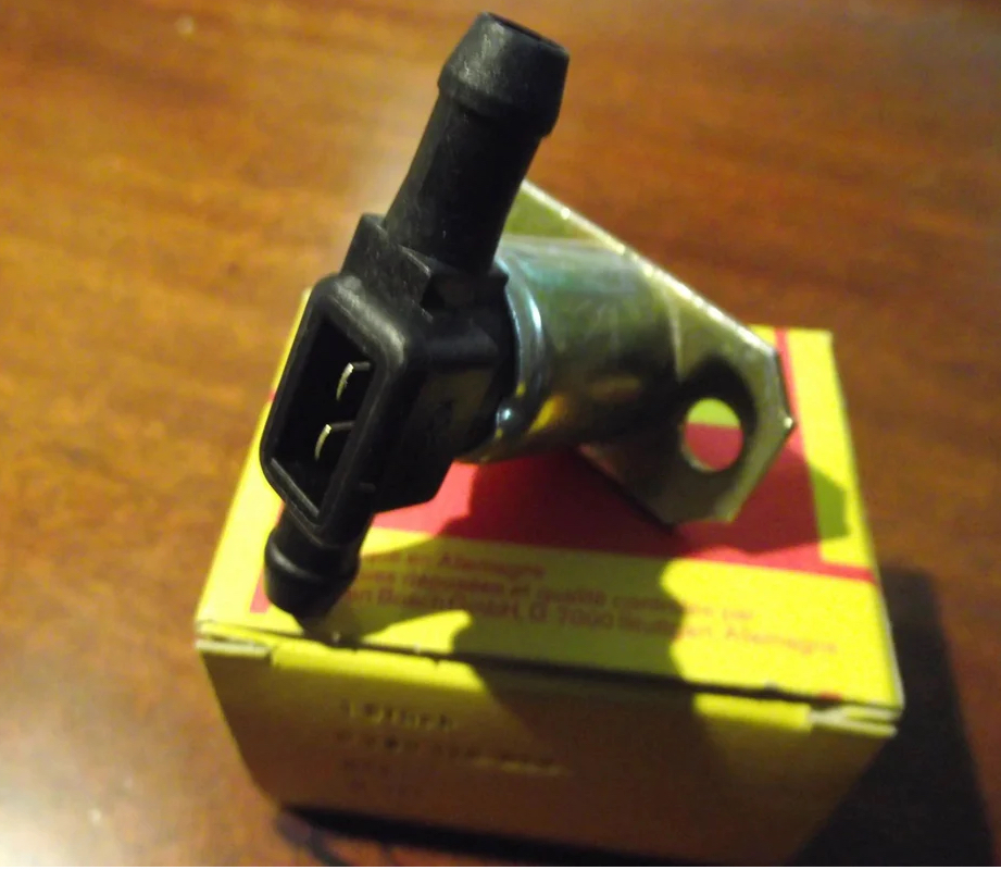 |
|
|
|
|
6 User(s) are reading this topic (4 Guests and 0 Anonymous Users)
2 Members: rjames, Literati914

|
Lo-Fi Version | Time is now: 19th March 2025 - 11:27 AM |
Invision Power Board
v9.1.4 © 2025 IPS, Inc.