|
|

|
Porsche, and the Porsche crest are registered trademarks of Dr. Ing. h.c. F. Porsche AG.
This site is not affiliated with Porsche in any way. Its only purpose is to provide an online forum for car enthusiasts. All other trademarks are property of their respective owners. |
|
|
  |
| andys |
 Jan 6 2006, 10:58 AM Jan 6 2006, 10:58 AM
Post
#161
|
|
Advanced Member     Group: Members Posts: 2,165 Joined: 21-May 03 From: Valencia, CA Member No.: 721 Region Association: None 
|
Oops, wrong pic...try this one.
Andys Attached image(s) 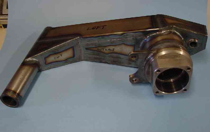
|
| TimT |
 Jan 6 2006, 11:36 AM Jan 6 2006, 11:36 AM
Post
#162
|
||
|
retired     Group: Members Posts: 4,033 Joined: 18-February 03 From: Wantagh, NY Member No.: 313 |
(IMG:http://www.914world.com/bbs2/html/emoticons/hijacked.gif)
This is a 930 trailing arm. we got punted, and the trailing arm broke. now back to the 914 trailing arm Attached image(s) 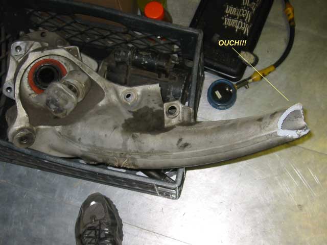
|
||
| jluetjen |
 Jan 6 2006, 12:48 PM Jan 6 2006, 12:48 PM
Post
#163
|
|
Member   Group: Members Posts: 53 Joined: 5-January 06 From: Westford, MA Member No.: 5,373 |
OK, Here are a couple of cases that I've made up as well as the earlier data for reference.
First, Just 1000 lbs -Z, no bulkhead. 232 1.027E-05 -4.044E-05 -1.355E-03 -3.071E-04 6.046E-05 2.470E-06 Now, same model, but with all 3 forces inflicted upon it. 232 -1.035E-03 -1.537E-02 1.325E-03 3.710E-04 -6.441E-05 1.560E-03 Now the model with the bulkhead and all 3 forces. 232 -1.034E-03 -1.534E-02 1.310E-03 3.533E-04 -6.467E-05 1.560E-03 First New Case: A single gusset of the same 2mm material down the short side per the attached drawing. (Note that the key node is now node 242 after the nodes were renumbered) It appears that twist was reduced in Y and increased in X as a result of this change. 242 -1.148E-03 -1.394E-02 1.323E-03 3.504E-04 -6.904E-05 1.408E-03 I doubt that we can put a gusset on the other side without interfereing with the wheel or tire. Click here for full size image. This post has been edited by McMark: Jan 8 2006, 11:41 AM Attached image(s) 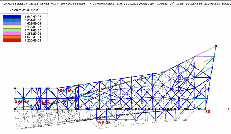
|
| jluetjen |
 Jan 6 2006, 02:24 PM Jan 6 2006, 02:24 PM
Post
#164
|
|
Member   Group: Members Posts: 53 Joined: 5-January 06 From: Westford, MA Member No.: 5,373 |
OK. Now I've modified the model to include a full width bulkhead down the inside between the 2 red lines. It's better then having a bulkhead across the piece, but not as good as an external gussset. Here's the numbers...
First, Just 1000 lbs -Z, no bulkhead. 232 1.027E-05 -4.044E-05 -1.355E-03 -3.071E-04 6.046E-05 2.470E-06 Now, same model, but with all 3 forces inflicted upon it. 232 -1.035E-03 -1.537E-02 1.325E-03 3.710E-04 -6.441E-05 1.560E-03 Now the model with the bulkhead and all 3 forces. 232 -1.034E-03 -1.534E-02 1.310E-03 3.533E-04 -6.467E-05 1.560E-03 First New Case: A single gusset of the same 2mm material down the short side per the attached drawing. (Note that the key node is now node 242 after the nodes were renumbered) It appears that twist was reduced in Y and increased in X as a result of this change. 242 -1.148E-03 -1.394E-02 1.323E-03 3.504E-04 -6.904E-05 1.408E-03 Now with the longitudinal internal bulkhead (actually a "floor" since it's horizontal) of 2 mm materia. (The key node is 232 again). 232 -1.070E-03 -1.421E-02 1.317E-03 3.449E-04 -6.727E-05 1.541E-03 BTW - Keep an eye on the colors. According to this simulation there are some areas up close to the smaller tubes where axial stress on the material is in the neighborhood of 10,000 lb/sq inch. Click here for full size image. Attached image(s) 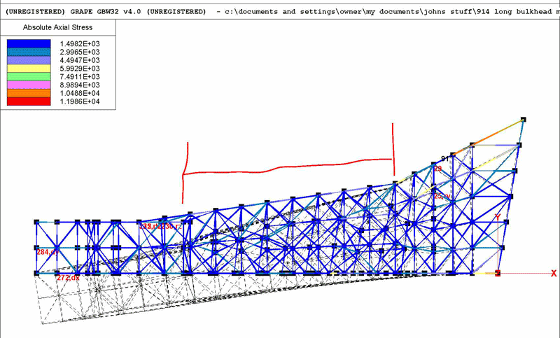
|
| Porcharu |
 Jan 6 2006, 02:50 PM Jan 6 2006, 02:50 PM
Post
#165
|
|
Senior Member    Group: Members Posts: 1,314 Joined: 27-January 05 From: Campbell, CA Member No.: 3,518 Region Association: Northern California |
Another idea for reducing "pucker factor" If we know where the "pucker" or dimple is occuring would a small tube or 2 (or a bolt) welded across the area work as well as the bulkhead (or almost as well.) This would be a very easy way to go if it works - I'm a little nervous about cutting my trailing arms in half and welding them back together. Drilling a few holes and welding in some tubes would be a snap.
Steve |
| McMark |
 Jan 6 2006, 03:19 PM Jan 6 2006, 03:19 PM
Post
#166
|
|
914 Freak!                Group: Retired Admin Posts: 20,179 Joined: 13-March 03 From: Grand Rapids, MI Member No.: 419 Region Association: None |
Steve, those were my thoughts awhile back. Drill a few holes through the entire arm at strategic points and weld in rod. Also thought the same thing for longitudinals. (IMG:http://www.914world.com/bbs2/html/emoticons/wink.gif)
|
| jluetjen |
 Jan 6 2006, 03:21 PM Jan 6 2006, 03:21 PM
Post
#167
|
|
Member   Group: Members Posts: 53 Joined: 5-January 06 From: Westford, MA Member No.: 5,373 |
Steve;
I suspect that what would would happen is that if you could know where a "pucker" were to occur -- and buttressed up that area -- that the stress would then move to another unreinforced area and pucker that area even more. It's kind of the "fat lady in the girdle" sort of excercise. All of that force needs to be transmitted through the trailing arm. If you restrain it in one area, it will pop out in another. |
| ChrisFoley |
 Jan 7 2006, 08:04 AM Jan 7 2006, 08:04 AM
Post
#168
|
|
I am Tangerine Racing      Group: Members Posts: 7,980 Joined: 29-January 03 From: Bolton, CT Member No.: 209 Region Association: None 
|
A point approximating the center of the wheel bearing would be the best the position to apply the forces.
Since the location of point 232 is so close to the longitudinal axis of the trailing arm, when you apply a Y axis load the torguing force (ft-lbs) is much lower than the actual force (lbs) applied. More of the load ends up being applied to the rear support point compared to a real trailing arm. The current model works well for Z axis loads much but it does decrease both X and Y moments significantly. Speaking of X axis forces, I think they would be much smaller than half a ton, even braking in a straight line. You could argue that since the moment is smaller the effect is similar but you also pointed out some pretty high force concentrations in one example, on the order of magnitude (1E+05) of the yield strength (4E+05) of the metal. It seems that a little more accurate model is still needed to see if there is any more likelihood of component failure. In order to more accurately model the location of force application you could simply attach a cone to the surface and use the point of the cone instead of the current point 232. |
| jluetjen |
 Jan 7 2006, 08:55 AM Jan 7 2006, 08:55 AM
Post
#169
|
|
Member   Group: Members Posts: 53 Joined: 5-January 06 From: Westford, MA Member No.: 5,373 |
Good morning Chris. Good thoughts. Give me a minute to upload the stuff that I just finished and then we can run a couple more simulations with the modified force vectors.
|
| jluetjen |
 Jan 7 2006, 08:59 AM Jan 7 2006, 08:59 AM
Post
#170
|
|
Member   Group: Members Posts: 53 Joined: 5-January 06 From: Westford, MA Member No.: 5,373 |
OK. Here's a spreadsheet with the different cases that we ran and then some new ones. The big changes is that I've extended the hub out by 2 inches as Chris just described. The forces are still being applied to the center of that "hub". I then ran a model adding a strut as Mugs914 showed in his pictures, and then another test with the external gusset on the short side of the arm. It looks like the gusset provides the biggest improvement in the Y-displacement. I'll upload the overhead view of each simulation in a minute.
This post has been edited by McMark: Jan 8 2006, 11:35 AM Attached image(s) 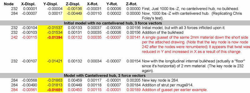
|
| jluetjen |
 Jan 7 2006, 09:01 AM Jan 7 2006, 09:01 AM
Post
#171
|
|
Member   Group: Members Posts: 53 Joined: 5-January 06 From: Westford, MA Member No.: 5,373 |
Base model with the cantelivered hub.
Click for full size image. This post has been edited by McMark: Jan 8 2006, 11:32 AM Attached image(s) 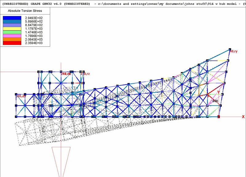
|
| jluetjen |
 Jan 7 2006, 09:05 AM Jan 7 2006, 09:05 AM
Post
#172
|
|
Member   Group: Members Posts: 53 Joined: 5-January 06 From: Westford, MA Member No.: 5,373 |
With Mugs914's strut
Click here for a full size image. This post has been edited by McMark: Jan 8 2006, 11:29 AM Attached image(s) 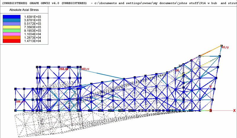
|
| jluetjen |
 Jan 7 2006, 09:06 AM Jan 7 2006, 09:06 AM
Post
#173
|
|
Member   Group: Members Posts: 53 Joined: 5-January 06 From: Westford, MA Member No.: 5,373 |
Attached image(s) 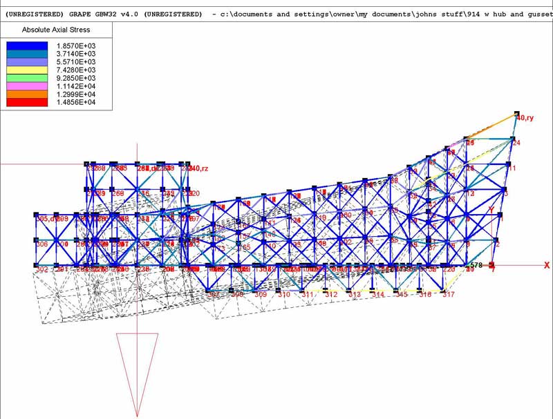
|
| jluetjen |
 Jan 7 2006, 09:11 AM Jan 7 2006, 09:11 AM
Post
#174
|
|
Member   Group: Members Posts: 53 Joined: 5-January 06 From: Westford, MA Member No.: 5,373 |
Chris; If I were to assume that your 914 corners at about 1.5 g's (round figure), what sort of braking forces should I use? We can then do some quick vector addition to come up with some more precise force levels. I think that the models that we've done so far are certainly relevent to try out the different strategies for reducing the Y displacement (aka: Toe). Then we can optimise a strategy to ensure that the stresses are kept to manageable levels.
I'll check back in a few minutes. BTW, how fabricatable would it be to use one piece of metal as both the longitudinal "floor" and the external gusset. Say -- cut a line on both sides of the arm, insert the flat piece of metal and weld from both sides? (IMG:http://www.914world.com/bbs2/html/emoticons/dry.gif) |
| Eric_Shea |
 Jan 7 2006, 12:30 PM Jan 7 2006, 12:30 PM
Post
#175
|
|
PMB Performance                Group: Admin Posts: 19,299 Joined: 3-September 03 From: Salt Lake City, UT Member No.: 1,110 Region Association: Rocky Mountains  |
John,
Is the rear caliper inner adjuster tube factored into your model? |
| jluetjen |
 Jan 7 2006, 01:27 PM Jan 7 2006, 01:27 PM
Post
#176
|
||
|
Member   Group: Members Posts: 53 Joined: 5-January 06 From: Westford, MA Member No.: 5,373 |
I checked it by adding a 1.125"x12 tube there and it didn't make any difference. The numbers were exactly the same for at least 5 digits. |
||
| ChrisFoley |
 Jan 8 2006, 07:10 AM Jan 8 2006, 07:10 AM
Post
#177
|
|
I am Tangerine Racing      Group: Members Posts: 7,980 Joined: 29-January 03 From: Bolton, CT Member No.: 209 Region Association: None 
|
John,
I was away all day working on Tangerine 356 Conversion header issues. I just noticed where you identify your x,y,z axes. I intuitively had chosen the z to be the (real world) horizontal - lateral axis and the y axis to be the vertical, as opposed to choosing the coordinates while looking "down" on the trailing arm. I have to be more careful I guess. (IMG:style_emoticons/default/unsure.gif) |
| ChrisFoley |
 Jan 8 2006, 07:38 AM Jan 8 2006, 07:38 AM
Post
#178
|
|
I am Tangerine Racing      Group: Members Posts: 7,980 Joined: 29-January 03 From: Bolton, CT Member No.: 209 Region Association: None 
|
I just identified a big difference betweeen a real trailing arm and the GRAPE model. The box tube is actually perpendicular to the pivot axis. This affects the position of the node where you are applying forces relative to the restrained points at the front, therefore alters the moment arm length for x axis rotations. If I'm not mistaken x axis rotation (in the model coordinate system) is what I've been measuring with my tests.
Have you tested my bulkhead using the new point 284? I would still like to place some focus on x axis rotations as something to reduce. Also, what are the units for this column? |
| jluetjen |
 Jan 8 2006, 10:54 AM Jan 8 2006, 10:54 AM
Post
#179
|
||||||||||
|
Member   Group: Members Posts: 53 Joined: 5-January 06 From: Westford, MA Member No.: 5,373 |
Actually, on the piece that I have, the small tube is about 7+/- degree from perpindicular with the weld seam up the trailing arm, and the large tube is an additional 7+/- degrees from perpindicular in the opposite direction. This places the hub (I'm guessing) at about 15 degree from the axis of the smaller tube. Why do I say 15 degrees instead of 14? Because on the 911, the pivot axis for the rear semi-trailing arm assembly (from the spring plate's pivot through the trailing arm pivot) is also around 15 degrees. I wouldn't be surprised if Porsche designed the 914 rear end to use similar suspension geometry as the 911, although the way that they got there mechanically would be different. Anyhow, I digress...
Yes -- and not really. Yes it does. That is one of the compromises I made in my model. I wasn't about to spend the time to calculate all of the coordinates 7 degrees off of square with the origin coordinates. And then do the hub an additional 7 degrees off of that. That's the kind of stuff that gave me brain cramp at the start (IMG:http://www.914world.com/bbs2/html/emoticons/wacko.gif) and why it took me almost a month from when I borrowed the arm until I actually started. I just decided to simplify things and assume that everything was square to start. Once I got the basic model done, I then went back and moved the small tube about 7 degrees from the main arm. Right now the large tube with the hub is perpindicular with the main arm. ( (IMG:http://www.914world.com/bbs2/html/emoticons/idea.gif) Hmmmm, as I'm writing this it just dawned on me how I could shift the hub assembly by about 7 degrees without a huge amount of recalculation. All it will take is the time to reconstruct the web.) But I don't think it makes a huge difference from what I've seen running the models for a couple of reasons. 1) We've got 3 vectors of force on the model which sum up to a force which is 45 degrees back (away from the small tube) and 45 degrees up. Now shift that about 15 degrees. Basically we could get the same result as moving the total force 15 degrees by increasing the force in the -Y direction, and reducing the force by a corresponding amount in the -X direction. Either way, it's not going to be a magnitude change (Moving the decimal point essentially) as we're seing between the Y and the Z distortion. That is a function of the shape of the structure. 2) One of the features of the software is that I can make an animation of the structure under load. What I can print is only the total displacement (the dotted lines). If you watch it move, you'll see that it's basically bending in a fairly even arc. Shifting the forces by a few degrees just isn't going to change that by much.
Yes, or more specifically the Z displacement. This is what I have highlighted in the first two rows of the spreadsheet. But after running the model, one of the things that jumped out at me pretty early is that given that the pivot axis at the front, and the coil-over attachment at the tail of the arm (constraining it in the Z direction), the arm is not really twisting that much at all. But after I put the lateral and (cantelivered) -X force vectors on it, that the arm displaced a whole lot in the Y direction -- about 10X the Z displacement. You can see this on the spreadsheet. This is why I standardized on posting the pictures from the top view. If you make yourself a test fixture where you put the arm's pivot axis vertical, and you restrain it perpindicular to that so that it doesn't pivot, then apply the same force on it that you have previously in a twisting fashion. I suspect that you will find that the arm deflects about 10X what you saw on your first experiments. The model suggests (by an order of 10X) that this is where your oversteer is coming from.
I'm going to be out all afternoon, I'll try to do this (as well as combine the external gusset with an internal "floor" ) some time this week. Unfortunately, with this software, adding features inside of a model is a real test of visual accuity. (IMG:http://www.914world.com/bbs2/html/emoticons/blink.gif)
The units of the spreadsheet data should be inches which is the standard units I used for the model. I had to do some off-line calculations to estimate the geometric properties of a 1-inch square by 2 mm's thick. The properties of steel are stored on a second table which I just used as is. If you (or anyone else) is interested, this is what I calculated the geometric properties to be. If someone knows this better then me -- Please speak up now!!! (IMG:http://www.914world.com/bbs2/html/emoticons/chair.gif) [B]Geometry for a 1 inch square by 2 mm strip [B] X-Area: .078792 J-Inertia: .000112 YY-Inertia: 4.1E-5 ZZ-Inertia: .006565 Y-Recovery: .5 Z-Recovery: .5 T-Recovery: .5 |
||||||||||
| Eric_Shea |
 Jan 8 2006, 10:58 AM Jan 8 2006, 10:58 AM
Post
#180
|
|
PMB Performance                Group: Admin Posts: 19,299 Joined: 3-September 03 From: Salt Lake City, UT Member No.: 1,110 Region Association: Rocky Mountains  |
Can someone resize John's pics to 800pxls W?
|
  |
2 User(s) are reading this topic (2 Guests and 0 Anonymous Users)
0 Members:

|
Lo-Fi Version | Time is now: 3rd April 2025 - 06:07 PM |
Invision Power Board
v9.1.4 © 2025 IPS, Inc.


