|
|

|
Porsche, and the Porsche crest are registered trademarks of Dr. Ing. h.c. F. Porsche AG.
This site is not affiliated with Porsche in any way. Its only purpose is to provide an online forum for car enthusiasts. All other trademarks are property of their respective owners. |
|
|
  |
| jluetjen |
 Jan 8 2006, 11:00 AM Jan 8 2006, 11:00 AM
Post
#181
|
|
Member   Group: Members Posts: 53 Joined: 5-January 06 From: Westford, MA Member No.: 5,373 |
I would if I could -- but I can't. (IMG:http://www.914world.com/bbs2/html/emoticons/confused24.gif)
|
| Eric_Shea |
 Jan 8 2006, 11:07 AM Jan 8 2006, 11:07 AM
Post
#182
|
|
PMB Performance                Group: Admin Posts: 19,304 Joined: 3-September 03 From: Salt Lake City, UT Member No.: 1,110 Region Association: Rocky Mountains  |
No problemo... I 'think' someone here can.
It would just be easier to read and look at all the points if they were 800. That seems to be the perfect size for a 1024 view. |
| ChrisFoley |
 Jan 8 2006, 12:35 PM Jan 8 2006, 12:35 PM
Post
#183
|
|
I am Tangerine Racing      Group: Members Posts: 8,016 Joined: 29-January 03 From: Bolton, CT Member No.: 209 Region Association: None 
|
QUOTE Chris; If I were to assume that your 914 corners at about 1.5 g's (round figure), what sort of braking forces should I use? We can then do some quick vector addition to come up with some more precise force levels. I would also use 1.5g for the max limit of braking force. Most of the braking is done by the front tires, so I would estimate one rear wheel at (2000*1.5/2*0.25) 375lb max x axis force. I doubt this would ever occur simultaneously with max y or z forces. QUOTE I think that the models that we've done so far are certainly relevent to try out the different strategies for reducing the Y displacement (aka: Toe). Then we can optimise a strategy to ensure that the stresses are kept to manageable levels. QUOTE BTW, how fabricatable would it be to use one piece of metal as both the longitudinal "floor" and the external gusset. Say -- cut a line on both sides of the arm, insert the flat piece of metal and weld from both sides? QUOTE This places the hub (I'm guessing) at about 15 degree from the axis of the smaller tube. QUOTE If you make yourself a test fixture where you put the arm's pivot axis vertical, and you restrain it perpindicular to that so that it doesn't pivot, then apply the same force on it that you have previously in a twisting fashion. I suspect that you will find that the arm deflects about 10X what you saw on your first experiments. QUOTE The units of the spreadsheet data should be inches which is the standard units I used for the model |
| jluetjen |
 Jan 8 2006, 07:52 PM Jan 8 2006, 07:52 PM
Post
#184
|
||||
|
Member   Group: Members Posts: 53 Joined: 5-January 06 From: Westford, MA Member No.: 5,373 |
Rotations are in radians.
Can you give me an estimated CG height for a 914? If in doubt, it's usually pretty close to the crankshaft height. The other thing is the approximate roll-center heights -- front and rear. With that information I've got another software program where I can run it through and come up with a pretty good estimate. On the other hand if you have some data that supports that estimate, that's fine too. You're estimate sounds a little low given that your car is a rear-mid-engined car -- and a fairly low one at that. For the sake of simplicity, let's just assume that each wheel is braking a quarter of the car's mass, so we're talking about 2000 * 1.5/4 = 750. By the same token, we're talking about a quarter of the car's lateral force at the same G level, so 750 lbs lateraly. (IMG:http://www.914world.com/bbs2/html/emoticons/idea.gif) If I remember (or rather can read) my trig correctly, 750 lbs in one direction plus 750 lbs in a perpendicular direction will equal (excel calculation.... COS(RADIANS(45 (degrees)))*750 = 530.33 lbs. Right? So this is what I should use for our force vectors. Now we just need to estimate the forces in roll. BTW, Apparently Grape's calculations tend to overestimate the displacement by about 20% (most likely as a margining factor). This is based on a model done of an actual FF frame compared to experimental measurements taken off of the real frame. |
||||
| Brett W |
 Jan 8 2006, 08:44 PM Jan 8 2006, 08:44 PM
Post
#185
|
|
Advanced Member     Group: Members Posts: 2,859 Joined: 17-September 03 From: huntsville, al Member No.: 1,169 Region Association: None 
|
Figure the center of gravity is about 16in off the deck.
|
| pek771 |
 Jan 8 2006, 08:50 PM Jan 8 2006, 08:50 PM
Post
#186
|
|
Member   Group: Members Posts: 275 Joined: 23-November 05 From: Conover, NC Member No.: 5,175 Region Association: None 
|
Cool, and very geeky.
Is the "Z" axis the real world vertical plane in the FEA plots, with "X" being the longitudinal (fore and aft)? I think vectorially, 750# with a 750# perpendicular would yield a (750 x 1.414)pound resultant, not a 530#... Since I just cut up some suspension consoles yesterday, I recall remarking to myself of how flexy they are. So, Chris' test stand is great for testing the torsional resistance of the trailing arm, but when we look at suspension dynamics and ensuing commentary on the steering and handling characteristics of the car, one should take into account the inherent flex of the chassis mount points. That is a relatively long moment arm to the two chassis mount points from the main box section. Pat |
| brant |
 Jan 8 2006, 10:01 PM Jan 8 2006, 10:01 PM
Post
#187
|
||
|
914 Wizard           Group: Members Posts: 12,113 Joined: 30-December 02 From: Colorado Member No.: 47 Region Association: Rocky Mountains 

|
Pat, most of the race cars have bracing on the suspension consoles and no longer have this flex issue. brant |
||
| pek771 |
 Jan 8 2006, 10:23 PM Jan 8 2006, 10:23 PM
Post
#188
|
|
Member   Group: Members Posts: 275 Joined: 23-November 05 From: Conover, NC Member No.: 5,175 Region Association: None 
|
Thanks Brant:
I'm trying to absorb this, keeping in mind I have to put my rustbucket back together, and am looking to stiffen this area up while I have it apart. From some of the photos of the race cars, there seems to be a wide variation of rear suspension designs. I suspected most racers have this area stiffened. Intuitively, I would think the biggest load is on the inner console ear area. Regardless of the torsional characteristics of the trailing arm, any load is ultimately transferred into the longitudinal members and appendage braces. So, would this bracing be as strong a platform as Chris test rig? Very interesting topic. Pat |
| ChrisFoley |
 Jan 9 2006, 06:53 AM Jan 9 2006, 06:53 AM
Post
#189
|
|
I am Tangerine Racing      Group: Members Posts: 8,016 Joined: 29-January 03 From: Bolton, CT Member No.: 209 Region Association: None 
|
QUOTE For the sake of simplicity, let's just assume that each wheel is braking a quarter of the car's mass, If that were the case then brake pad wear would be equal front and rear. Pad wear is around 3-1 favoring the front. QUOTE By the same token, we're talking about a quarter of the car's lateral force at the same G level, so 750 lbs lateraly |
| ChrisFoley |
 Jan 9 2006, 07:00 AM Jan 9 2006, 07:00 AM
Post
#190
|
|
I am Tangerine Racing      Group: Members Posts: 8,016 Joined: 29-January 03 From: Bolton, CT Member No.: 209 Region Association: None 
|
QUOTE Regardless of the torsional characteristics of the trailing arm, any load is ultimately transferred into the longitudinal members and appendage braces. So, would this bracing be as strong a platform as Chris test rig? |
| jluetjen |
 Jan 9 2006, 07:18 AM Jan 9 2006, 07:18 AM
Post
#191
|
||
|
Member   Group: Members Posts: 53 Joined: 5-January 06 From: Westford, MA Member No.: 5,373 |
Pat; Actually I wasn't quite accurate when I said that it's straight vector addition. We're dealing with a traction circle. If the car generates a maximum of 1.5 G's under pure braking, and 1.5 G's under pure lateral, then when you combine the two you will wind up with a situation where the braking force in X + lateral force in Y = 1.5G's in total (in a 45 degree direction 1/2 of the way between X and Y). So it's really a case of what number is X = 1.5G's at a 45 degree angle. |
||
| jluetjen |
 Jan 9 2006, 08:46 AM Jan 9 2006, 08:46 AM
Post
#192
|
||||
|
Member   Group: Members Posts: 53 Joined: 5-January 06 From: Westford, MA Member No.: 5,373 |
I'm not arguing with the brake wear that you're seeing, but that sounds like an awfully strong front bias for a mid-engine'd car with a fairly low CG like a 914. Of course there are other factors that affect this like ventelation, driver preference, shocks, springing and the whole gammut. But at first blush it doesn't sound like you're getting good use out of your rear brakes. But I digress... |
||||
| ChrisFoley |
 Jan 9 2006, 08:49 AM Jan 9 2006, 08:49 AM
Post
#193
|
|
I am Tangerine Racing      Group: Members Posts: 8,016 Joined: 29-January 03 From: Bolton, CT Member No.: 209 Region Association: None 
|
I can easily adjust my bias to lock up the rears first. (IMG:http://www.914world.com/bbs2/html/emoticons/wacko.gif)
|
| jluetjen |
 Jan 9 2006, 10:06 AM Jan 9 2006, 10:06 AM
Post
#194
|
|
Member   Group: Members Posts: 53 Joined: 5-January 06 From: Westford, MA Member No.: 5,373 |
Moving along.... (IMG:http://www.914world.com/bbs2/html/emoticons/burnout.gif)
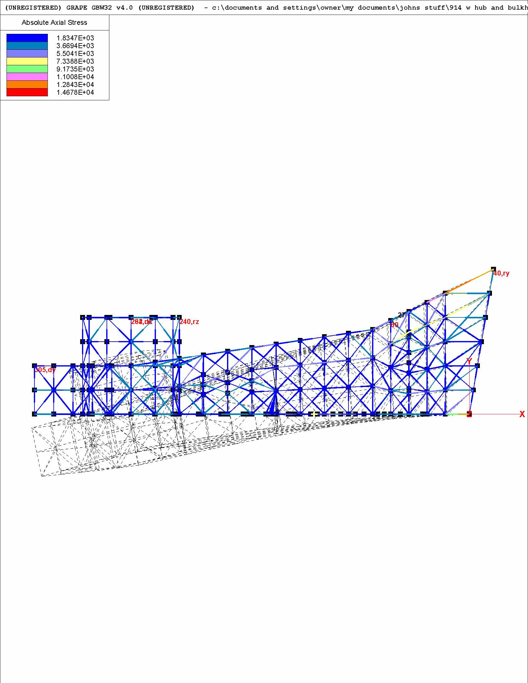
Here's pictural output of running the model with the hub and adding a bulkhead about half way down the length of the arm. I have not changed the force vectors yet in order to keep a consistent comparison between the different strategies that we're discussing. I'll post the data after I also run a separate model with a gusset and a floor combined. BTW, I've also updated the spreadsheet to translate the radians into degrees. Attached thumbnail(s) 
|
| jluetjen |
 Jan 9 2006, 12:06 PM Jan 9 2006, 12:06 PM
Post
#195
|
|
Member   Group: Members Posts: 53 Joined: 5-January 06 From: Westford, MA Member No.: 5,373 |
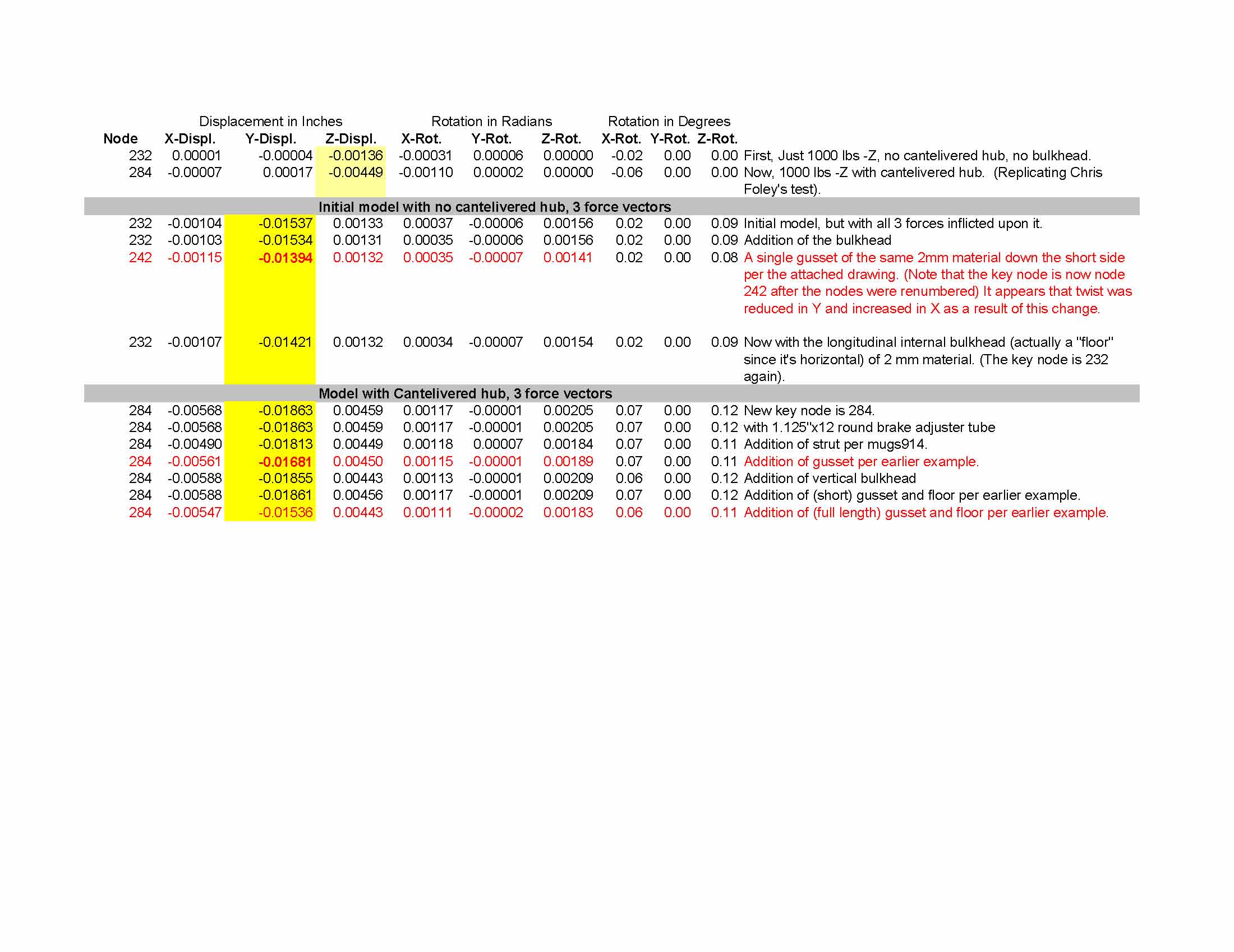
Here's the spreadsheet with the result of running the model with Chris's bulkhead included, and then with a floor (horizontal bulkhead) and external gusset both added. This last version seems to be the stiffest, but as a result increases the forces at the outer end of where the trailing arm attaches to the smaller tube -- where Chris has already attached some additional gussets. I'll explain the "short" and "long" gussets in the next reply.
Attached thumbnail(s) 
|
| jluetjen |
 Jan 9 2006, 12:22 PM Jan 9 2006, 12:22 PM
Post
#196
|
|
Member   Group: Members Posts: 53 Joined: 5-January 06 From: Westford, MA Member No.: 5,373 |
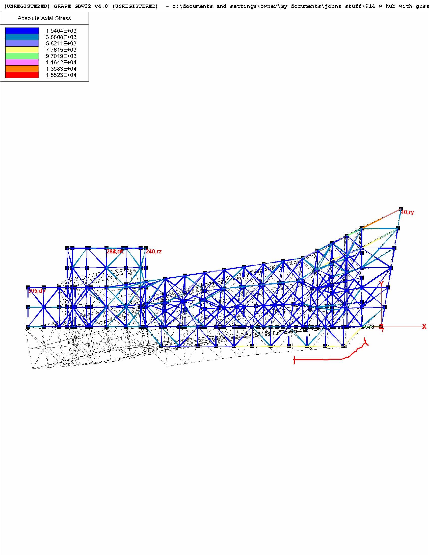
Here's the distortion top view and stresses for the model with an additional gusset as well as a "floor" which is essentially the gusset continued through to the other side of the arm. When I first made this update, I didn't include the portion next to the red line and was surprised to find that the results were marginally worse then the earlier example I had run with a gusset. Comparing the two models I noticed that I had stopped the gusset short of the full length. This is the "Short" gussetted model. When I added the gussetting next to the red line, the performance improved significantly -- and back to what I was expecting. I guess it just goes so show how sensitive some "small" changes in can be in relation to the model.
Attached thumbnail(s) 
|
| jluetjen |
 Jan 9 2006, 12:41 PM Jan 9 2006, 12:41 PM
Post
#197
|
|
Member   Group: Members Posts: 53 Joined: 5-January 06 From: Westford, MA Member No.: 5,373 |
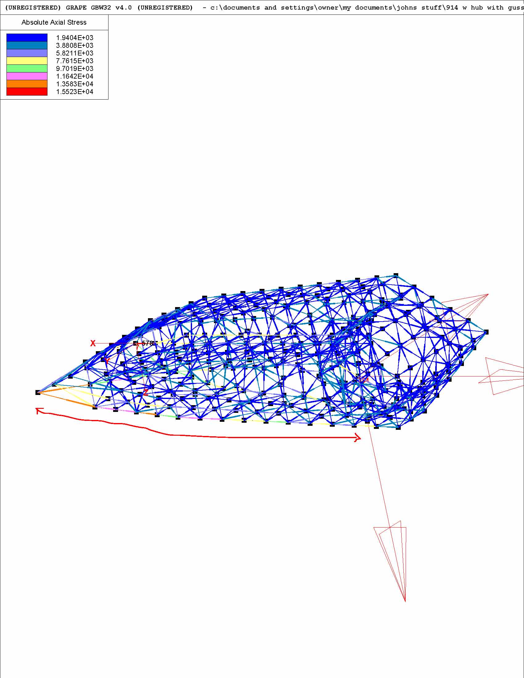
Here's a view of the same model from outside of the arm, so picture the hub is pointing towards your left shoulder. Note that the forces are now being channelled down the lower outside edge of the trailing arm, in addition to along the length of the gusset on the backside (in this picture).
|
| jluetjen |
 Jan 9 2006, 12:44 PM Jan 9 2006, 12:44 PM
Post
#198
|
|
Member   Group: Members Posts: 53 Joined: 5-January 06 From: Westford, MA Member No.: 5,373 |
Oops! Here's the attachment.
Attached thumbnail(s) 
|
| Downunderman |
 Jan 10 2006, 08:05 PM Jan 10 2006, 08:05 PM
Post
#199
|
|
Senior Member    Group: Members Posts: 852 Joined: 31-May 03 From: Sydney, Australia Member No.: 766 Region Association: Australia and New Zealand |
So after all of this clever stuff, is there a conclusion as to the best and lightest way to reinforce trailing arms? I have them sitting on the floor of my shed ready to start cutting and welding.
|
| ChicagoChris |
 Jan 10 2006, 09:07 PM Jan 10 2006, 09:07 PM
Post
#200
|
|
It was jack-stand-tastic!   Group: Members Posts: 168 Joined: 3-November 05 From: Chicago (burbs), IL Member No.: 5,062 |
I agree. I love watching you guys talk teck but when do you say "yes it works" and "it is lighter".
And if you wouldn't mind...a picture of what you put inside the arm would be handy. I get the bar on the leading edge. and that the outer triangle may have added strength to the corner but nothing measurable to the flex. But I seem to be missing what you put inside. |
  |
1 User(s) are reading this topic (1 Guests and 0 Anonymous Users)
0 Members:

|
Lo-Fi Version | Time is now: 14th December 2025 - 02:44 PM |
Invision Power Board
v9.1.4 © 2025 IPS, Inc.


