|
|

|
Porsche, and the Porsche crest are registered trademarks of Dr. Ing. h.c. F. Porsche AG.
This site is not affiliated with Porsche in any way. Its only purpose is to provide an online forum for car enthusiasts. All other trademarks are property of their respective owners. |
|
|
  |
| Thorshammer |
 Jan 10 2006, 09:17 PM Jan 10 2006, 09:17 PM
Post
#201
|
|
Senior Member    Group: Members Posts: 749 Joined: 11-November 03 Member No.: 1,335 |
Remember young whipper snappers, Measure twice cut once, or
Its done when I say its done. Or Shut the hell up I am thinking. All us back yard guys are just amazed at what we are seeingn here. My brain is hurting right now. Botomline is it what it is until we test it and proclaim it is better. But we really want to know why it is better. Erik Madsen |
| TimT |
 Jan 10 2006, 09:32 PM Jan 10 2006, 09:32 PM
Post
#202
|
|
retired     Group: Members Posts: 4,033 Joined: 18-February 03 From: Wantagh, NY Member No.: 313 |
You may have to "see" some things, you wont get blueprints to use. There is enough quality info and R&D here.
Chris knows what he is doing, John the nOOb (IMG:http://www.914world.com/bbs2/html/emoticons/wink.gif) is a whiz at FEA analysis.... |
| brant |
 Jan 10 2006, 10:56 PM Jan 10 2006, 10:56 PM
Post
#203
|
|
914 Wizard           Group: Members Posts: 11,926 Joined: 30-December 02 From: Colorado Member No.: 47 Region Association: Rocky Mountains 

|
I think people should send core arms to Chris to get the secret, "whats inside"
and I have to be honest here. More important than the stiffening, is the camber. I'm thinking that the camber (-negative I mean) is the genius break through here! good job chris! brant |
| ChrisFoley |
 Jan 12 2006, 09:35 PM Jan 12 2006, 09:35 PM
Post
#204
|
|
I am Tangerine Racing      Group: Members Posts: 7,980 Joined: 29-January 03 From: Bolton, CT Member No.: 209 Region Association: None 
|
Ok. I think I have a better handle on the mathematics of the forces at play here.
For simplicity I reduced the problem to two dimensions. Imagine a vertical plane, perpendicular to the direction of travel, containing the center point of the hub and the center point of the tire contact patch. Another important point is where the trailing arm axis intersects the plane. The contact patch is 7" outboard and 12" below the axis point. Two simultaneous forces occur during cornering, weight and cornering friction. The forces act on the axis point through the contact patch. At the contact patch the weight may reach about 1000lbs due to weight transfer. The cornering friction may be up to 1.5 times this amount - 1500lbs. Both forces can be split into two components - one pointing directly at the axis and the other perpendicular to the first - creating torque. The force components aiming directly at the axis can be further split into two components - horizontal and vertical - all pointing directly at the axis. The torque components of both forces have opposite direction so one partially cancels the other, leaving a net torque of 900 ft-lbs. The sum of the two vertical components works out to about 1400lbs. The sum of the two horizontal components works out to about 820 lbs. That's more than I expected for the lateral force. |
| ChrisFoley |
 Jan 12 2006, 09:50 PM Jan 12 2006, 09:50 PM
Post
#205
|
|
I am Tangerine Racing      Group: Members Posts: 7,980 Joined: 29-January 03 From: Bolton, CT Member No.: 209 Region Association: None 
|
QUOTE The contact patch is 7" outboard and 12" below the axis point. These numbers are approximately correct for a 9.5" slick on 7" rims. A narrower track width and taller tire will tend to increase the torque and decrease the lateral load, but lower grip will result in all the values being smaller anyway. |
| ChrisFoley |
 Jan 13 2006, 08:06 AM Jan 13 2006, 08:06 AM
Post
#206
|
|
I am Tangerine Racing      Group: Members Posts: 7,980 Joined: 29-January 03 From: Bolton, CT Member No.: 209 Region Association: None 
|
I came up with a simple way to fixture a trailing arm to my bench so I can test them using combined rotational and lateral loads.
Attached image(s) 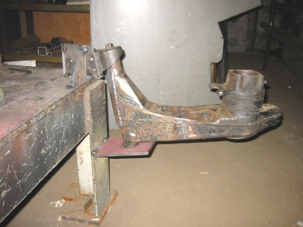
|
| jluetjen |
 Jan 13 2006, 08:38 AM Jan 13 2006, 08:38 AM
Post
#207
|
|
Member   Group: Members Posts: 53 Joined: 5-January 06 From: Westford, MA Member No.: 5,373 |
OK Folks. And now the moment that you've been waiting for -- Updated models with the forces moved out to the area of the contact patch. Some conclusions...
1) For the most part all of the displacements (aka: bending) got worse. The only exception was... 2) The model with the external gusset and internal floor. This model's output stayed the same (I double checked it too) and as a result was the best performing. Looking at the data, it even suggests that this model may channel the forces in such a way as to twist around the X-axis positively (increasing camber) by a small amount as opposed to twisting negatively. 3) This stuff is getting pretty computationally demanding. The base model runs almost instantaniously. The model with the bulkhead took about 1 minute, the model with the gusset kept my computer busy for 2 minutes, while the model with the bulkhead and floor took 3:48. Imagine doing that by hand! (IMG:http://www.914world.com/bbs2/html/emoticons/wacko.gif) Here's the data. Attached thumbnail(s) 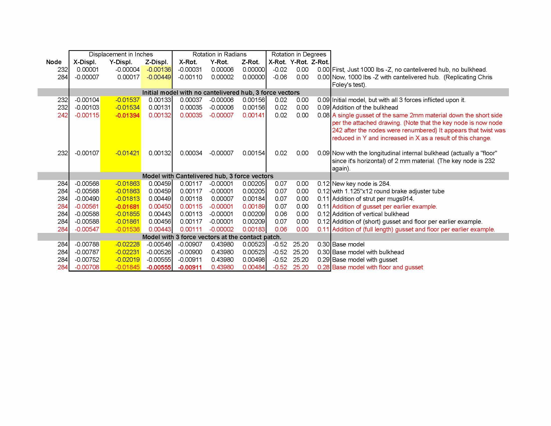
|
| jluetjen |
 Jan 13 2006, 08:44 AM Jan 13 2006, 08:44 AM
Post
#208
|
|
Member   Group: Members Posts: 53 Joined: 5-January 06 From: Westford, MA Member No.: 5,373 |
Here's how I set the models up. I used the geometry for a 3x3 inch solid steel beam, straight out from point 284 for 3 inches (a total of 7 inches from the X-axis), and 12 inches down. At that point (node 308 in this model) I applied the same 1000 lb forces as before (in order to remain consistent with the earlier data). So -1000 lbs X, -1000 lbs Y, and 1000 lbs Z.
Attached thumbnail(s) 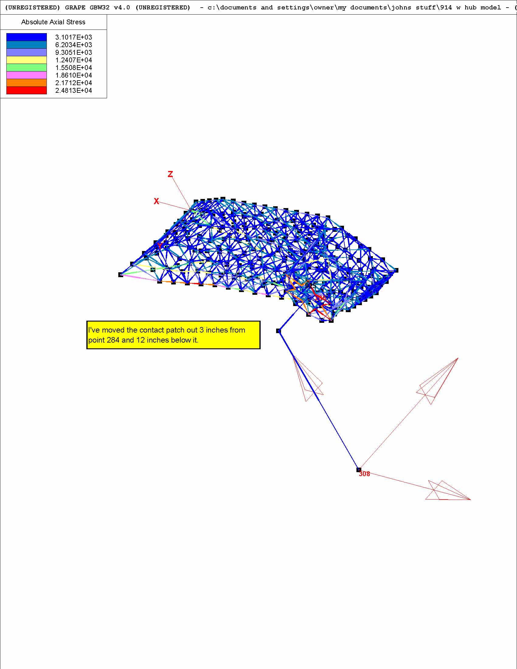
|
| jluetjen |
 Jan 13 2006, 08:46 AM Jan 13 2006, 08:46 AM
Post
#209
|
|
Member   Group: Members Posts: 53 Joined: 5-January 06 From: Westford, MA Member No.: 5,373 |
Here's the top view of the base model.
Attached thumbnail(s) 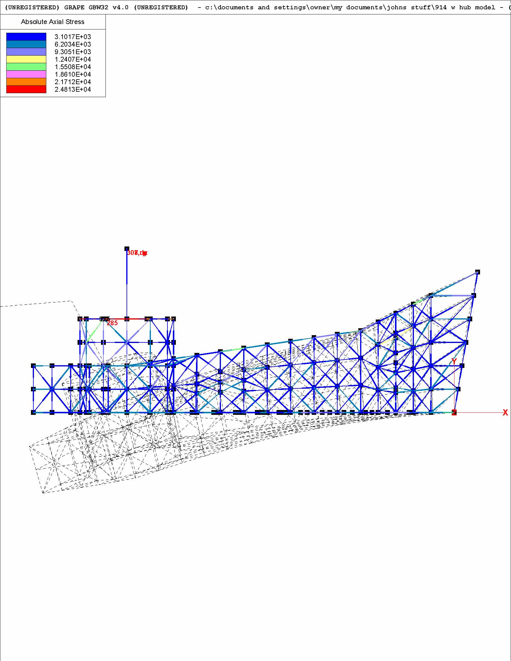
|
| jluetjen |
 Jan 13 2006, 08:47 AM Jan 13 2006, 08:47 AM
Post
#210
|
|
Member   Group: Members Posts: 53 Joined: 5-January 06 From: Westford, MA Member No.: 5,373 |
Here's the base model with the vertical bulkhead.
Attached thumbnail(s) 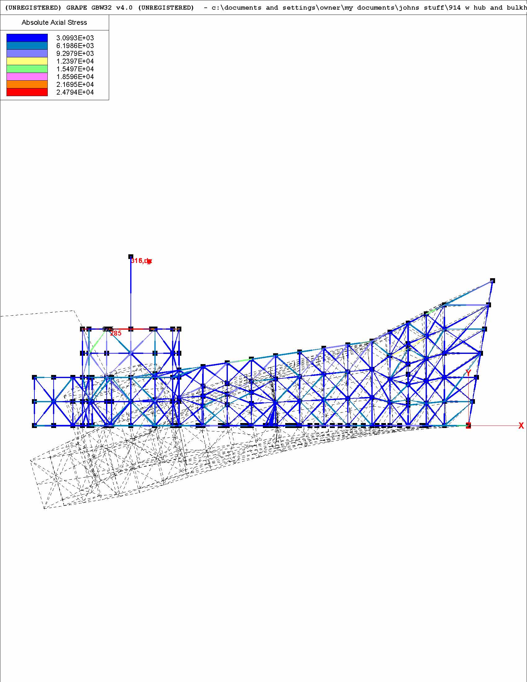
|
| jluetjen |
 Jan 13 2006, 08:48 AM Jan 13 2006, 08:48 AM
Post
#211
|
|
Member   Group: Members Posts: 53 Joined: 5-January 06 From: Westford, MA Member No.: 5,373 |
Here's the version with just the external gusset
Attached thumbnail(s) 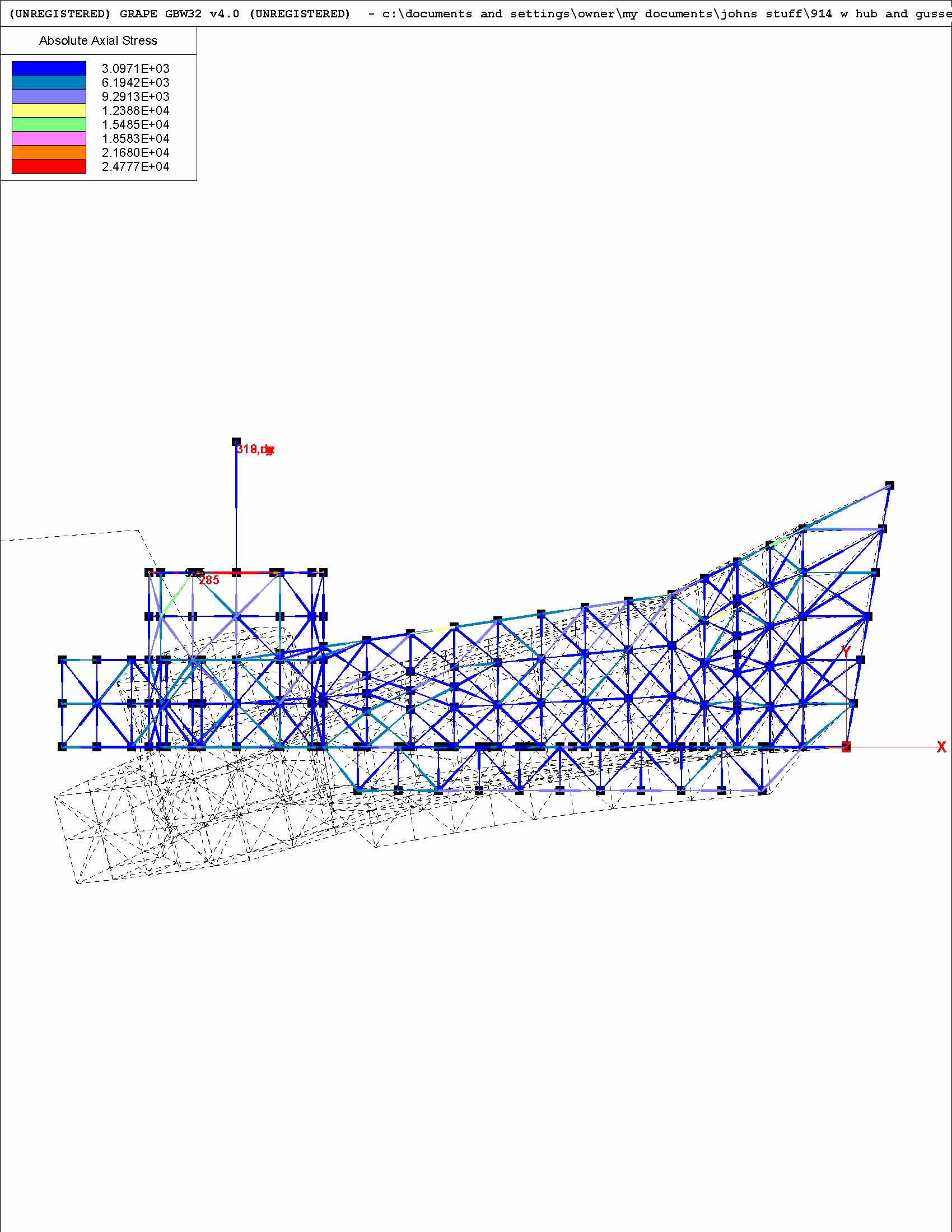
|
| jluetjen |
 Jan 13 2006, 08:50 AM Jan 13 2006, 08:50 AM
Post
#212
|
|
Member   Group: Members Posts: 53 Joined: 5-January 06 From: Westford, MA Member No.: 5,373 |
And finally the model with the external gusset and the floor added.
sigh.... (IMG:http://www.914world.com/bbs2/html/emoticons/givemebeer.gif) Attached thumbnail(s) 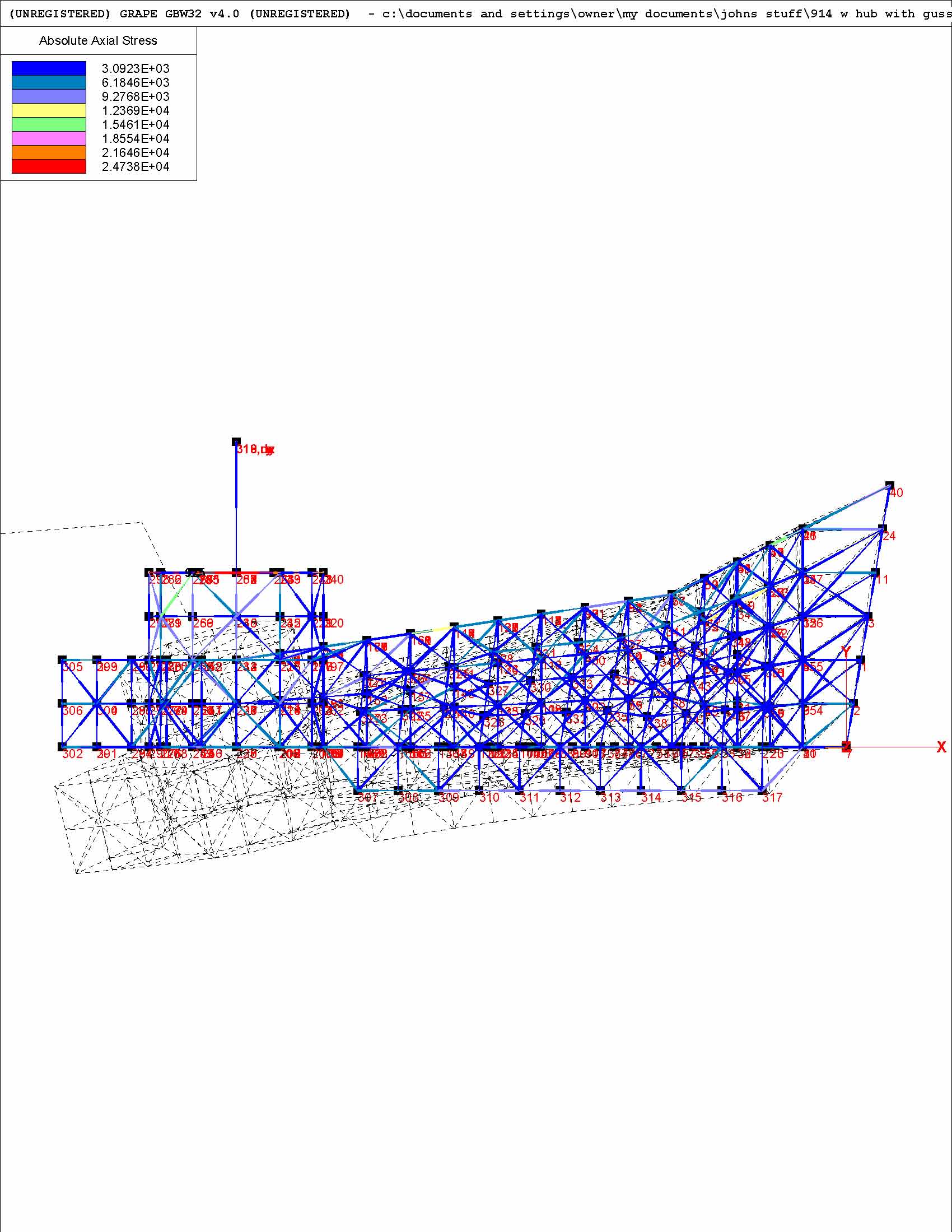
|
| jluetjen |
 Jan 13 2006, 08:52 AM Jan 13 2006, 08:52 AM
Post
#213
|
|
Member   Group: Members Posts: 53 Joined: 5-January 06 From: Westford, MA Member No.: 5,373 |
Now it's Chris's turn... (IMG:http://www.914world.com/bbs2/html/emoticons/welder.gif)
|
| ChrisFoley |
 Jan 16 2006, 09:17 AM Jan 16 2006, 09:17 AM
Post
#214
|
|
I am Tangerine Racing      Group: Members Posts: 7,980 Joined: 29-January 03 From: Bolton, CT Member No.: 209 Region Association: None 
|
I'm going to graphically show how I arrived at the force numbers I posted above.
Point A represents a point along the twisting (longitudinal) axis of the trailing arm. Point B represents the center of the tire contact patch. I estimated the center of the tire to be offset 7" outboard of the axis, and 12" below. The distance between the points is 13.8". The ground is pushing up on the tire with a force of about 1000lb. At 1.5G the sideways force exerted on the tire contact patch is about 1500lb. Attached image(s) 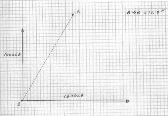
|
| ChrisFoley |
 Jan 16 2006, 09:20 AM Jan 16 2006, 09:20 AM
Post
#215
|
|
I am Tangerine Racing      Group: Members Posts: 7,980 Joined: 29-January 03 From: Bolton, CT Member No.: 209 Region Association: None 
|
Working with just the sideways force for a moment, I can separate that into two vector components. One points directly at point A and the other is perpendicular to the line segment A-B.
Attached image(s) 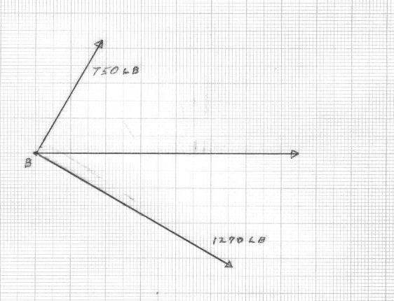
|
| ChrisFoley |
 Jan 16 2006, 09:22 AM Jan 16 2006, 09:22 AM
Post
#216
|
|
I am Tangerine Racing      Group: Members Posts: 7,980 Joined: 29-January 03 From: Bolton, CT Member No.: 209 Region Association: None 
|
Doing the same thing for the vertical force yields this graph. Notice the perpendicular component points the opposite direction from the previous graph.
Attached image(s) 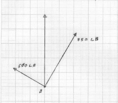
|
| ChrisFoley |
 Jan 16 2006, 09:24 AM Jan 16 2006, 09:24 AM
Post
#217
|
|
I am Tangerine Racing      Group: Members Posts: 7,980 Joined: 29-January 03 From: Bolton, CT Member No.: 209 Region Association: None 
|
Now both sets of force vectors are shown simultaneously.
Attached image(s) 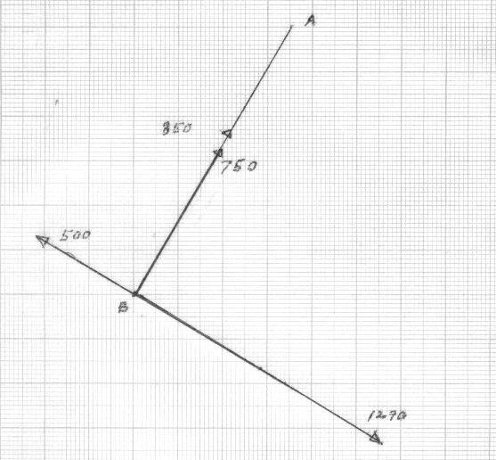
|
| ChrisFoley |
 Jan 16 2006, 09:26 AM Jan 16 2006, 09:26 AM
Post
#218
|
|
I am Tangerine Racing      Group: Members Posts: 7,980 Joined: 29-January 03 From: Bolton, CT Member No.: 209 Region Association: None 
|
Performing simple vector addition yields this graph.
A force of 1600 lb is aimed directly at Point A, and a force of 790 lb is perpendicular - twisting the trailing arm. Attached image(s) 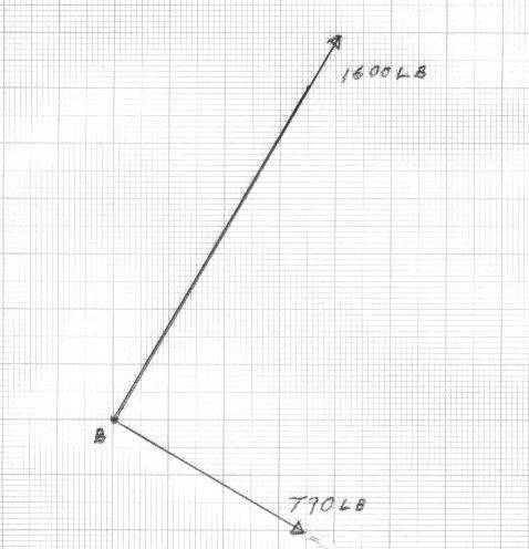
|
| ChrisFoley |
 Jan 16 2006, 09:28 AM Jan 16 2006, 09:28 AM
Post
#219
|
|
I am Tangerine Racing      Group: Members Posts: 7,980 Joined: 29-January 03 From: Bolton, CT Member No.: 209 Region Association: None 
|
Working only with the force vector directed at point A I can further split that into a vertical and a horizontal component. Since that force is aimed directly at A I moved the origin to point A.
Attached image(s) 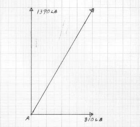
|
| ChrisFoley |
 Jan 16 2006, 09:34 AM Jan 16 2006, 09:34 AM
Post
#220
|
|
I am Tangerine Racing      Group: Members Posts: 7,980 Joined: 29-January 03 From: Bolton, CT Member No.: 209 Region Association: None 
|
Since the perpendicular force vector is 13.8" from Point A it exerts a torque of 910 ft-lbs.
Attached image(s) 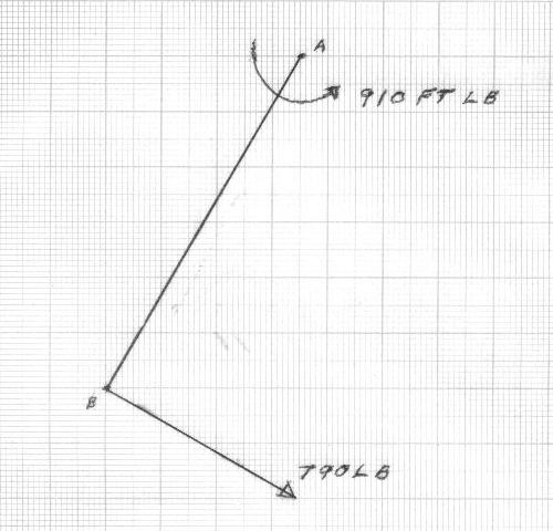
|
  |
2 User(s) are reading this topic (2 Guests and 0 Anonymous Users)
0 Members:

|
Lo-Fi Version | Time is now: 3rd April 2025 - 06:07 PM |
Invision Power Board
v9.1.4 © 2025 IPS, Inc.


