|
|

|
Porsche, and the Porsche crest are registered trademarks of Dr. Ing. h.c. F. Porsche AG.
This site is not affiliated with Porsche in any way. Its only purpose is to provide an online forum for car enthusiasts. All other trademarks are property of their respective owners. |
|
|
  |
| ChrisFoley |
 Jan 16 2006, 09:38 AM Jan 16 2006, 09:38 AM
Post
#221
|
|
I am Tangerine Racing      Group: Members Posts: 7,980 Joined: 29-January 03 From: Bolton, CT Member No.: 209 Region Association: None 
|
Now graphing everything simultaneously it can be seen that the two forces acting on the tire contact patch can be studied as three forces acting directly on the trailing arm at a point along the longitudinal twisting axis.
1) a vertical force pushing up on the trailing arm of 1390 lb. 2) a horizontal force of 810 lb trying to bend the trailing arm laterally. 3) a torque of 910 ft-lb trying to twist the trailing arm. Attached image(s) 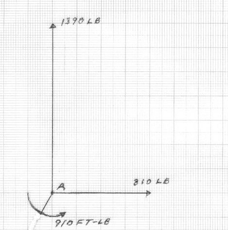
|
| ChrisFoley |
 Jan 16 2006, 09:39 AM Jan 16 2006, 09:39 AM
Post
#222
|
|
I am Tangerine Racing      Group: Members Posts: 7,980 Joined: 29-January 03 From: Bolton, CT Member No.: 209 Region Association: None 
|
Any questions? (IMG:style_emoticons/default/cool_shades.gif)
|
| jluetjen |
 Jan 16 2006, 03:38 PM Jan 16 2006, 03:38 PM
Post
#223
|
|
Member   Group: Members Posts: 53 Joined: 5-January 06 From: Westford, MA Member No.: 5,373 |
Wow -- I started having flashbacks to high-school math!
One question now that you've done all the math.... By just moving the application of the forces out to the contact patch like I did in the last round of models (based on your input -- thank you!) did I do essentially the same thing? In a couple of days I'll try modeling your forces directly on the arm and see if it results in similar outputs to what I go by moving the forces. (BTW -- I've got no internet until tomorrow some time thanks to a tree that fell over yesterday morning in the high winds. On the way to the ground the tree also snapped off a utility pole at ground level and yanked all of the wires to our house. (IMG:http://www.914world.com/bbs2/html/emoticons/WTF.gif) ) |
| TravisNeff |
 Jan 16 2006, 04:35 PM Jan 16 2006, 04:35 PM
Post
#224
|
||
|
914 Guru      Group: Members Posts: 5,082 Joined: 20-March 03 From: Mesa, AZ Member No.: 447 Region Association: Southwest Region 
|
when do you get started for external customers? (IMG:http://www.914world.com/bbs2/html/emoticons/wink.gif) |
||
| ChrisFoley |
 Jan 16 2006, 04:40 PM Jan 16 2006, 04:40 PM
Post
#225
|
||
|
I am Tangerine Racing      Group: Members Posts: 7,980 Joined: 29-January 03 From: Bolton, CT Member No.: 209 Region Association: None 
|
You moved the force application point outboard too far. You added 7" from point 284 but it should be 7" from the approximate centerline of the box. Otherwise you did the same thing. |
||
| ChrisFoley |
 Jan 16 2006, 04:44 PM Jan 16 2006, 04:44 PM
Post
#226
|
|
I am Tangerine Racing      Group: Members Posts: 7,980 Joined: 29-January 03 From: Bolton, CT Member No.: 209 Region Association: None 
|
QUOTE My best estimate is sometime in the spring. I still need a proper fixture to hold the trailing arms. |
| ChrisFoley |
 Jan 16 2006, 04:49 PM Jan 16 2006, 04:49 PM
Post
#227
|
|
I am Tangerine Racing      Group: Members Posts: 7,980 Joined: 29-January 03 From: Bolton, CT Member No.: 209 Region Association: None 
|
QUOTE Wow -- I started having flashbacks to high-school math! Once I actually sat down and started working on the problem it turned out to be fairly simple. I think, even adding the 3rd dimension wouldn't be too complicated, but a bit tough on a sheet of graph paper. QUOTE I've got no internet until tomorrow I hope you at least have electricity tonight. |
| Brett W |
 Jan 16 2006, 06:41 PM Jan 16 2006, 06:41 PM
Post
#228
|
|
Advanced Member     Group: Members Posts: 2,858 Joined: 17-September 03 From: huntsville, al Member No.: 1,169 Region Association: None 
|
Can someone please resize the images? (IMG:http://www.914world.com/bbs2/html/emoticons/mad.gif)
|
| ChrisFoley |
 Jan 16 2006, 08:35 PM Jan 16 2006, 08:35 PM
Post
#229
|
||
|
I am Tangerine Racing      Group: Members Posts: 7,980 Joined: 29-January 03 From: Bolton, CT Member No.: 209 Region Association: None 
|
We're not done quite yet. I'm pretty happy with the results of my 3 piece reinforcement but the tests aren't complete. Hang in there. (IMG:http://www.914world.com/bbs2/html/emoticons/smile.gif) |
||
| pek771 |
 Jan 16 2006, 08:53 PM Jan 16 2006, 08:53 PM
Post
#230
|
|
Member   Group: Members Posts: 275 Joined: 23-November 05 From: Conover, NC Member No.: 5,175 Region Association: None 
|
Chris is pretty close on this. I thought about it while I applied Dry-Lok to the basement walls today.
My crude treatment has a twisting force of 1142 ft-lb, not counting any sway bar, and without constraint from the shock absorber laterally. This is using the 13.8" and 7", with the 1500# side load and 1000" vertical load. I did not use any of the acute angle deviations from the normal axes, as would be encountered in a real trailing arm, but I believe were incorporated in the Chris and John stuff. If I could upload my scratch paper from the scanner, I'd post it. Chris and John did a very masterful job on this real world engineering problem, in case anyone had any doubts. Pat |
| jluetjen |
 Jan 17 2006, 04:58 PM Jan 17 2006, 04:58 PM
Post
#231
|
|
Member   Group: Members Posts: 53 Joined: 5-January 06 From: Westford, MA Member No.: 5,373 |
Comcast came to the house and we're back in business today.
OK. I've gone back and updated my earlier postings with revised outputs reflecting the contact patch being only about 3 inches outside of node 284. The results are similar to the earlier outputs. The big difference is that by reducing the distance out from the center from 11 inches to 7, we actually increased the twisting (torque force) some. Playing with Chris's vector math will show why. |
| ChrisFoley |
 Jan 18 2006, 06:56 AM Jan 18 2006, 06:56 AM
Post
#232
|
|
I am Tangerine Racing      Group: Members Posts: 7,980 Joined: 29-January 03 From: Bolton, CT Member No.: 209 Region Association: None 
|
Thanks John!
Looking at the data - It appears that the Y displacements are all around 20 thousandths of an inch. The corresponding rotation is 25 degrees? If you measured the angular change of the surface at node 284 (X direction in the X-Z plane) I think it would be quite small. The Z displacements are all around 5 thousandths with a corresponding rotation of 0.5 degrees. At least that is in the same order of magnitude as the real world experiments. Do these rotations correspond with the angular change (Z direction in the X-Z plane) of the surface at node 284? The angular change of this surface is what should closely follow my data if the model is believable. I am surprised (disappointed) that the model doesn't reflect the improvement I see from adding the bulkhead. There must be something going on in the real world that the model doesn't reflect. It looks like there are some nodes near the outer pickup point that have very high stress levels. This corresponds with the earlier comment about cracks in the pivot tube near this location. |
| jluetjen |
 Jan 18 2006, 07:40 AM Jan 18 2006, 07:40 AM
Post
#233
|
|
Member   Group: Members Posts: 53 Joined: 5-January 06 From: Westford, MA Member No.: 5,373 |
Chris; Good catch about the magnitude of the y-rotation. It's not real clear to me how that manifests itself in the real world short of the hub trying to twist itself off of the arm under braking. As I mentioned, I really haven't modelled the hub that accurately since it should be modeled as a solid piece of metal as opposed to being fabricated sheet metal. This definitely gives me an appreciation for the stress that a hub has to deal with.
Here's a couple of different views of the 3 primary models -- the base model, the model with the vertical bulkhead and the model with the gusset and floor. In this case you are looking down the arm. The X and Z rotation is much clearer in the animation rather then just the distortion plot. Does anyone have any ideas on how to capture the "movie" off of my screen and post it? First the base model Attached thumbnail(s) 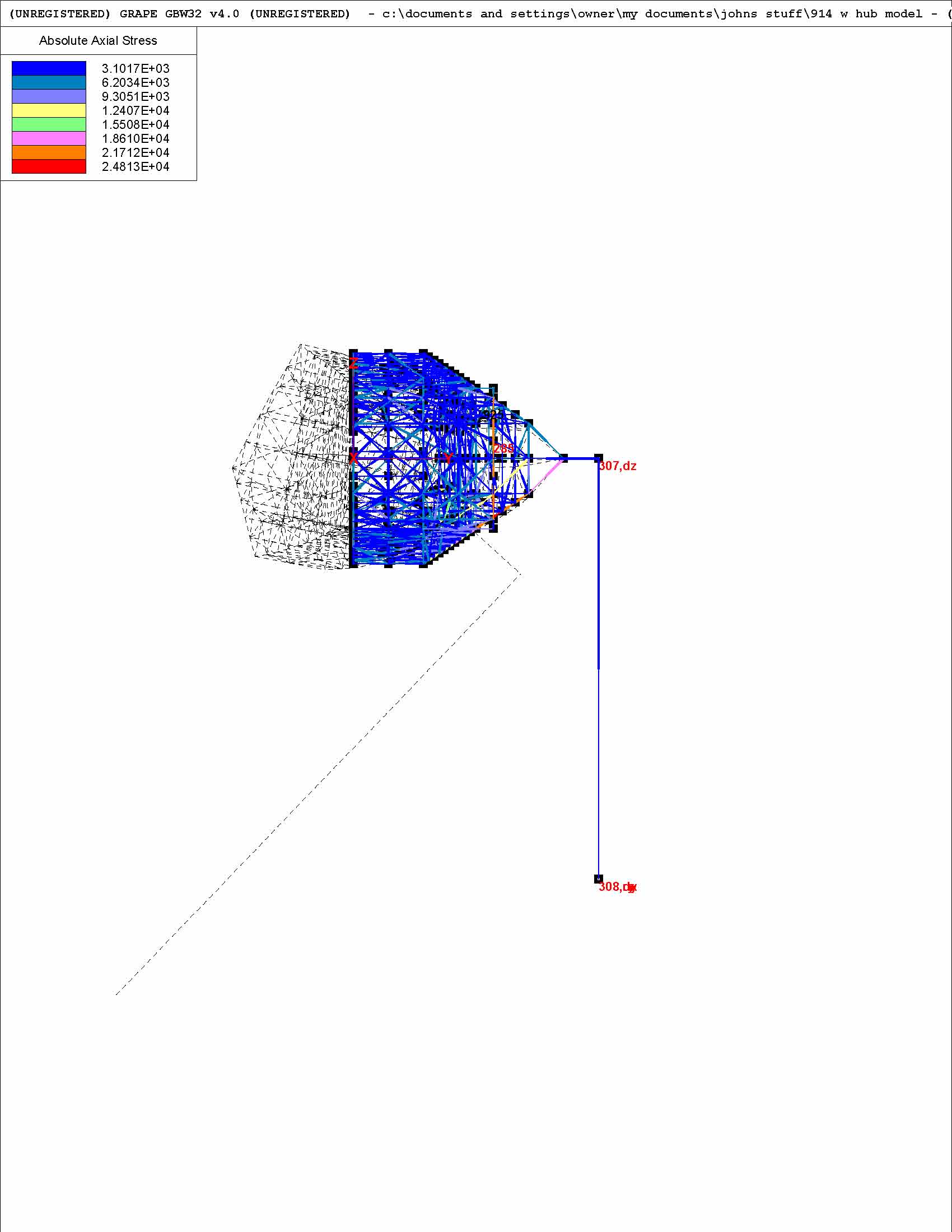
|
| jluetjen |
 Jan 18 2006, 07:45 AM Jan 18 2006, 07:45 AM
Post
#234
|
|
Member   Group: Members Posts: 53 Joined: 5-January 06 From: Westford, MA Member No.: 5,373 |
This is the model with the bulkhead.
Attached thumbnail(s) 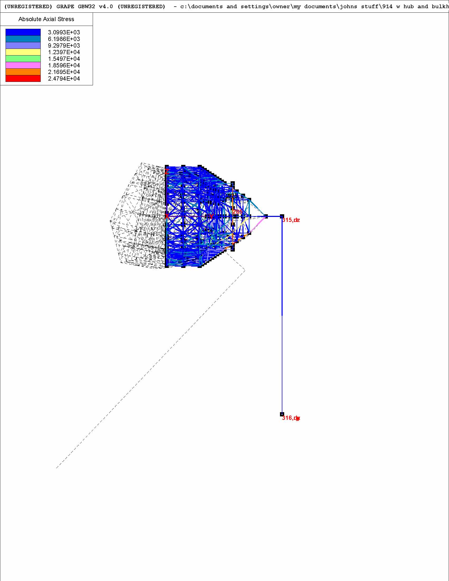
|
| jluetjen |
 Jan 18 2006, 07:46 AM Jan 18 2006, 07:46 AM
Post
#235
|
|
Member   Group: Members Posts: 53 Joined: 5-January 06 From: Westford, MA Member No.: 5,373 |
And the model with the gusset and floor.
Attached thumbnail(s) 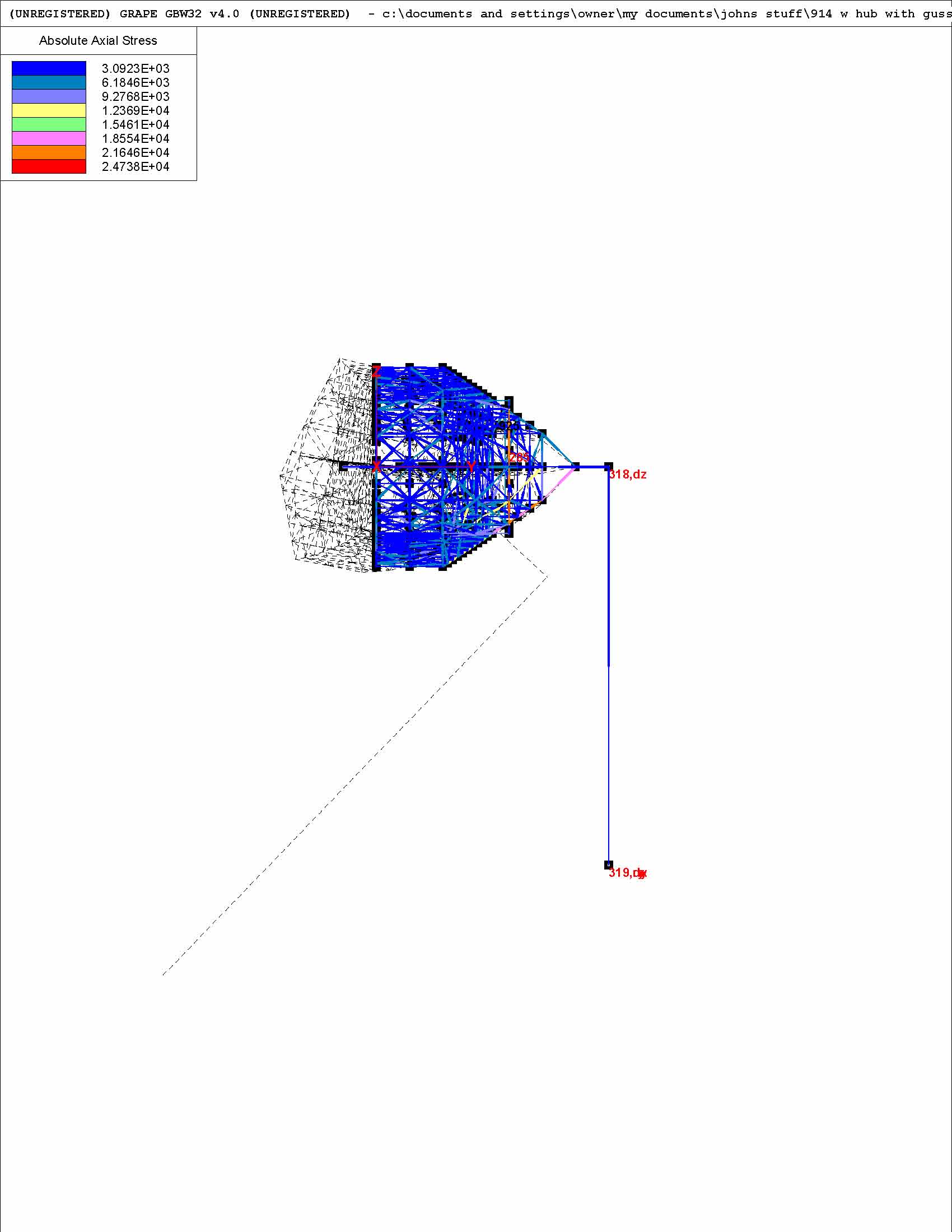
|
| jluetjen |
 Jan 18 2006, 07:55 AM Jan 18 2006, 07:55 AM
Post
#236
|
|
Member   Group: Members Posts: 53 Joined: 5-January 06 From: Westford, MA Member No.: 5,373 |
Here's a different view that may be helpful to understand the Y-Rotation issue. Note the very high stresses in a star pattern at the hub. I believe that this is the result of node 284 trying to spin (torque around) and thus add a lot of stress to those elements that make up the web in that area.
Attached thumbnail(s) 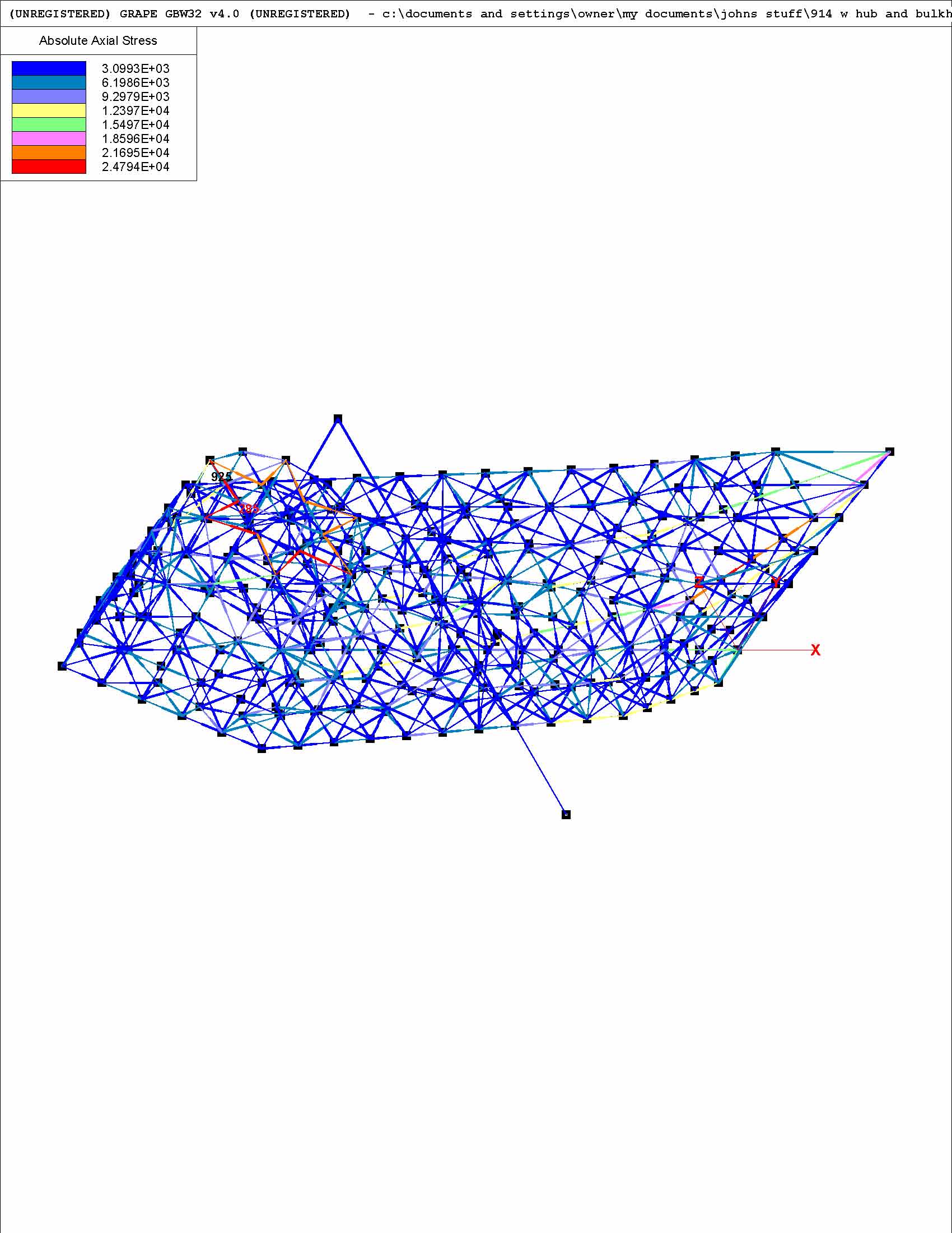
|
| ChrisFoley |
 Jan 18 2006, 09:30 AM Jan 18 2006, 09:30 AM
Post
#237
|
|
I am Tangerine Racing      Group: Members Posts: 7,980 Joined: 29-January 03 From: Bolton, CT Member No.: 209 Region Association: None 
|
John,
It is apparent that the "arm" you added to move the forces out to the contact patch also is bending at node 284. Using the values I computed can you apply the loads directly to node 284, ignoring the braking force. You will have to calculate the appropriate force to equal 900 ft-lbs torque for the vertical (down) load. |
| jluetjen |
 Jan 18 2006, 01:00 PM Jan 18 2006, 01:00 PM
Post
#238
|
|
Member   Group: Members Posts: 53 Joined: 5-January 06 From: Westford, MA Member No.: 5,373 |
Chris;
The software only allows me to add forces in the X, Y and Z direction. There's no place to add torques. Would you agree that as a result I should be adding 1390 lb vertically in addition to (910 * 12 / 7 inches = ) 1560 lbs vertically to equal 2950 lbs vertically? And then the 810 lbs horizontally. Does this sound right? |
| ChrisFoley |
 Jan 18 2006, 05:00 PM Jan 18 2006, 05:00 PM
Post
#239
|
|
I am Tangerine Racing      Group: Members Posts: 7,980 Joined: 29-January 03 From: Bolton, CT Member No.: 209 Region Association: None 
|
QUOTE Does this sound right? Not exactly. The 1390 is in the opposite direction and is not aimed at node 284. I think it could be ignored, since it shouldn't cause any bending or twisting. If included it needs to aim at a point on the twisting axis (imaginary line between the shock absorber mount and somewhere along the pivot shaft) parallel to node 284. The 910 is foot pounds. If node 284 is only 3 inches from the twisting axis you need to multiply the force by 4 to get the same torque effect. |
| jluetjen |
 Jan 18 2006, 05:11 PM Jan 18 2006, 05:11 PM
Post
#240
|
||||
|
Member   Group: Members Posts: 53 Joined: 5-January 06 From: Westford, MA Member No.: 5,373 |
Duh! (IMG:http://www.914world.com/bbs2/html/emoticons/unsure.gif) I wasn't thinking right. Let me try again. As far as ignoring the twisting forces -- I'm not there. Maybe I'll stick on a cone so that the point is about 12 inches from the axis and then apply the 910 lb-feet there. (IMG:http://www.914world.com/bbs2/html/emoticons/idea.gif) |
||||
  |
1 User(s) are reading this topic (1 Guests and 0 Anonymous Users)
0 Members:

|
Lo-Fi Version | Time is now: 3rd April 2025 - 06:07 PM |
Invision Power Board
v9.1.4 © 2025 IPS, Inc.


