|
|

|
Porsche, and the Porsche crest are registered trademarks of Dr. Ing. h.c. F. Porsche AG.
This site is not affiliated with Porsche in any way. Its only purpose is to provide an online forum for car enthusiasts. All other trademarks are property of their respective owners. |
|
|
  |
| ChrisFoley |
 Jan 18 2006, 06:53 PM Jan 18 2006, 06:53 PM
Post
#241
|
|
I am Tangerine Racing      Group: Members Posts: 8,018 Joined: 29-January 03 From: Bolton, CT Member No.: 209 Region Association: None 
|
QUOTE As far as ignoring the twisting forces -- I'm not there. I'm not suggesting ignoring any twisting forces. The 1390lb vertical up is the component that pushes straight into the trailing arm. It is the part of the "weight" that does not exert ANY twisting force. If you want to include it, break it up and apply it at several nodes on the bottom the trailing arm That would eliminate any point loading. All the twisting force is included in the 910 ft lb. What's wrong with multiplying the torque by the fraction of a foot node 284 is from the axis? This eliminates any extraneous structure that might deform under the load. My last graph shows all the forces being applied at what I labeled point A (an imaginary point on the longitudinal axis of the trailing arm). You just need to figure out how far node 284 is from the axis. The horizontal force can be applied at node 284 since that is in a direct line with the axis, as viewed from the side. |
| ChrisFoley |
 Jan 18 2006, 07:12 PM Jan 18 2006, 07:12 PM
Post
#242
|
|
I am Tangerine Racing      Group: Members Posts: 8,018 Joined: 29-January 03 From: Bolton, CT Member No.: 209 Region Association: None 
|
Maybe this will help.
Imagine that all three arrows I drew are in the same plane as node 284. The vertical up arrow needs to be a force of 1390lb. The horizontal arrow needs to be a force of 810lb. The vertical down arrow needs to be a force of 3600lb!!! That's right. It is only 3 inches from the centerline of the trailing arm box. Attached image(s) 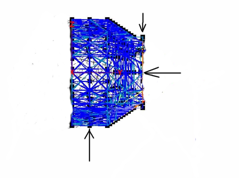
|
| jluetjen |
 Jan 19 2006, 07:43 AM Jan 19 2006, 07:43 AM
Post
#243
|
|
Member   Group: Members Posts: 53 Joined: 5-January 06 From: Westford, MA Member No.: 5,373 |
OK. Here you go -- although I fear that we might be going down a "rat hole" with this approach. The reason is that I fear that we're trying to kluge the computations which are already inherent in the model. At the end of the day I don't believe that it really tells us any more, but could very well confuse us more. Kind of like if you wear one watch -- you're always pretty sure what time it is, but if you wear two watches you'll never know what time it is. In this case we'll get another set of numbers, but since they ignore braking and other lateral forces -- of course they'll be different.
The picture below is looking at the arm from behind the shock mount and is a little busier then normal to show what was done. Forces: Per Chris's diagram above. Constraints: Both front pivots are constrained in all three directions -- X, Y and Z. So those points won't move. I had to constrain the shock mount in the vertical (Z) direction to keep the model from flying all over the place. I'm kind of concerned about his since this constraint is only a couple of inches away from where we're applying the vertical forces. Essentially I'm concerned that I'm over constraining the model. Results: The model is still bending along it's length. While I follow Chris's vector math, I don't believe the way that the forces are being applied to the arm accurately reflect the environment the arm is in. For example, the arm never sees a positive Z force at the bottom of the arm -- but our model has such a force. So we're essentially solving a problem that doesn't exist from a mathematical perspective. I think a better way to cross check the model and help develop a test methodology would be to do the vector math as of point 284. Basically do the math so that the answer results in a single torque being applied at point 284. This answer can then be used to mount a beam at a given angle from X/Y/Z which Chris can then fabricate and test with. I'll try giving it a shot later today. Attached thumbnail(s) 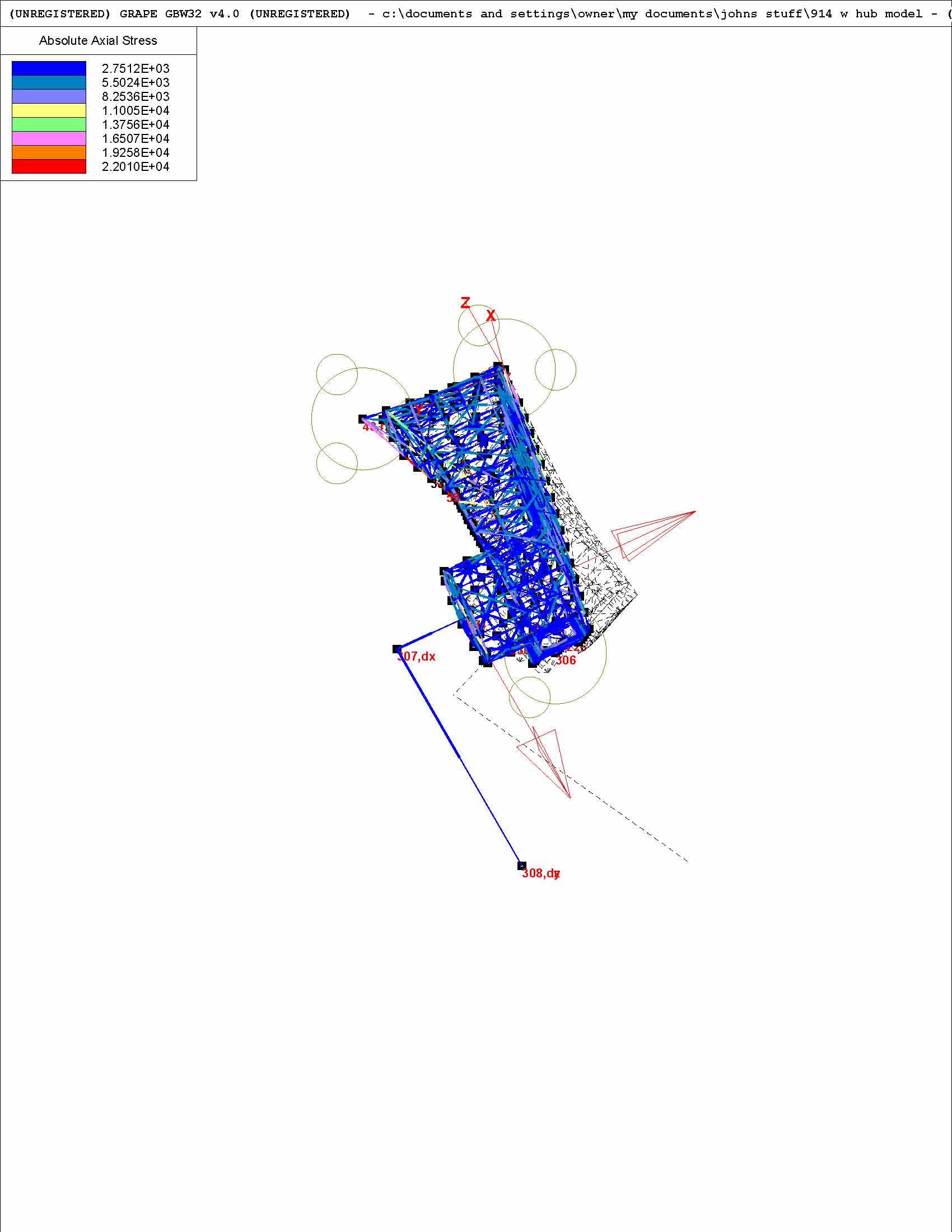
|
| jluetjen |
 Jan 19 2006, 07:54 AM Jan 19 2006, 07:54 AM
Post
#244
|
|
Member   Group: Members Posts: 53 Joined: 5-January 06 From: Westford, MA Member No.: 5,373 |
And one more view that reflects Chris's mark-up above.
Attached thumbnail(s) 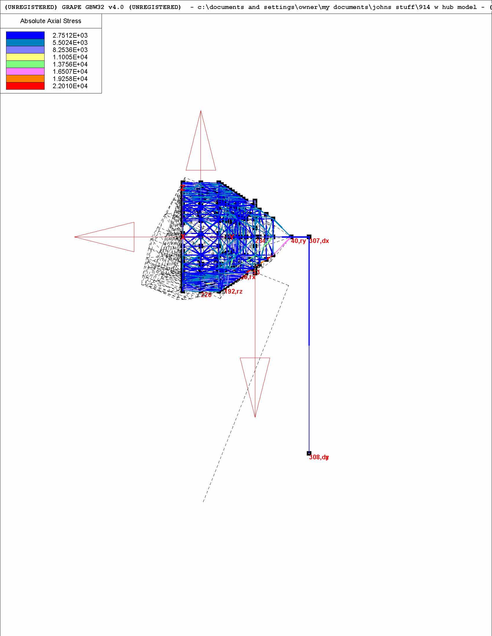
|
| ChrisFoley |
 Jan 19 2006, 08:02 AM Jan 19 2006, 08:02 AM
Post
#245
|
|
I am Tangerine Racing      Group: Members Posts: 8,018 Joined: 29-January 03 From: Bolton, CT Member No.: 209 Region Association: None 
|
Here's the updated data table resized to fit.
Attached image(s) 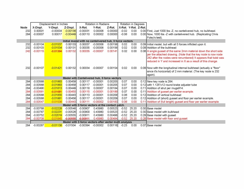
|
| ChrisFoley |
 Jan 19 2006, 08:31 AM Jan 19 2006, 08:31 AM
Post
#246
|
|
I am Tangerine Racing      Group: Members Posts: 8,018 Joined: 29-January 03 From: Bolton, CT Member No.: 209 Region Association: None 
|
QUOTE OK. Here you go -- I like what I see now. I do still have a couple of minor issues: 1) Can you reduce the displaced skeleton view to 10x instead of 100x. I think that it over-dramatizes the situation currently. 2) I want the outboard pivot location moved closer to node 284. The pivot axis properly should be perpendicular to the inner box surface. The distance of node 284 from the pivot axis will be approximately correct with this change. 3) I'm picking nits now, but - since the arm is mounted to the car with the pivot axis at a 12.5 degreee angle the tube connecting node 284 should be at such an angle, the lateral force should also be at the same angle, and the vertical up force should be moved forward a corresponding amount. These changes would satisfy me that we have modeled a trailing arm as well as GRAPE can do for us within reason. QUOTE ... but since they ignore braking and other lateral forces -- QUOTE ... the arm never sees a positive Z force at the bottom of the arm... QUOTE ... do the math so that the answer results in a single torque being applied at point 284. |
| Brett W |
 Jan 19 2006, 08:38 AM Jan 19 2006, 08:38 AM
Post
#247
|
|
Advanced Member     Group: Members Posts: 2,859 Joined: 17-September 03 From: huntsville, al Member No.: 1,169 Region Association: None 
|
One thing to keep in mind is the shocks will provide no lateral location of the trailing arm. So restraining the shock mount will provide no usable data.
|
| ChrisFoley |
 Jan 19 2006, 08:45 AM Jan 19 2006, 08:45 AM
Post
#248
|
|
I am Tangerine Racing      Group: Members Posts: 8,018 Joined: 29-January 03 From: Bolton, CT Member No.: 209 Region Association: None 
|
One last point for now, the rotations listed in the table don't accurately reflect the real world. I don't think this means the model isn't accurate, only that the point about which the rotations occur isn't modeled accurately. If possible, it would be better to tabulate the angular change (in 2 axes) of the surface that node 284 is at the center of.
QUOTE the shocks will provide no lateral location of the trailing arm |
| jluetjen |
 Jan 19 2006, 09:12 AM Jan 19 2006, 09:12 AM
Post
#249
|
||||
|
Member   Group: Members Posts: 53 Joined: 5-January 06 From: Westford, MA Member No.: 5,373 |
Chris!!! Now you're "gilding lillies". (IMG:http://www.914world.com/bbs2/html/emoticons/rolleyes.gif) How is any of this going to change the strategy that you use for modifying the trailing arm? |
||||
| Brett W |
 Jan 19 2006, 10:19 AM Jan 19 2006, 10:19 AM
Post
#250
|
|
Advanced Member     Group: Members Posts: 2,859 Joined: 17-September 03 From: huntsville, al Member No.: 1,169 Region Association: None 
|
Duh! My bad, I should have read closer. (IMG:http://www.914world.com/bbs2/html/emoticons/chair.gif)
|
| ChrisFoley |
 Jan 19 2006, 04:59 PM Jan 19 2006, 04:59 PM
Post
#251
|
|
I am Tangerine Racing      Group: Members Posts: 8,018 Joined: 29-January 03 From: Bolton, CT Member No.: 209 Region Association: None 
|
QUOTE Chris!!! Now you're "gilding lillies". How is any of this going to change the strategy that you use for modifying the trailing arm? LOL! I can ask can't I? (IMG:style_emoticons/default/biggrin.gif) Actually, I expect that moving the outer pickup rearward, and inputing the lateral force at 12.5 degrees will have a noticeable (I don't know how significant though) effect on the data output from the model. As long as I'm asking for the moon, I would also love to see the effect of the lateral force by itself, and the torque force by itself. John, can you explain what calculation is used to produce the rotation numbers in the table? Do you have control over that calculation? |
| jluetjen |
 Jan 19 2006, 05:50 PM Jan 19 2006, 05:50 PM
Post
#252
|
||||||||
|
Member   Group: Members Posts: 53 Joined: 5-January 06 From: Westford, MA Member No.: 5,373 |
Actually, the front pick-ups are aligned correctly against the body of the arm. The rear hub assembly was not offset by an angle -- so that's the angle that is not reflected. Moving that back by ~6 degrees is not going to make a huge difference since the large diameter tube that the hub is attached to connects to the arm across a wide area.
How do I say this nicely?.... No.
Dammit Chris! I'm a salesman -- not a mathematician. That means I was smart enough to recruit to my team (aka: marry) an engineer with a master's degree who grunted through 6 years of advanced college level math rather then take the classes myself. The other thing that I learned in B-School (in addition to strategic acqusitions) is delegation. I just emailed to you a copy of the software and the base model. (IMG:http://www.914world.com/bbs2/html/emoticons/pissoff.gif) BTW: Grape is Shareware that can be downloaded from the Grape Software web page. |
||||||||
| jluetjen |
 Jan 19 2006, 06:23 PM Jan 19 2006, 06:23 PM
Post
#253
|
|
Member   Group: Members Posts: 53 Joined: 5-January 06 From: Westford, MA Member No.: 5,373 |
Oh yeah, here's the latest data table. Note that the rough order of incremental improvement for each strategy is consistent even as we change different force strategies. To my simple mind this suggests that the results will be fairly consistent even if you change an angle here or a few pounds there.
Attached thumbnail(s) 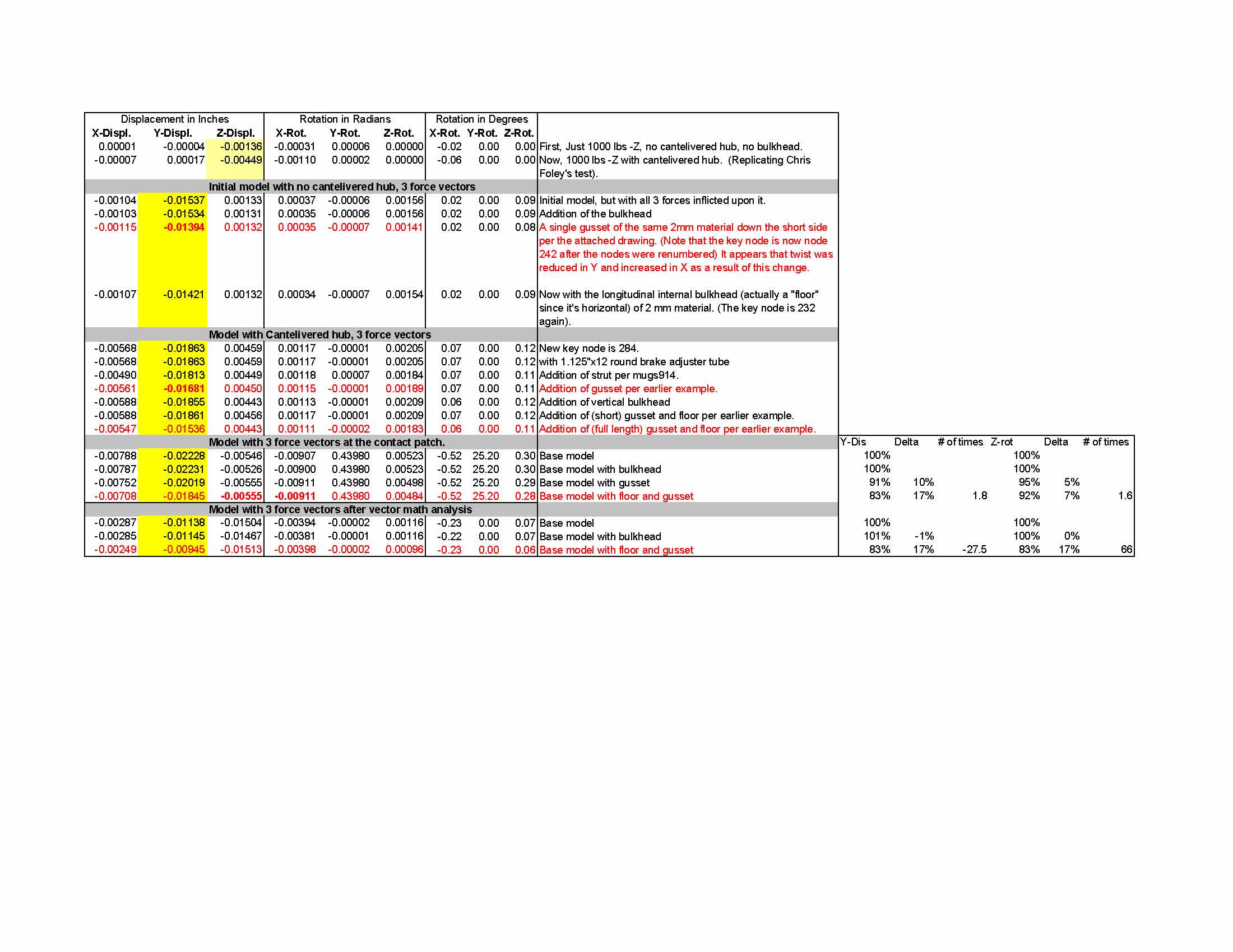
|
| ChrisFoley |
 Jan 19 2006, 08:48 PM Jan 19 2006, 08:48 PM
Post
#254
|
|
I am Tangerine Racing      Group: Members Posts: 8,018 Joined: 29-January 03 From: Bolton, CT Member No.: 209 Region Association: None 
|
QUOTE Actually, the front pick-ups are aligned correctly against the body of the arm. Hold a carpenter's square against the inside face of the box section and you will see what I am getting at. John, for a salesman you make a pretty good engineer. I have been impressed with the depth you go into this sort of analysis. I really appreciate all you have done and I will find a way to repay the favor down the road. 0 I'll see if I can pick up where you left off on the model (unless I can get Tim to do it (IMG:style_emoticons/default/biggrin.gif) ). Thanks!! |
| jluetjen |
 Jan 20 2006, 09:09 AM Jan 20 2006, 09:09 AM
Post
#255
|
||||||||
|
Member   Group: Members Posts: 53 Joined: 5-January 06 From: Westford, MA Member No.: 5,373 |
Ok -- I've been thinking that we're starting to "lose the forest for the trees". This is going to be a real challenge -- I'm going to try to be brief. (IMG:http://www.914world.com/bbs2/html/emoticons/clap.gif)
Using FAE to figure out if the answer is 0.00498 versus 0.00484 is most likely not an effective use of the tool. If you want to know the meaning of life -- it's 42. (IMG:http://www.914world.com/bbs2/html/emoticons/WTF.gif) But what is the question??? To answer that I went back 243 posts to look at where we started and found these thoughts:
and...
and...
and finally this fairly pithy problem statement:
((IMG:http://www.914world.com/bbs2/html/emoticons/yawn.gif) If you want to jump to my proposal and skip the long winded monologue, it's at the bottom.) What we've learned along the way since they consisentanly came out in our tests and model -- no matter what we did to them. 1) The stock arm does flex. 2) Adding an internal bulkhead stiffens it some. 3) Adding an external gusset stiffens it more. 4) Combining the two approaches stiffens it even more 5) There are some concentrated stresses in the hub area (where Porsche's designers kindly designed in a fairly massive piece) and where the arm attaches to the outer end of the front pivot tube. Some things that we already knew 1) Weight is evil 2) Stiffness increases with the cross sectional area and to a lesser degree by filling in internal voids. Putting these factors all together I modified the spreadsheet to take into account the extra material being added by each solution (assuming it's all 2mm thick steel) and then compared this to the reduction in Y-displacement and Z-Rotation (which both impact toe). I then tried to optomise the solution some based on the earlier approaches and rather then combining the external gusset with an internal "floor", I tried triangulating the top edge of the gusset to the corners of the arm's original box section. The result? A solution that is stiffer then all of the previous options, but uses less material then the next stiffest option. But even though, the best "stiffness versus weight gain" option remains the original simple external gusset. My Final Recommendations! 1) For the lightest solution, weld a lengthwise external gusset to the arm. 2) For the strongest solution, weld additional pieces from the exposed edge of the gusset down to the arm, thus creating a "peaked roof" type of structure. No matter what you do, doubling the thickness of the material in the area near the outer half of the front pivot tube will essentially cut the surface stresses in that area by half (same stress, double the material) which is a good thing. Now back to my day job! (IMG:http://www.914world.com/bbs2/html/emoticons/wavey.gif) Attached image(s) 
|
||||||||
| jluetjen |
 Jan 20 2006, 09:11 AM Jan 20 2006, 09:11 AM
Post
#256
|
|
Member   Group: Members Posts: 53 Joined: 5-January 06 From: Westford, MA Member No.: 5,373 |
Here's the overhead view of the gusset with the "peaked roof" results.
Attached thumbnail(s) 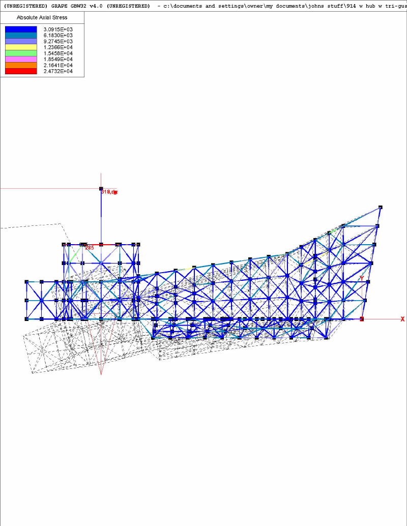
|
| jluetjen |
 Jan 20 2006, 09:17 AM Jan 20 2006, 09:17 AM
Post
#257
|
|
Member   Group: Members Posts: 53 Joined: 5-January 06 From: Westford, MA Member No.: 5,373 |
A view from the outside of the arm (when mounted) showing the area of highest stresses.
Attached thumbnail(s) 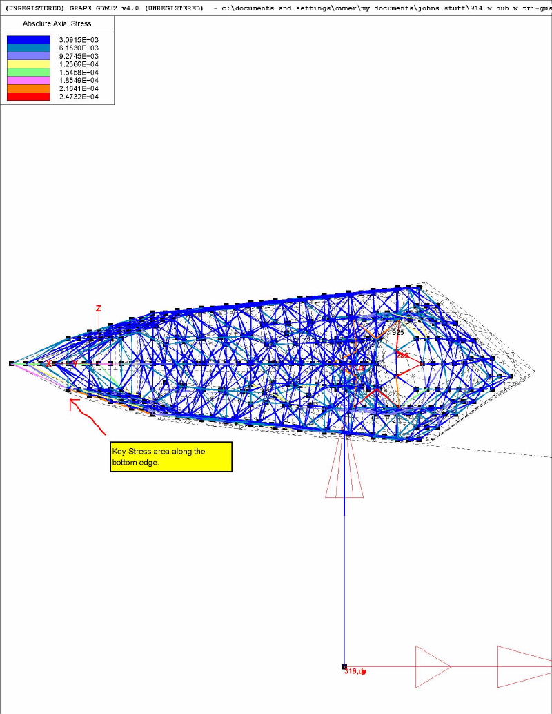
|
| jluetjen |
 Jan 20 2006, 09:18 AM Jan 20 2006, 09:18 AM
Post
#258
|
|
Member   Group: Members Posts: 53 Joined: 5-January 06 From: Westford, MA Member No.: 5,373 |
Finally an "edge on" view showing the "peaked roof" structure that I discussed showed the best stiffness improvement.
Attached thumbnail(s) 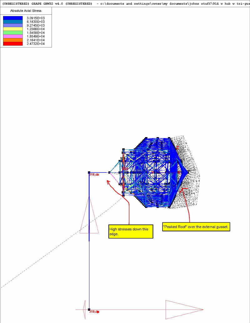
|
  |
1 User(s) are reading this topic (1 Guests and 0 Anonymous Users)
0 Members:

|
Lo-Fi Version | Time is now: 12th January 2026 - 07:01 PM |
Invision Power Board
v9.1.4 © 2026 IPS, Inc.


