|
|
|
Porsche, and the Porsche crest are registered trademarks of Dr. Ing. h.c. F. Porsche AG.
This site is not affiliated with Porsche in any way. Its only purpose is to provide an online forum for car enthusiasts. All other trademarks are property of their respective owners. |
|
|

  |

| dan10101 |
 Sep 1 2003, 11:12 AM Sep 1 2003, 11:12 AM
Post
#21
|
|
TORQUE-o-holic  Group: Members Posts: 1,140 Joined: 29-April 03 From: Eagle Point, Or Member No.: 626 Region Association: Pacific Northwest |
I forgot my main point. His throttle body doesn't have a fitting. It's just a blank. You can kinda see it in the picture above.
|
   |

 
|
| Bleyseng |
Sep 1 2003, 11:15 AM
Post
#22
|
|
Aircooled Baby! Group: Members Posts: 13,035 Joined: 27-December 02 From: Seattle, Washington (for now) Member No.: 24 Region Association: Pacific Northwest |
It plugs into the throttle body only on 73 throttle bodies. On later cars Porsche plugged or didn't install the port on the Throttle body. You can install a port to install the vacuum advance hose. This helps the engine have alittle more umph at lower rpms.
If its not there just leave the hose hanging off the dizzy. Geoff |
|
|
|
| dan10101 |
Sep 1 2003, 11:26 AM
Post
#23
|
|
TORQUE-o-holic Group: Members Posts: 1,140 Joined: 29-April 03 From: Eagle Point, Or Member No.: 626 Region Association: Pacific Northwest |
Ya, this FI came from a 75 I think. So one of our projects down the road will be to drill for the advance. Probably a smog thing.
Any other gotchas we need to worry about on using a later FI? For those who didn't know. We bought this car with Weber 34s. Andrew decided to go back to stock. |
|
|
|
| Andyrew |
Sep 1 2003, 11:54 AM
Post
#24
|
|
Spooling.... Please wait Group: Members Posts: 13,376 Joined: 20-January 03 From: Riverbank, Ca Member No.: 172 Region Association: Northern California |
QUOTE For those who didn't know. We bought this car with Weber 34s. Andrew decided to go back to stock. You say that like its a bad thing. I wanted a little more than 60 hp.. give me the 90 stock hp. Geof, thanks for all your helpful info, it will all help a whole heck of alot. Thanks, Andrew |
|
|
|
| Bleyseng |
Sep 1 2003, 02:25 PM
Post
#25
|
|
Aircooled Baby! Group: Members Posts: 13,035 Joined: 27-December 02 From: Seattle, Washington (for now) Member No.: 24 Region Association: Pacific Northwest |
Match the ECU, MPS, and the CHT if they don't you will have some minor problems like crappy idle or the worst case- too lean and drop valve seats.
What are the #'s?? Geoff |
|
|
|
| dan10101 |
Sep 1 2003, 03:11 PM
Post
#26
|
|
TORQUE-o-holic Group: Members Posts: 1,140 Joined: 29-April 03 From: Eagle Point, Or Member No.: 626 Region Association: Pacific Northwest |
Everything came off the same car. ECU, MPS, (what's a CHT?), But basically, it's off the same car. We're using the distributor from the 73 2.0 and the relay board off the 73 and that's about it. That brings me to the next questions.
How do these wires hook up to the distributor? Only one was hooked up when we had it running. Attached image(s) 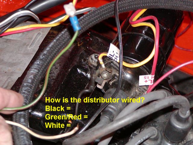
|
|
|
|
| dan10101 |
Sep 1 2003, 03:12 PM
Post
#27
|
|
TORQUE-o-holic Group: Members Posts: 1,140 Joined: 29-April 03 From: Eagle Point, Or Member No.: 626 Region Association: Pacific Northwest |
The next question (probably not the last) has to do with these wires to the relay board. The red wire comes from the alternator and the green/red wire are cut and are on the harness under the relay board.
Attached image(s) 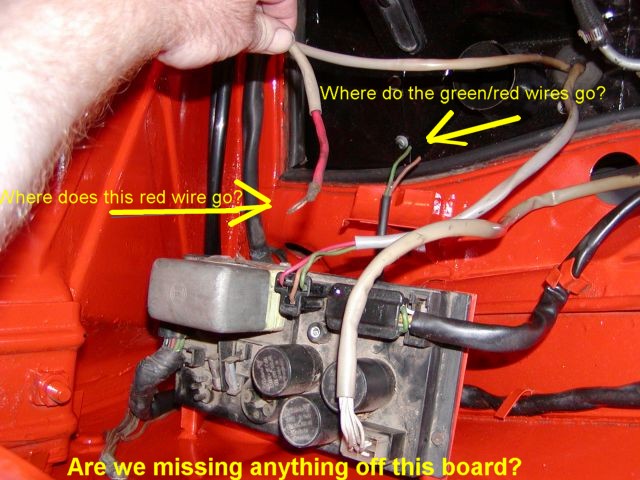
|
|
|
|
| dan10101 |
Sep 1 2003, 04:56 PM
Post
#28
|
|
TORQUE-o-holic Group: Members Posts: 1,140 Joined: 29-April 03 From: Eagle Point, Or Member No.: 626 Region Association: Pacific Northwest |
Well, we figured out from the wiring diagram that the red wire goes to the starter. Still working on the gr/rd wire...
The distributor has a smaller black wire, apparently the big black wire goes to the neg side of the coil and the small black wire goes to the positive side of the coil. The green/red wire goes to the oil sending unit?? White ?? Ahh, CHT, Cylinder head temp. May need to order one of these to match the 75 system. That was one of the things that didn't come with the system we bought. Sorry for all the questions, but we really appreciate all the help.. Thanks all! (IMG:style_emoticons/default/smilie_pokal.gif) |
|
|
|
| dan10101 |
Sep 1 2003, 05:00 PM
Post
#29
|
|
TORQUE-o-holic Group: Members Posts: 1,140 Joined: 29-April 03 From: Eagle Point, Or Member No.: 626 Region Association: Pacific Northwest |
QUOTE(dan10101 @ Sep 1 2003, 02:56 PM) White ?? Looks like the white wire goes to the Supplimentary air valve. Is that the same as the AAR valve? |
|
|
|
| Bleyseng |
Sep 1 2003, 05:27 PM
Post
#30
|
|
Aircooled Baby! Group: Members Posts: 13,035 Joined: 27-December 02 From: Seattle, Washington (for now) Member No.: 24 Region Association: Pacific Northwest |
The red/green should be the heater fan booster.
The white wire should go to the AAR valve. |
|
|
|
| dan10101 |
Sep 1 2003, 11:46 PM
Post
#31
|
|
TORQUE-o-holic Group: Members Posts: 1,140 Joined: 29-April 03 From: Eagle Point, Or Member No.: 626 Region Association: Pacific Northwest |
Well time is ticking down and we're not done. I guess we'll just get a 50cal machine gun and fill it full of lead. (IMG:style_emoticons/default/ohmy.gif)
Misfits Maybe not. (IMG:style_emoticons/default/smile.gif) We got a lot done, but the factory fuel lines were plugged solid. We need to run some replacements. Plus the brake calipers didn't arrive yet and that will keep the Junior in HS from driving his Porsche to the first day of school. Oh well, we're a LOT further than if we didn't attempt it. Maybe by the weekend. Thanks for all the help, Especially Geoff!!! |
|
|
|
| Bleyseng |
Sep 2 2003, 05:53 AM
Post
#32
|
|
Aircooled Baby! Group: Members Posts: 13,035 Joined: 27-December 02 From: Seattle, Washington (for now) Member No.: 24 Region Association: Pacific Northwest |
try 100 lbs of air on those lines to clean them out, worked for me.
Geoff |
|
|
|
| Dave_Darling |
Sep 2 2003, 05:06 PM
Post
#33
|
|
914 Idiot Group: Members Posts: 15,003 Joined: 9-January 03 From: Silicon Valley / Kailua-Kona Member No.: 121 Region Association: Northern California |
The first pic, those wires appear to all be in the "engine wiring harness". That is the one that plugs into the 12-pin connector on the right-rear of the relay board. There should be a somewhat-thick black wire that connects to coil (+) and supplies +12V when the ignition switch is on. There should also be a thinner black/purple wire (the purple fades and can be tough to see) that connects to the coil (-) terminal and is the tach signal wire. The green/red hooks up to the oil light sender just aft of the distributor. And the white one hooks to the AAR (yes, supplemental air valve is another name for it).
The other wires are all alternator-related. The alternator should have four wires coming from it. One harness with red, green, and black wires, and a separate big thick red wire. You've already found that the thick red wire goes to the starter, same terminal that the fat cable from the battery fits on. (That's the primary charging path, alt->starter->batt.) The other three wires connect to the relay board by a plug. Looks like you have the plug on your board but the harness was cut. [EDIT!] Oh, uh... Nope! On second look, those two wires in the second pic are the two wires to the heater blower motor. That would live in the left-front corner of the engine bay on a metal stand on 73+ cars. 70-72 1.7s had the blower in the middle on a bracket bolted to the engine fan housing. --DD |
|
|
|
| dan10101 |
Sep 2 2003, 11:56 PM
Post
#34
|
|
TORQUE-o-holic Group: Members Posts: 1,140 Joined: 29-April 03 From: Eagle Point, Or Member No.: 626 Region Association: Pacific Northwest |
Day 8 - Jesse would have blown this one up for sure. Thank goodness we have a bit more patience.
Well we tried 100psi and it worked for the large tube, but the small one is just too gummed up to be used. Tried jamming a coathanger down there and still wouldnt' budge, It's now history. Have a couple of brake lines per Pelican tech tip. We'll Monster up a fuel system and get it running soon. (after he POR15s the channel). DaveD, Right on brother... (IMG:style_emoticons/default/blink.gif) Just confirmed everything I was guessing,. Except I guessed wrong on the big and little black wire, and I couldn't find the oil sending unit because our new breather hose was hiding it. All is well wiring wise. (except for a couple wierd ones under the car...Hmmm) WWIT (while we're in there), we decided it would be a good time to install the front sway bar since the fuel tank is out. Not sure how it mounts on the inside. The top two bolts seem fine, but the bottom one goes thru a double wall about 1.5" deep. Is that normal? Just use a long bolt? The picts I've seen show a notch cut out for the bottom bolt. Andyrew, (do I have to call you that on this board?) Can you post that picture you found? |
|
|
|
| Andyrew |
Sep 3 2003, 12:07 AM
Post
#35
|
|
Spooling.... Please wait Group: Members Posts: 13,376 Joined: 20-January 03 From: Riverbank, Ca Member No.: 172 Region Association: Northern California |
Here is how andy did it.. I am guessing this is the accepted way of practice since I am also guessing it was done at brads shop..
(IMG:http://www.sirandy.com/pix/914/2003.04.17/IMGP1729.jpg) Just cruzin through andy's pics and saw it.. Andrew |
|
|
|
| Bleyseng |
Sep 3 2003, 08:33 AM
Post
#36
|
|
Aircooled Baby! Group: Members Posts: 13,035 Joined: 27-December 02 From: Seattle, Washington (for now) Member No.: 24 Region Association: Pacific Northwest |
Thats how you install the front sway bar if the car doesn't have the factory mount.
Geoff |
|
|
|
| dan10101 |
Sep 4 2003, 11:40 PM
Post
#37
|
|
TORQUE-o-holic Group: Members Posts: 1,140 Joined: 29-April 03 From: Eagle Point, Or Member No.: 626 Region Association: Pacific Northwest |
Does anyone have a picture of the factory sway bar from the fuel tank side?
I've seen a few from the wheel well side. Andy spent the big bucks and bought aftermarket... |
|
|
|
| Brad Roberts |
Sep 4 2003, 11:45 PM
Post
#38
|
|
914 Freak! Group: Members Posts: 19,148 Joined: 23-December 02 Member No.: 8 Region Association: None |
They are done the same way... the bottom bolt is hidden (Nuts welded to chassis).
B |
|
|
|
| dan10101 |
Sep 4 2003, 11:47 PM
Post
#39
|
|
TORQUE-o-holic Group: Members Posts: 1,140 Joined: 29-April 03 From: Eagle Point, Or Member No.: 626 Region Association: Pacific Northwest |
Ok, day hmmm. must be about 10 by now..
Pistons came in from sunny Florida yesterday. The only problem is they were surrounded by these UGLY calipers. We spend hours trying everything to get them out. Finally got one out and were releved to find it in good condition. (we thought they would be pitted to death). Spend a couple more hours tonight. Then it dawned on me. Cut the suckers in half! So we did. 45 mins later they were all out. We cut until we were within a few mm of breaking through. Then hammered them apart. Worked like a charm. Attached image(s) 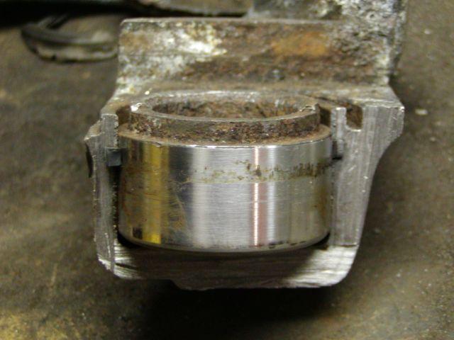
|
|
|
|
| dan10101 |
Sep 4 2003, 11:50 PM
Post
#40
|
|
TORQUE-o-holic Group: Members Posts: 1,140 Joined: 29-April 03 From: Eagle Point, Or Member No.: 626 Region Association: Pacific Northwest |
QUOTE(Brad Roberts @ Sep 4 2003, 09:45 PM) They are done the same way... the bottom bolt is hidden (Nuts welded to chassis). B So, there is not a plate on the inside. Just 3 bolt holes and the large hole acording to the template. I suppose we can cut a notch like Andy did to put a bolt on the bottom. Thanks Brad. |
|
|
|
|
2 User(s) are reading this topic (2 Guests and 0 Anonymous Users)
0 Members:

|
Lo-Fi Version | Time is now: 7th July 2024 - 06:23 AM |
Invision Power Board
v9.1.4 © 2024 IPS, Inc.