|
|

|
Porsche, and the Porsche crest are registered trademarks of Dr. Ing. h.c. F. Porsche AG.
This site is not affiliated with Porsche in any way. Its only purpose is to provide an online forum for car enthusiasts. All other trademarks are property of their respective owners. |
|
|
  |
| ClayPerrine |
 Apr 30 2006, 09:03 PM Apr 30 2006, 09:03 PM
Post
#1
|
|
Life's been good to me so far.....                Group: Admin Posts: 16,224 Joined: 11-September 03 From: Hurst, TX. Member No.: 1,143 Region Association: NineFourteenerVille 
|
BOSCH D-JETRONIC
MANIFOLD PRESSURE CONTROL SYSTEM (MPC) Mercedes-Benz: 280, 300, 350, 450 Porsche: 914 Saab: 99E Volkswagen: Type 3 & 4 Volvo: 1800E, 1800ES, 142, 144, 164E DESCRIPTION The Bosch D-Jetronic electronic fuel injection system is composed of 3 major subsystems: the air intake system, the fuel system, and the electronic control system. The D-Jetronic system uses constant fuel pressure and flow, so that only injection duration needs to be modified to control air/fuel mixture. The D-Jetronic system measures incoming airflow by monitoring intake manifold pressure. Engine speed, temperature, and other factors are monitored for the purpose of fine-tuning injection duration. An auxiliary air valve, cold start injector and thermotime switch aid in cold starting and operation. OPERATION FUEL SYSTEM An electrically driven fuel pump forces fuel through a filter, into the main system. Main system consists of one injector for each cylinder, a cold start injector and a pressure regulator, which maintains fuel pressure at 28 psi (2.0 kg/cm2). A secondary system carries excess fuel from the pressure regulator back to fuel tank. 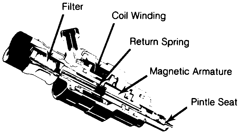 Fig. 1: Sectional View of Fuel Injector 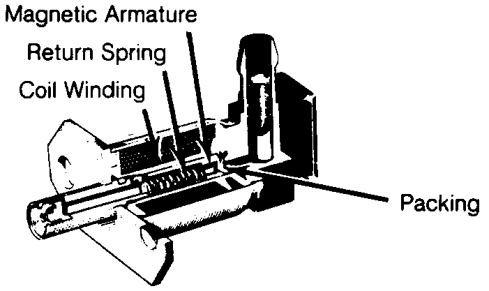 Fig. 2: Sectional View of Cold Start Injector AIR SYSTEM Intake manifold, connected to an intake air distributor, supplies the cylinders with air. A pressure sensor is connected to intake air distributor. The pressure sensor operates according to difference in manifold pressure and atmospheric pressure and signals control unit accordingly. A throttle valve, operated by accelerator pedal, is located at the mouth of the intake air distributor. The throttle valve and intake air distributor are connected to air cleaner by an air duct elbow. The idling air system is in the form of a by-pass system located between the air filter and air intake distributor. Its size can be varied with an idling air adjusting screw. An auxiliary air line, from air cleaner (auxiliary air valve), to intake air distributor forms the warming-up air system. Its volume is varied, depending on engine temperature, by the auxiliary air valve. ELECTRONIC CONTROL SYSTEM Electronic Control Unit Control unit regulates the correct amount of fuel to be injected, depending on engine speed, intake pressure and engine temperature. When ignition is switched on, control unit receives its operating voltage directly from battery, via voltage supply relay. It also controls the fuel pump, which normally is provided with current from pump relay, only with engine running. A time switch, in control unit, allows fuel pump to run approximately 1 to 1.5 seconds after ignition is turned on, The control unit is connected to all sender units by a special wiring harness, coupled to a multiple plug. The control unit is usually located inside vehicle under the dash, under one of the seats or in the trunk. Pressure Sensor The pressure sensor is located in the engine compartment and is connected to the intake manifold by a vacuum hose. This sensor controls the basic amount of fuel to be injected, depending on pressure in the intake manifold and load on the engine. Air Intake Temperature Sensor The air temperature sensor provides control unit with information about air temperature, so that control unit can increase the injection quantity as necessary at low intake air temperature. This compensation ceases when intake air temperature is greater than 68°F (2O°C). Engine Temperature Sensor The engine temperature sensor provides the control unit with information about coolant temperature (cylinder head temperature on VW). This enables control unit to adapt injection interval and determine how long the cold start injector should remain open during cold starting. Triggering Contacts The triggering contacts are located in the distributor. They provide signals which determine when and to which cylinder fuel is to be injected. The contacts also supply information concerning engine speed to determine the amount of fuel that needs to be injected into the engine. 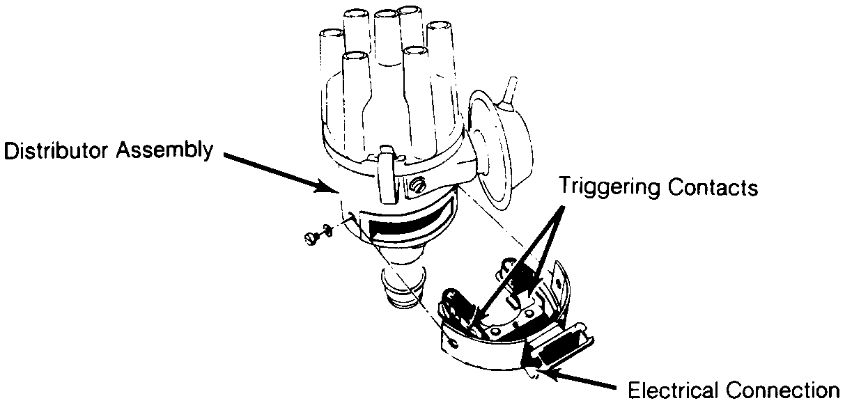 Fig. 3; Triggering Contacts & Distributor Throttle Valve Switch The throttle valve switch is mounted on the throttle housing. This switch signals the control unit of throttle position. During deceleration, above 1500 RPM, throttle switch cuts fuel supply off and below 900 RPM, fuel supply is turned on. 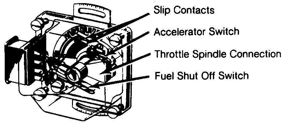 Fig. 4: Throttle Valve Switch Assembly Auxiliary Air Valve During cold starts, the auxiliary air valve opens to allow additional air into the inlet duct. As engine heats up, a bi-metallic element expands and closes valve. At approximately 140°F (80°C) the auxiliary air pipe is completely closed by the valve. 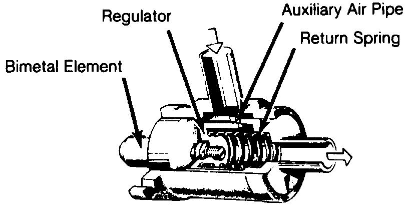 Fig. 5: Auxiliary Air Valve Assembly TROUBLE SHOOTING PRELIMINARY CHECKS Prior to trouble shooting the fuel injection system, check the following items: *Battery condition. *All electrical connections. *Hoses or mating surfaces for vacuum leakage. *Fuel lines for leakage. *Ignition system. *Idle speed and mixture. TROUBLE SHOOTING Engine Will Not Start, Fuel Pump Inoperative Check the following: Defective fuse, fuel pump. fuel pump relay, main relay or electrical circuit. Fuel pump relay should click when ignition is switched on and off. Should have voltage from main relay terminal No. 87 to fuel pump relay terminal No. 86. Fuel pump relay terminal No. 85 should have good ground from ECU. NOTE *Fuel pump operates approximately ½ to 1 second after switching ignition on. Relay is grounded from ECU. Ensure fuel pump operates during cranking. Engine Will Not Start, Fuel Pump Operates Check the following: Defective wire to starter terminal No. 50, Manifold Pressure Control (MPC) sensor and/or wiring, temperature sensors and/or wiring. Inadequate pressure in main fuel system, wire connector for distributor contacts disconnected and/or open circuit. Pressure should be 28 psi (2.0 kg/cm2) with starter operating. Engine Starts, Then Stalls When Cold Check the following: Defective trigger contacts and/or wiring, MPC sensor or temperature sensors. Engine Will Not Start Warm Check the following: Defective thermotime switch, temperature sensors or high resistance at trigger contacts. Engine Stalls And May Misfire Check the following: Excessive resistance at trigger contacts, dirty trigger contacts, loose connector, temperature sensors or inadequate vehicle ground. Engine Runs Rough, White Smoke Comes From Exhaust Check the following: Injector sticking or connection to injector windings faulty. Lack of Power Check the following: Defective MPC sensor, fuel pressure too low, restricted air throttle valve or full-load contact does not close. Excessive Fuel Consumption Check the following: Defective sensors, ECU, MPC, improperly adjusted throttle switch or inadequate fuel pressure. Engine Idles Erratically Between 1000 and 2000 RPM Check the following: Hose between auxiliary air regulator and intake air distributor disconnected or cracked, throttle valve not closed at idle or idle speed too high. High Idle, Unadjustable Check the following: Vacuum leak, injector valve "0" ring leaking or throttle valve out of adjustment. TESTING & DIAGNOSIS NOTE The ECU ground terminal. terminal No. 11, is used for electrical circuit testing. Ensurecontinuity exists between terminal No. 11 of the ECU and the vehicle chassis. VOLTAGE SUPPLY 1) Turn ignition on. Measure voltage between ECU terminals No. 16 and 11 of ECU connector. Measure voltage between ECU terminals No. 24 and 11 of ECU connector. See Fig. 10 or 11. If 11-12.5 volts are present, proceed to step 4). If no voltage is obtained, proceed to next step. If voltage is less than 11 volts, proceed to step 3). 2) If no voltage is present, check for open circuit in wire from main relay to ECU, defective main relay and/or ignition switch. Check for voltage at main relay terminals No. 86, 30/51 and 87. Replace relay as necessary. 3) If voltage is less than 11 volts, check for resistance in wires and/or connectors at ECU and main relay. Repair or replace as necessary. 4) If voltage supply to ECU and main relay is okay, check for voltage between terminal No. 50 on starter and ground. If 9-12 volts are present. system is okay. If no voltage but starter operates. repair open in wire from starter terminal No. 50 to ECU terminal No. 18. if less than 9 volts, check battery and resistance in wire from ignition switch to starter. If no voltage and starter is inoperative, replace ignition switch and/or repair open wire to starter. FUEL PUMP Connect pressure tester in fuel line between fuel pump and fuel supply lines. Remove injectors, fuel supply lines to intake manifold and cold start injector valve. Place pan beneath all injectors, to catch fuel being discharged. Connect remote starter switch to terminal No. 50 on starter and to positive terminal of battery. Run starter and check that all injectors spray properly and evenly. If any one injector does not spray correctly, replace that injector. Remove wire from terminal No. 33 of thermotime switch and ground the removed wire. if cold start injector does not spray, replace it. Operate starter and check fuel pressure. Pressure should be 3.0 psi (.21 kg/cm2). If pressure is below specifications, crimp off fuel return line. Pressure should increase to 64.0 psi (4.5 kg/cm2). If pressure does not increase, or increase is not sufficient, check fuel filter, lines and/or pump. Remove crimp in fuel return line. if pressure is above initial specifications, adjust pressure regulator. If pressure does not decrease when crimped line is released, replace pressure regulator. MANIFOLD PRESSURE CONTROL (MPC) SENSOR Disconnect the harness connector at the MPC. Check the resistance at the MPC terminals. Terminal No. 11 is the ground circuit, there should be infinite resistance (open circuit) between terminal No. 11 and terminals No. 7, 8,10, and 15. Check primary resistance between terminals No. 7 and 15. Resistance should be about 90 ohms. Check secondary resistance between terminals No. 8 and 10. Resistance should be about 350 ohms. If resistance values are not to specifications or a short (continuity) exists between the ground circuit (terminal No. 11) and any of the other terminals, replace the sensor. To check the harness, ensure MPC is disconnected and ignition is off. With the ECU connected ensure continuity exists between terminal No. 11, at the MPC connector, and vehicle chassis. If there is resistance in this circuit or an open exists, check ECU ground circuit. Disconnect the ECU connector. Check wiring continuity between the ECU and MPC connectors. If there is resistance (above 5 ohms) or an open, repair or replace wiring as necessary. With ECU and MPC disconnected there should not be continuity between harness terminals No. 1. 8, 10, or 15 and ground, if there is, repair short in wiring. INJECTORS Connect fuel pressure tester in line between fuel pump and fuel supply lines. Remove injectors and cold start injector valve. Place pan under all injectors, to catch fuel being discharged. Turn on ignition and operate a remote starter switch. Check spray of all injectors. If any one injector does not operate, replace it and recheck. If all Injectors of either group do not spray, check trigger contacts of distributor, trigger contact wiring to ECU and wires from ECU to injectors. If wires and connections check okay, replace ECU and recheck. If defect is still present, replace all injectors in that group and recheck. If recheck still shows defect, try another ECU. If none of the injectors operate, disconnect MPC sensor electrical connector. Connect ohmmeter across terminals No. 15 and 7 of sensor. Reading should be 90 ohms. Connect ohmmeter across terminals No. 8 and 10. Reading should be 350 ohms. Reading between terminal No. 7 and ground should be infinite. If any of these readings are not within specifications, replace MPC sensor. Sticking injectors can be detected with engine running. Connect tachometer, run engine and disconnect electrical connector to one injector at a time. Note RPM decrease. It RPM drop from one cylinder differs from that of all other cylinders, a faulty injector is indicated. Replace that injector and recheck. If same injector still show a defect, replace ECU and recheck. NOTE Do not overlook possibility of restriction in fuel line or connection to that injector. COLD START INJECTOR Perform pressure test. See step 1) under INJECTORS in this article. If cold start injector leaks during test it is defective and must be replaced. Remove connector at thermotime switch. and ground wire. Cold start injector should spray fuel during engine cranking. If fuel does not spray, temperature is either above 95°F (35°C) or injector is defective. AIR & ENGINE TEMPERATURE SENSORS Disconnect electrical connectors of each temperature sensor. Use ohmmeter across terminals of sensor. If engine temperature is 68°F (20°C), air temperature sensor should have resistance of 260-340 ohms and engine temperature sensor should have resistance of 2100-3100 ohms. Each should have infinite resistance between terminals and ground. 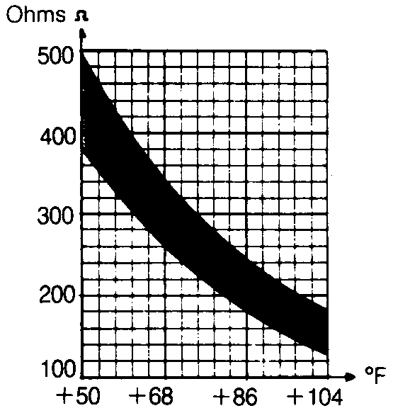 Fig. 6: Air Temperature Sensor Resistance 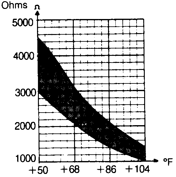 Fig. 7: Engine Temperature Sensor Resistance 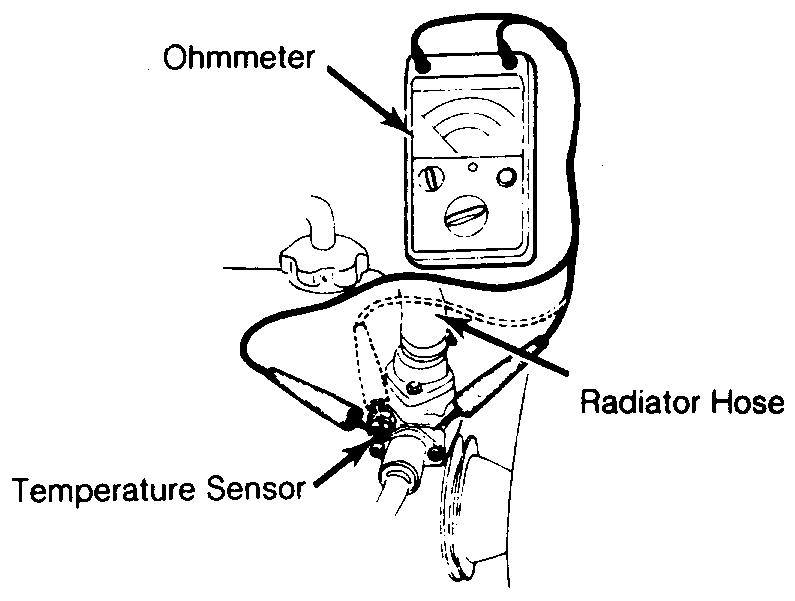 Fig. 8: Test Connections of Engine Temperature Sensor THROTTLE VALVE SWITCH NOTE * If throttle terminal has voltage at all times, replace switch. If switch has no voltage, either before or after adjustment, replace switch. 1) Remove air cleaner. Loosen lock nut on throttle stop screw and turn out screw until it no longer touches throttle boss. Check that throttle is completely closed and throttle bore is clean. Screw in stop screw until It just touches boss, then turn it one additional full turn. Tighten lock nut. 2) Connect ohmmeter to terminals No. 9 and 12 of ECU connector. Depress accelerator slowly. Ohmmeter should fluctuate from zero to infinity. If zero reading only, replace switch. 3) Place accelerator at idle. Connect ohmmeter between terminals No. 12 and 17 of ECU connector. Ohmmeter should show continuity (zero ohm). If infinity reading is achieved, check throttle valve adjustment and/or check for open circuit. If infinity reading is still achieved. replace switch. 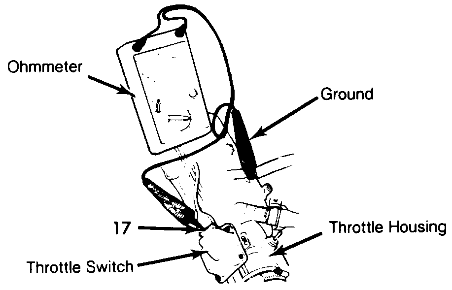 Fig. 9: Test Connections of Throttle Switch 4) Slightly depress accelerator. Connect ohmmeter between terminals No. 12 and 17 of ECU connector. Ohmmeter should show infinity. If continuity (zero ohm) is achieved, check throttle valve adjustment and/or short in wires. Disconnect throttle valve switch and check ohmmeter reading. If continuity (zero ohm) is still achieved, and wires are okay, replace switch. AUXILIARY AIR VALVE Remove hoses connected to each side of air valve. With cold engines (less than 95°F, 39°C), auxiliary air regulator should be at least partially open. To check valve, use a mirror and light and look through valve opening. Turn ignition on and make sure regulator valve closes within a few minutes. DISTRIBUTOR TRIGGER CONTACTS Attach one ohmmeter lead to terminal No. 12 on trigger connector. Alternately attach second lead to terminals No. 13, 14, 21 and 22 on trigger connector and note reading of each, while cranking engine without starting. See Fig. 10 or 11. Ohmmeter should fluctuate between infinity and zero. If ohmmeter reading remains either infinity or zero, check each wire and connector terminal. If wires and terminals check okay, replace trigger contacts. ELECTRONIC CONTROL UNIT Without the use of special test equipment. the only way to check ECU operation is to substitute a known good ECU and test drive vehicle. Substituting a good ECU for a suspected defected ECU should only be done after all other components have been tested and repaired. Installing a good ECU while a problem still exists elsewhere in the system, could result in destroying the good ECU. ADJUSTMENTS PRESSURE REGULATOR Remove hose at pressure regulator and connect pressure gauge to regulator. Operate fuel pump. Pressure should be 28 psi (2.0 kg/cm2). Loosen lock nut on regulator and adjust as necessary. Replace regulator if specifications can not be achieved. THROTTLE VALVE Loosen lock nut on stop screw for throttle valve switch and turn out a couple of turns, so it does not touch stop on throttle valve spindle. Check to ensure switch is fully closed. Screw in stop screw until it touches stop on switch spindle. Turn screw in ¼ - 1 turn and tighten lock nut. Check that throttle valve switch does not jam or seize in closed position. THROTTLE VALVE SWITCH Remove air cleaner and place a .016" (.41 mm) feeler gauge between boss and stop screw. Connect voltmeter to terminal No. 17 on throttle valve switch and ground. Loosen switch retaining screws enough to move switch. Turn switch counterclockwise to its stop. Voltmeter reading should be zero volt. Now turn throttle switch clockwise and tighten retaining screws exactly at point a reading is noted on voltmeter. IDLE ADJUSTMENT With engine at normal operating temperature, attach tachometer and CO meter to engine. Ensure auxiliary air regulator is closed by pulling off hose between intake duct and the regulator and covering the opening. Engine RPM should not change. If RPM changes significantly, engine is either not warm or air regulator is faulty. See IDLE ADJUSTMENT SPECIFICATIONS table in this article. Adjust idle RPM with idle adjustment screw. Reconnect hose from air cleaner. Adjust CO using the adjustment screw on the ECU. Turning the adjusting clockwise increases CO content. IDLE ADJUSTMENT SPECIFICATIONS Model CO% Idle RPM Mercedes-Benz W/3.5L Engine 280 SE & 280 SEL 1.0-2.0 700-850 280 SEC (To Oct. 1970) 1.0-2.0 700-850 280 SEC (From Nov. 1970) 1.5-3.5 700-850 300 SEL 1.5-3.0 700-850 350 SEL 1.5-3.5 700-850 W/4.5L Engine All Models 0.5-2.0 700-800 Porsche 914 1970-71 .7 850-950 1972 .7 850-900 1973 1.7L .7 850-900 2.0L.1.5 1.5 850-950 1974 (1.8L) 2.0-3.0 800-900 1974-75(2.0L) 1.0-3.0 850-950 Saab 99E 2.5-3.5 750-850 Volkswagen Type 3 1968 1969-70 2.8-3.1 1 850-900 1971 1972 .7 2 800-900 1973 2 850-900 Type 4 1971 1972 .7 850-900 1973 850-900 1974 Volvo 1800E, 1800ES, 142 & 144 M/T 1.0-2.0 900 A/T 0.5-1.0 800 164E MIT 1.0-1.5 900 AfT 0.5-1.0 800 1 - With A/T, 1000 2 - With A/T, 900 - 1000. NOTES for Fig. 10: Typical 4-Cyl. Bosch D-Jetronic Fuel Injection Wiring Diagram 1. ECU Connector 2. MPC Sensor 3. Cylinder Head Temp. Sensor 4. Intake Manifold Temp. Sensor 5. Injector 6. Thermotime Switch 7. Cold Start Valve 8. Distributor/Trigger Contacts 9. Engine Speed Relay (1972 models) 10. EGR Switch Unit (Some models) 11. Throttle Valve Switch 12. Vacuum Advance Disconnection 2-Way Valve 13. EGR Valve 14. Air Valve for Auxiliary Air Supply (1972 models) 15. From Starter Terminal No. 50 16. EGR Thermoswitch 17. A/T Oil Pressure Switch (1972 models) 18. Fuel Pump 19. Auxiliary Air Valve (If Equipped) 20. To Fuse Box Terminal No. 30 21. Fuel Pump Relay 22. To Battery 23. Main Relay 24. To Ignition Switch Terminal No. 15 or Ignition Coil Terminal No. 15 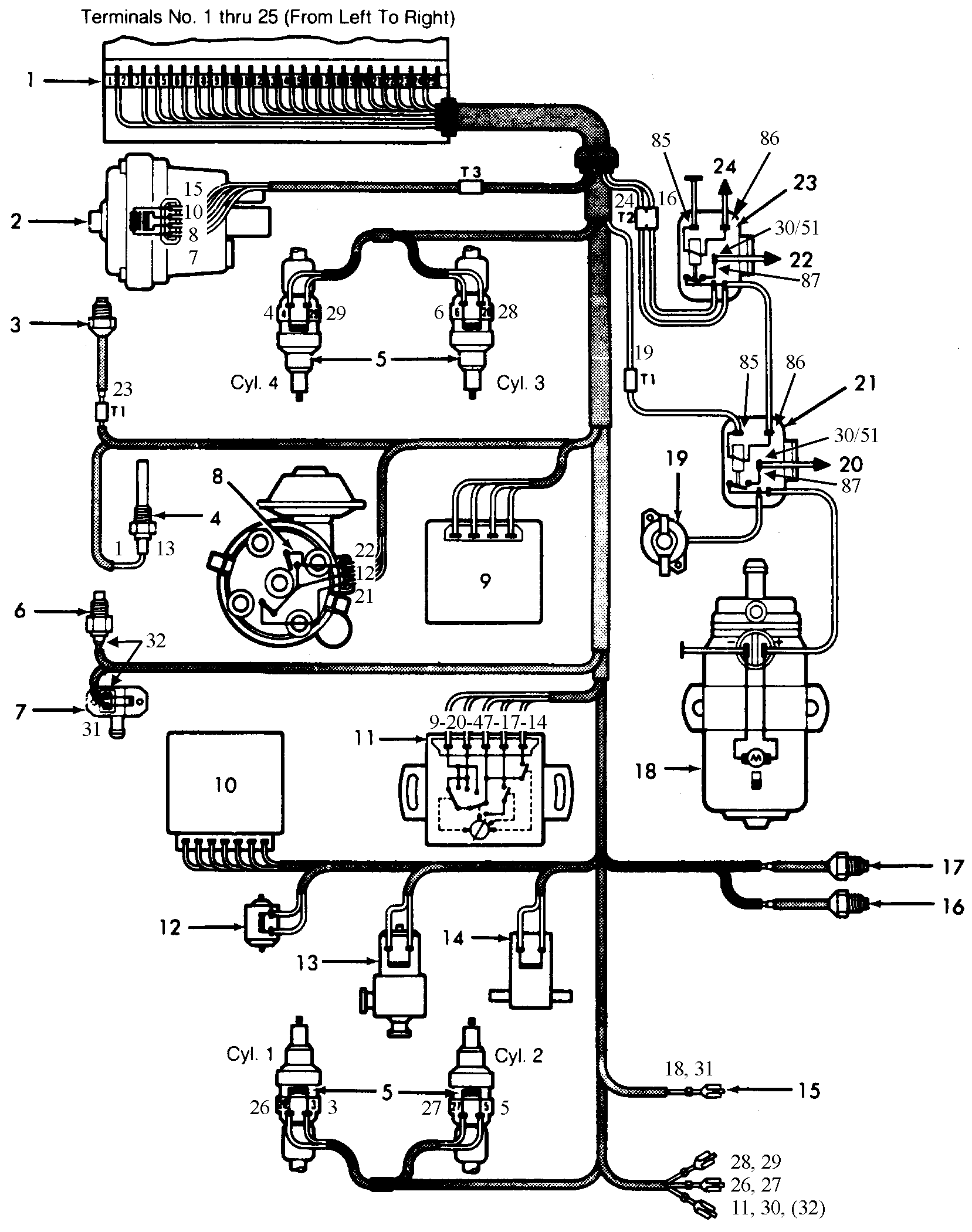 Fig. 10: Typical 4-Cyl. Bosch D-Jetronic Fuel Injection Wiring Diagram (See notes on previous page) |
| type47 |
 May 1 2006, 05:23 AM May 1 2006, 05:23 AM
Post
#2
|
|
Viermeister     Group: Members Posts: 4,254 Joined: 7-August 03 From: Vienna, VA Member No.: 994 Region Association: MidAtlantic Region |
good info, thanks. what is the source of this and is there a link?
|
| Air_Cooled_Nut |
 May 1 2006, 07:04 PM May 1 2006, 07:04 PM
Post
#3
|
|
914 Ronin - 914 owner who lost his 914club.com    Group: Members Posts: 1,748 Joined: 19-April 03 From: Beaverton, Oregon Member No.: 584 Region Association: None |
|
| cassidy_bolger |
 May 1 2006, 09:56 PM May 1 2006, 09:56 PM
Post
#4
|
|
Member   Group: Members Posts: 106 Joined: 17-March 06 From: = Member No.: 5,737 Region Association: None |
Perfect, just got my car and don't know the front from the back yet. When I find the engine, this might come in handy.
Thanks (IMG:style_emoticons/default/blink.gif) |
| roadwarriors |
 Feb 14 2022, 10:17 PM Feb 14 2022, 10:17 PM
Post
#5
|
|
Newbie  Group: Members Posts: 2 Joined: 14-February 22 From: usa Member No.: 26,337 Region Association: Pacific Northwest |
great info thank u
|
  |
1 User(s) are reading this topic (1 Guests and 0 Anonymous Users)
0 Members:

|
Lo-Fi Version | Time is now: 2nd April 2025 - 05:54 PM |
Invision Power Board
v9.1.4 © 2025 IPS, Inc.


