|
|
|
Porsche, and the Porsche crest are registered trademarks of Dr. Ing. h.c. F. Porsche AG.
This site is not affiliated with Porsche in any way. Its only purpose is to provide an online forum for car enthusiasts. All other trademarks are property of their respective owners. |
|
|

  |

| MrKona |
 Jun 1 2008, 02:06 AM Jun 1 2008, 02:06 AM
Post
#61
|
|
Senior Member  Group: Members Posts: 597 Joined: 25-July 05 From: Santa Rosa, CA Member No.: 4,469 Region Association: None |
Next up was the installation of the cylinder heads, making damn sure that the head with the cylinder head temp sensor threaded hole is on the passenger side...
I torqued the heads in a criss-cross pattern, as illustrated on page 135 of Tom Wilson's book. I also followed his advice for the torquing of both heads: 1. Head one to 15 ft/lb, then head two to 15 ft/lb. 2. Head one to 20 ft/lb, then head two to 23 ft/lb. 3. Head one to 23 ft/lb, retorque head two to 23 ft/lb. 4. Wait a couple minutes retorque both heads to 23 ft/lb. The next thing to go on after the heads are the under-cylinder tins. These need to go on before the pushrod tubes. I had these chemically cleaned at the metal cleaner when I had my case done. They came back nice and clean, but a little rough. I primed and painted them. I'm sure it will all burn off the first time I drive the car, but at least it looks nice during assembly... If I had been planning this better, I would have had them professionally coated and waiting for installation. I kept a paper towel tucked under the cylinder tin as I installed the fasteners. Last thing I wanted was to drop one and have it fall into the case. Attached thumbnail(s) 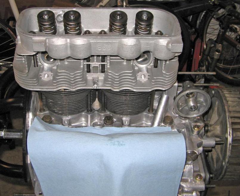 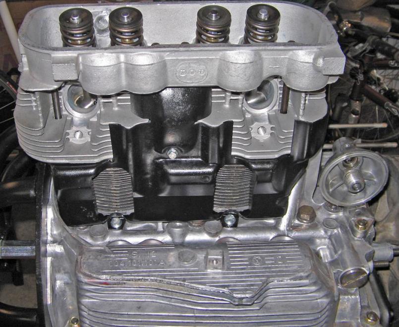
|
   |

 
|
| MrKona |
Jun 1 2008, 02:12 AM
Post
#62
|
|
Senior Member Group: Members Posts: 597 Joined: 25-July 05 From: Santa Rosa, CA Member No.: 4,469 Region Association: None |
Next was the pushrod tube installation. As everyone advocates, I used clean motor oil and nothing else on the pushrod seals. They went in fairly easily. There's no way I could install the tubes with my hands in the cramped space, so I carefully used large pliers. I cut apart a vacuum cleaner rubber belt and placed a piece of it under the plier's jaws so as not to damage the tube, and also to get a better grip on the tube. Just make sure the outer tube is clean, so you don't have to squeeze too tightly to get a good grip. Twist and push, and they sank right into their recess. I made sure to put a couple drops of oil in the case recesses to prevent damaging a seal.
Attached thumbnail(s) 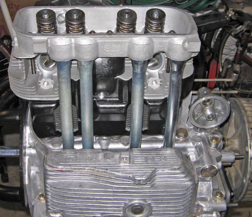 Attached image(s) 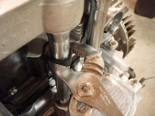
|
|
|
|
| MrKona |
Jun 1 2008, 02:16 AM
Post
#63
|
|
Senior Member Group: Members Posts: 597 Joined: 25-July 05 From: Santa Rosa, CA Member No.: 4,469 Region Association: None |
And that's all for tonight!
Attached thumbnail(s) 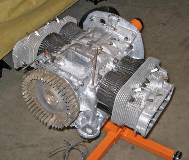 Attached image(s) 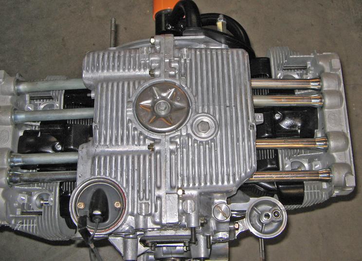
|
|
|
|
| SGB |
Jun 1 2008, 10:37 PM
Post
#64
|
|
just visiting Group: Members Posts: 4,086 Joined: 8-March 03 From: Huntsville, AL Member No.: 404 Region Association: South East States |
looks great!
|
|
|
|
| MrKona |
Aug 4 2008, 02:03 AM
Post
#65
|
|
Senior Member Group: Members Posts: 597 Joined: 25-July 05 From: Santa Rosa, CA Member No.: 4,469 Region Association: None |
It's been awhile since I posted any progress. By no means have I lost interest in this project. Just some delays due to competing priorities... sound familiar? The engine has been sitting under plastic in the garage, waiting for me to work on it again. I set up the valvetrain geometry this weekend. I've read Jakes article many times, and searched on this site for some great information. I used an adjustable pushrod to calculate all the pushrod lengths for each valve, and have cut four. I started getting a little fatigued earlier tonight so I figured it was time to call it a night.
A couple details: Solid spacers and swivel head adjusters. I sanded down some of the adjusters with very fine sand paper as some of the rockers fit pretty tight when first mocked the assemblies on the case. I've got them so they rock smoothly with no side to side play. Steel pushrods. I cut them with a small pipe cutter and finished off with a grinder, deburred with a small file. Blew them clean with carb cleaner and compressed air. I had two old lifters that I used to hold the ends while I tapped in the pushrod tip. My set up, as you can see is just a steel plate (the piece I used as a crank holder earlier in the build). Worked great to mount the magnetic dial indicator stand. All measurements at full lift are within +/- 5% lift specs for the 9550 cam. At half lift, the valves and adjusters are about as straight as I can possibly see: Assemble, measure, disassemble, adjust, reassemble, repeat... Lot's of fun! Here's a couple random pictures from the process: Attached thumbnail(s) 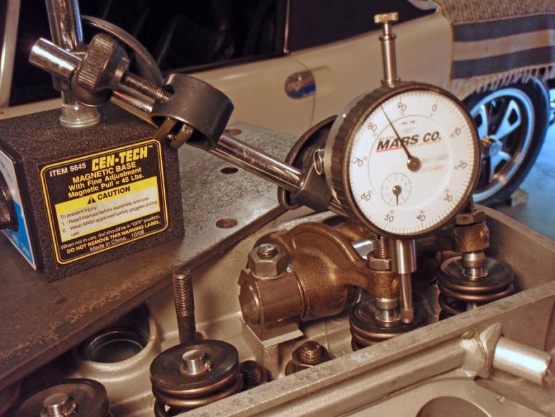 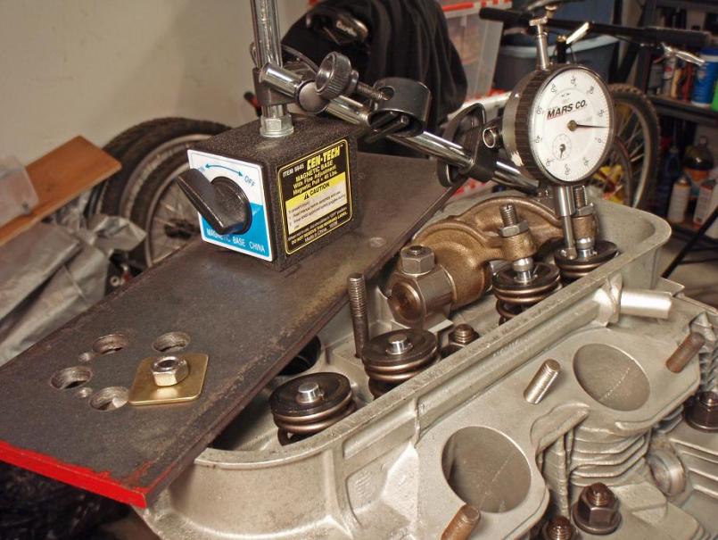 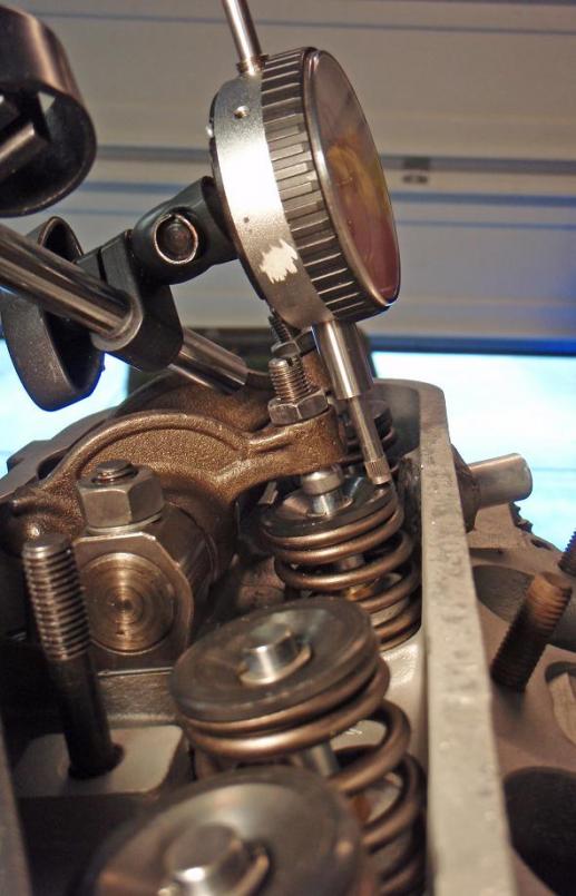
|
|
|
|
| MrKona |
Aug 4 2008, 02:05 AM
Post
#66
|
|
Senior Member Group: Members Posts: 597 Joined: 25-July 05 From: Santa Rosa, CA Member No.: 4,469 Region Association: None |
More...
Attached thumbnail(s) 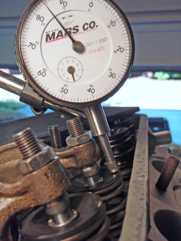 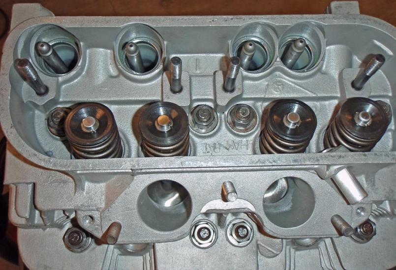 Attached image(s) 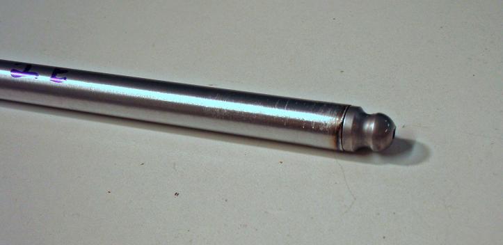
|
|
|
|
| MrKona |
Aug 4 2008, 02:06 AM
Post
#67
|
|
Senior Member Group: Members Posts: 597 Joined: 25-July 05 From: Santa Rosa, CA Member No.: 4,469 Region Association: None |
Last ones.
Attached thumbnail(s) 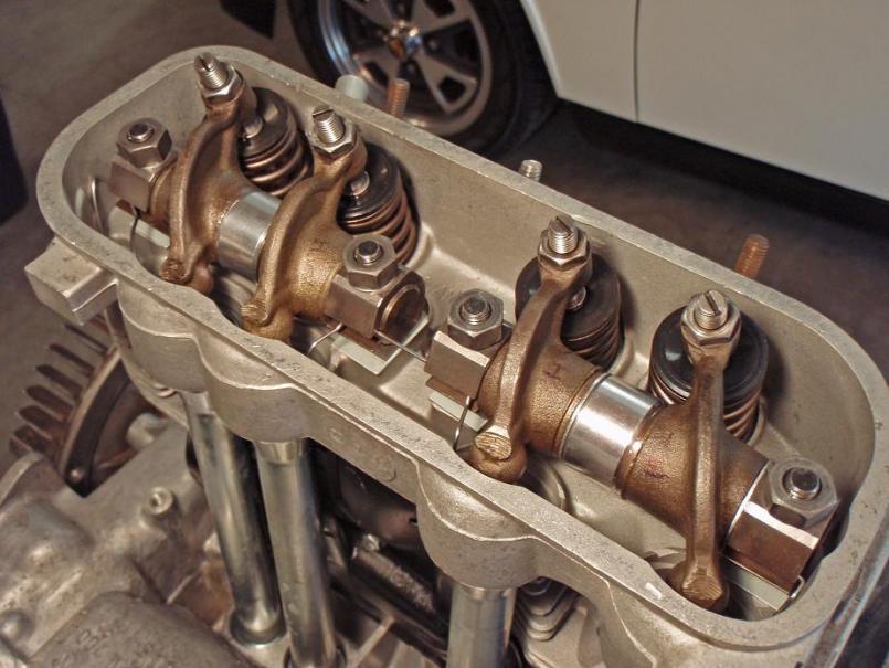 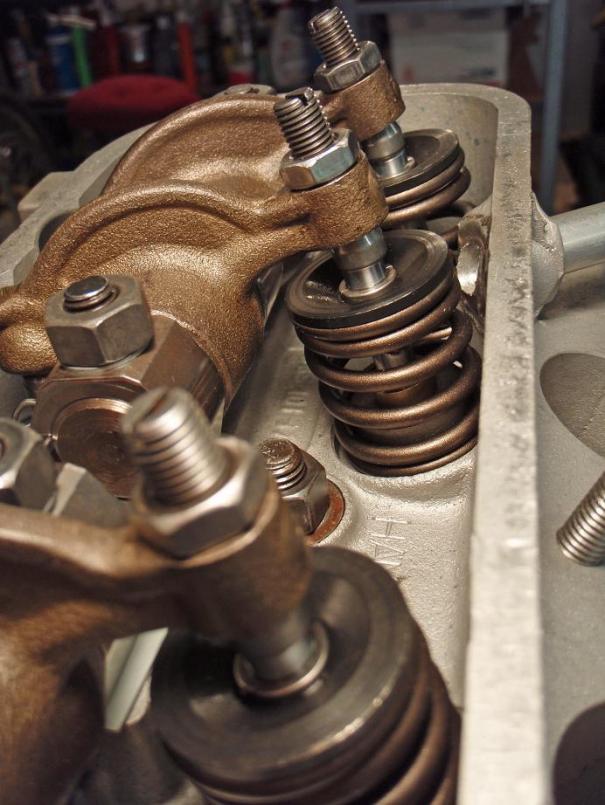
|
|
|
|
| MrKona |
Aug 6 2008, 08:34 PM
Post
#68
|
|
Senior Member Group: Members Posts: 597 Joined: 25-July 05 From: Santa Rosa, CA Member No.: 4,469 Region Association: None |
Valves installed and adjusted. I've come as far as I can without dropping the current engine and transferring some parts. The next few weeks will undoubtedly be spent working out some rich running fuel injection issues with the current engine. I want to get all that sorted out before installing the new engine. I'm going to have the tins and runners powder coated to look factory fresh. I also picked up some new engine compartment rubbers seals from Mark at 914rubber.com. Thanks Mark.
I have a question regarding the 1.8 fan and distributor I'll be taking off my 1.8 engine. The fan that came with this engine has a broken fin. I was originally thinking that I would find another 2.0 fan to replace it. But thinking about it more, should I actually keep the 1.8 fan and distributor from the current engine together, rather than mixing a 2.0 fan and a 1.8 distributor? I believe the timing marks are different on the 1.8 fans (timing mark at 7.5 degrees BTDC on the 1.8 fan). Do the marks on the 1.8 fan specifically correlate to the notch on the 1.8 distributor? Attached thumbnail(s) 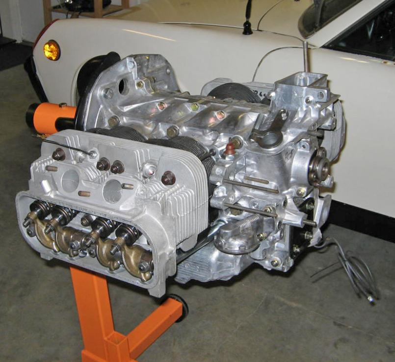
|
|
|
|
| Rav914 |
Aug 6 2008, 09:38 PM
Post
#69
|
|
All-weather fan Group: Members Posts: 738 Joined: 15-April 07 From: WA Member No.: 7,669 Region Association: None |
Great thread. I've been following closely as I'm rebuilding my 1.7 into a 1.9. Will try to emulate your cleanliness.
Sorry, I don't know the answer to your fan question. |
|
|
|
| MrKona |
Feb 7 2009, 01:27 AM
Post
#70
|
|
Senior Member Group: Members Posts: 597 Joined: 25-July 05 From: Santa Rosa, CA Member No.: 4,469 Region Association: None |
Gotta keep this thread alive... Just a tiny bit of progress tonight. New rubber engine mounts, and freshly blasted and repainted case mounts. Also new mount to case bolts. I like looking at the before and after photos.
Attached thumbnail(s) 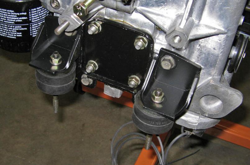 Attached image(s) 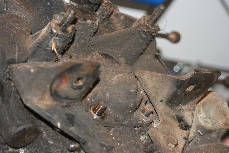
|
|
|
|
| MrKona |
Feb 7 2009, 01:33 AM
Post
#71
|
|
Senior Member Group: Members Posts: 597 Joined: 25-July 05 From: Santa Rosa, CA Member No.: 4,469 Region Association: None |
Also blasted and painted the thermostat mount and reinstalled the thermostat. Since I built my blast cabinet, I find myself looking around my garage for things to blast clean.
I had repaired this thermostat awhile back by injecting 99% alcohol and brazing a leak on the top. It's now back in spec for expansion and temp. Attached thumbnail(s) 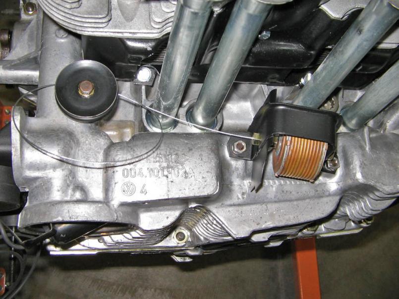
|
|
|
|
| type47 |
Feb 7 2009, 06:33 AM
Post
#72
|
|
Viermeister Group: Members Posts: 4,254 Joined: 7-August 03 From: Vienna, VA Member No.: 994 Region Association: MidAtlantic Region |
i enjoy reading your thread of the build up and as i read it, went back to my own engine build up. you put in the pushrod tubes but didn't mention (or i read too fast) that you put in the lifters so i "hey, what about the lifters!" to myself of course you had to install them before the valve train geometry steps. your thread is a great inspiration and a great example of how things should be done. you could turn this into a "how to" DVD! keep us posted.
|
|
|
|
| MrKona |
Feb 7 2009, 06:27 PM
Post
#73
|
|
Senior Member Group: Members Posts: 597 Joined: 25-July 05 From: Santa Rosa, CA Member No.: 4,469 Region Association: None |
QUOTE(type47 @ Feb 7 2009, 04:33 AM)  i enjoy reading your thread of the build up and as i read it, went back to my own engine build up. you put in the pushrod tubes but didn't mention (or i read too fast) that you put in the lifters so i "hey, what about the lifters!" to myself of course you had to install them before the valve train geometry steps. your thread is a great inspiration and a great example of how things should be done. you could turn this into a "how to" DVD! keep us posted. Good point! Yes, you must install the lifters before you install the push rod tubes. The lifters won't fit through the tubes. I'm glad you're enjoying the thread, I take that as a compliment. |
|
|
|
| FourBlades |
Feb 7 2009, 10:12 PM
Post
#74
|
|
From Wreck to Rockin Group: Members Posts: 2,055 Joined: 3-December 07 From: Brevard, FL Member No.: 8,414 Region Association: South East States |
Wow, your engine looks great. Your photos are so clear and focused. So much better than most books that are supposed to teach you about engines. I almost think Hanes found the grungiest possible car and then took the worst possible pictures. How are you lighting the photos? Are you using any flash? Can you show how to set the valve clearance? John |
|
|
|
| MrKona |
Dec 27 2009, 08:01 PM
Post
#75
|
|
Senior Member Group: Members Posts: 597 Joined: 25-July 05 From: Santa Rosa, CA Member No.: 4,469 Region Association: None |
The engine is off the stand and tin and FI components are being added. I had the top tins powder coated. All the rest I painted with high temp paint.
Front side tins went on first. Attached thumbnail(s) 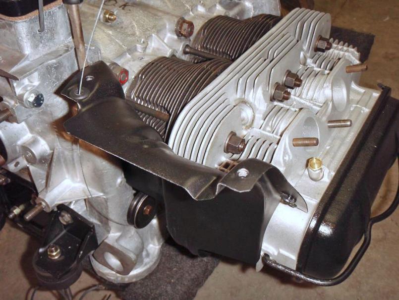 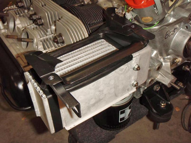
|
|
|
|
| MrKona |
Dec 27 2009, 08:03 PM
Post
#76
|
|
Senior Member Group: Members Posts: 597 Joined: 25-July 05 From: Santa Rosa, CA Member No.: 4,469 Region Association: None |
Then the fan shroud and fan.
You may want to temporarily tape the front passenger tin in place. There's nothing holding it in place until the top tins go on. It fell off after I put the shroud on. It found its way off, but I couldn't get it back into place without removing the shroud. Attached thumbnail(s) 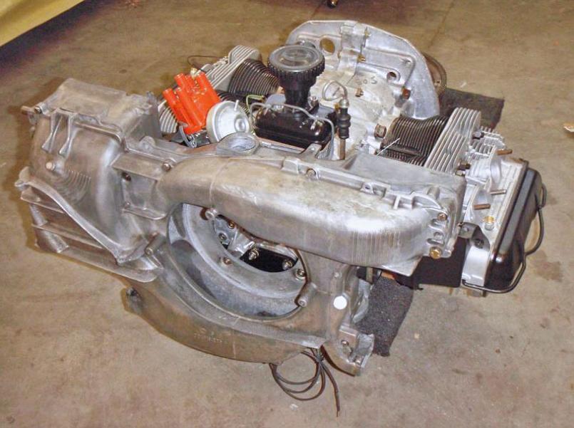 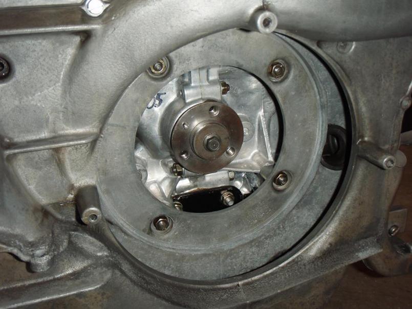 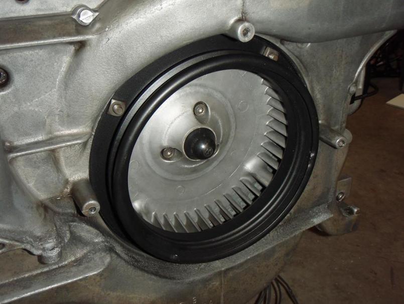
|
|
|
|
| MrKona |
Dec 27 2009, 08:11 PM
Post
#77
|
|
Senior Member Group: Members Posts: 597 Joined: 25-July 05 From: Santa Rosa, CA Member No.: 4,469 Region Association: None |
Then I attached the cooling flaps and thermostat cable. By the way, Ace Hardware has a really good selection of rubber grommets. I found one for the thermostat cable hole that fit great.
Attached thumbnail(s) 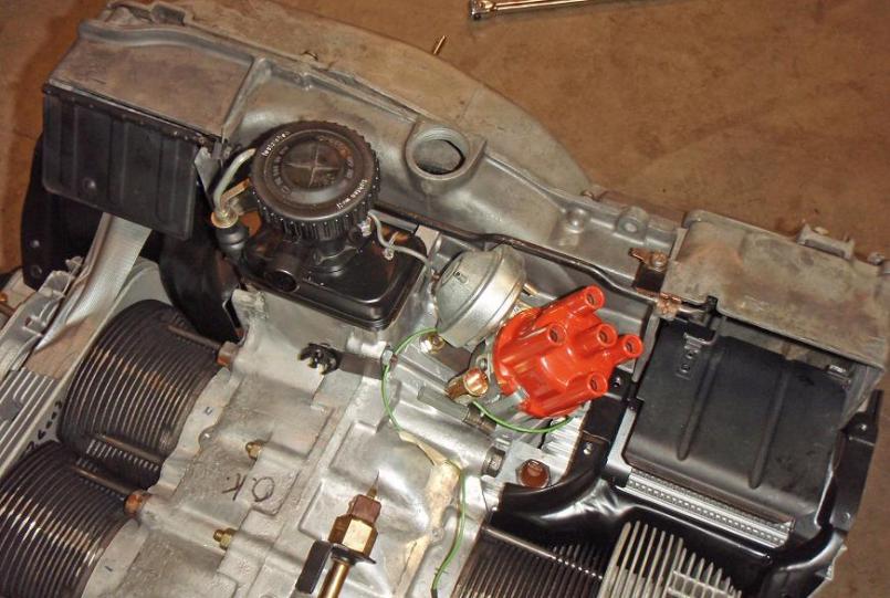 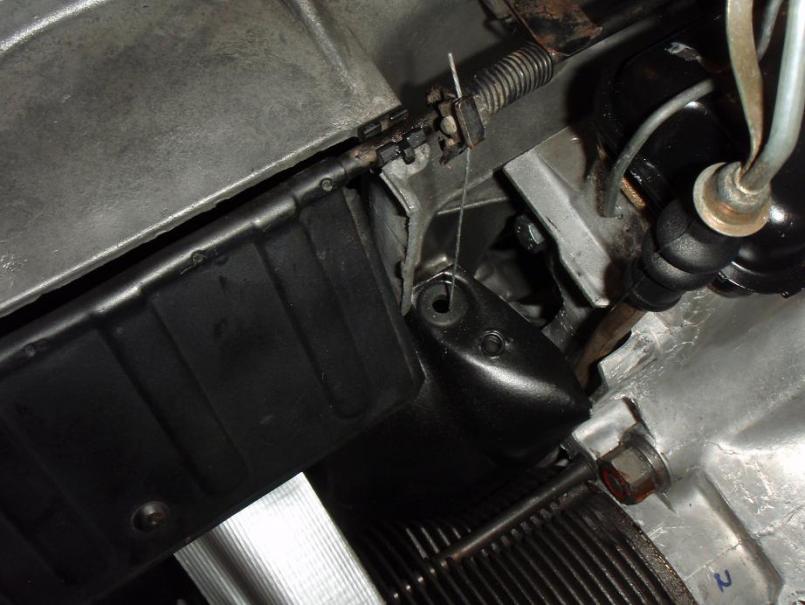
|
|
|
|
| MrKona |
Dec 27 2009, 08:16 PM
Post
#78
|
|
Senior Member Group: Members Posts: 597 Joined: 25-July 05 From: Santa Rosa, CA Member No.: 4,469 Region Association: None |
And then the top tins! I had to remove the distributor to place the right side tin.
Also started adding some FI components. My plan is to use the original L-jet components, just adding a set of 2.0 intake tubes which are drilled for the 3-stud cylinder heads... Attached thumbnail(s) 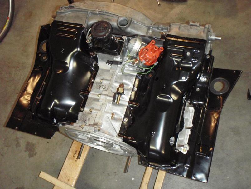 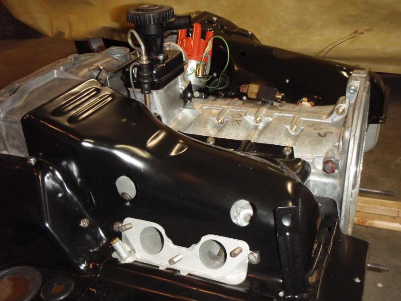 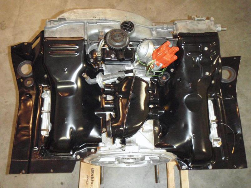
|
|
|
|
| MrKona |
Dec 27 2009, 08:19 PM
Post
#79
|
|
Senior Member Group: Members Posts: 597 Joined: 25-July 05 From: Santa Rosa, CA Member No.: 4,469 Region Association: None |
And this is where my momentum stopped... I acquired a set of 2.0 3-stud intake tubes. Had them cleaned, then I painted them in gray similar to the factory tubes to make them all pretty...
Attached thumbnail(s) 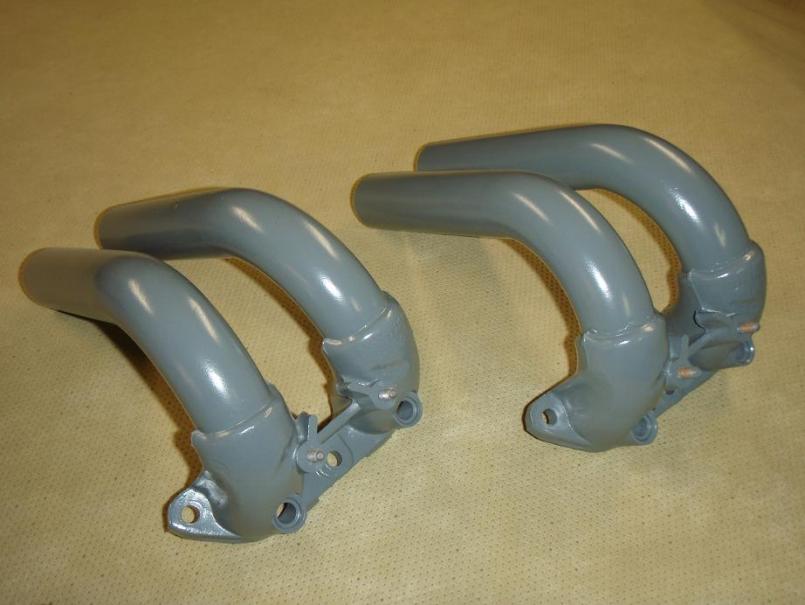
|
|
|
|
| MrKona |
Dec 27 2009, 08:23 PM
Post
#80
|
|
Senior Member Group: Members Posts: 597 Joined: 25-July 05 From: Santa Rosa, CA Member No.: 4,469 Region Association: None |
But they don't fit the intake housing! (IMG:style_emoticons/default/mad.gif)
Oh well, looks like I have to clean and paint my existing tubes, and drill an additional hole. I was hoping to make this look really clean with factory 3-stud tubes. That's it for now.. Oh yeah, one more shot - rear tins installed... Attached thumbnail(s) 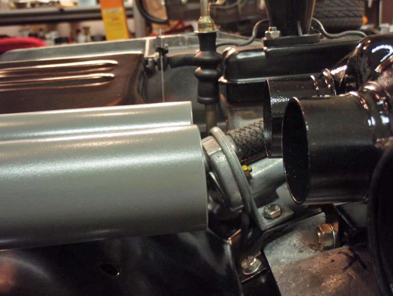 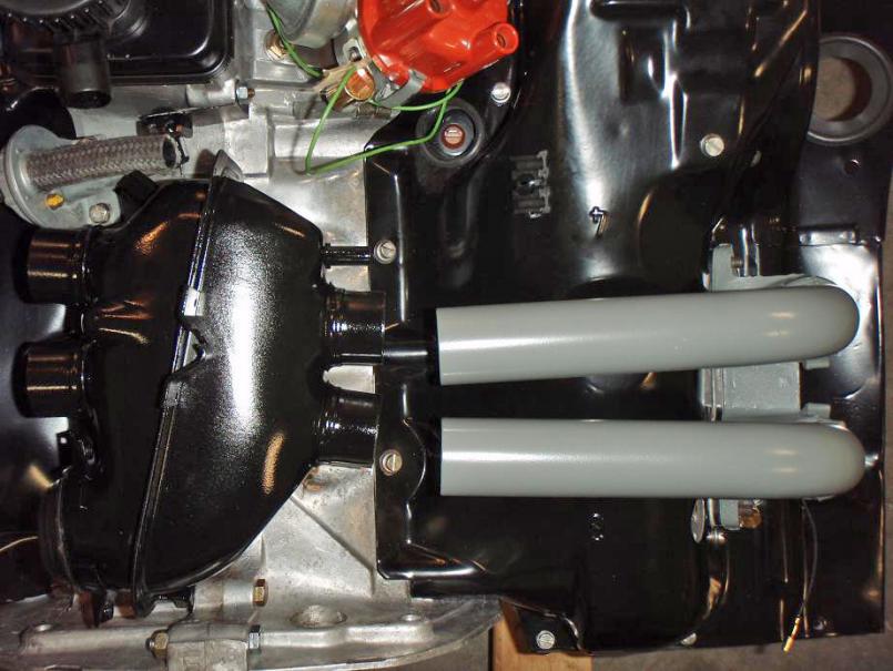 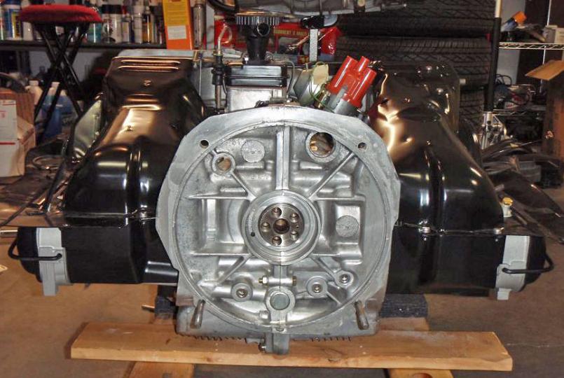
|
|
|
|
|
2 User(s) are reading this topic (2 Guests and 0 Anonymous Users)
0 Members:

|
Lo-Fi Version | Time is now: 3rd July 2024 - 06:19 AM |
Invision Power Board
v9.1.4 © 2024 IPS, Inc.