|
|
|
Porsche, and the Porsche crest are registered trademarks of Dr. Ing. h.c. F. Porsche AG.
This site is not affiliated with Porsche in any way. Its only purpose is to provide an online forum for car enthusiasts. All other trademarks are property of their respective owners. |
|
|

  |

| MrKona |
 Dec 27 2009, 08:29 PM Dec 27 2009, 08:29 PM
Post
#81
|
|
Senior Member  Group: Members Posts: 597 Joined: 25-July 05 From: Santa Rosa, CA Member No.: 4,469 Region Association: None |
QUOTE(FourBlades @ Feb 7 2009, 08:12 PM)  Wow, your engine looks great. Your photos are so clear and focused. So much better than most books that are supposed to teach you about engines. I almost think Hanes found the grungiest possible car and then took the worst possible pictures. How are you lighting the photos? Are you using any flash? Can you show how to set the valve clearance? John Hi John, sorry for the long delayed response. I took the close up pictures with an old Nikon Digital, which I unfortunately no longer own. Light was usually from the camera flash, but some of the close-ups, I just used a shop light and turned the flash off. The flash just drowned out everything in glare. I rested the camera steady on the engine and held the camera as still as possible. As far as setting the valves, I used the standard method with a feeler gauge. By the way, I've really enjoyed your restoration thread! - Bryan |
   |

 
|
| enikolayev |
Jan 30 2010, 08:40 PM
Post
#82
|
|
Member Group: Members Posts: 50 Joined: 18-November 07 From: Gulfport, MS Member No.: 8,349 Region Association: South East States |
Regarding the oil galley plugs, before you tap the holes for 3/8" NPT, it makes the job far easier and cleaner if you drill out the holes with a 37/64" drill bit.
Just an FYI for anyone attempting this. I screwed a few threads when i tried it without drilling. The drill bit saved my case. Hope it helps. |
|
|
|
| Cevan |
Feb 26 2010, 01:35 PM
Post
#83
|
|
Senior Member Group: Members Posts: 1,079 Joined: 11-December 06 From: Western Massachusetts Member No.: 7,351 |
QUOTE(MrKona @ Dec 27 2009, 09:23 PM) But they don't fit the intake housing! (IMG:style_emoticons/default/mad.gif) Oh well, looks like I have to clean and paint my existing tubes, and drill an additional hole. I was hoping to make this look really clean with factory 3-stud tubes. That's it for now.. Oh yeah, one more shot - rear tins installed... Those look like 2 liter intake runners for D-Jet FI. They won't work with an L-Jet plenum. |
|
|
|
| TJB/914 |
Feb 26 2010, 01:51 PM
Post
#84
|
|
Mid-Engn. Group: Members Posts: 4,341 Joined: 24-February 03 From: Plymouth & Petoskey, MI Member No.: 346 Region Association: Upper MidWest |
QUOTE(Cevan @ Feb 26 2010, 11:35 AM) QUOTE(MrKona @ Dec 27 2009, 09:23 PM) But they don't fit the intake housing! (IMG:style_emoticons/default/mad.gif) Oh well, looks like I have to clean and paint my existing tubes, and drill an additional hole. I was hoping to make this look really clean with factory 3-stud tubes. That's it for now.. Oh yeah, one more shot - rear tins installed... Those look like 2 liter intake runners for D-Jet FI. They won't work with an L-Jet plenum. (IMG:style_emoticons/default/agree.gif) You need a 2.0 liter D-Jet plenum. I think I have a mint (powder coated) one off a 73. I'll look for it if your interested. Tom |
|
|
|
| TJB/914 |
Feb 26 2010, 03:10 PM
Post
#85
|
|
Mid-Engn. Group: Members Posts: 4,341 Joined: 24-February 03 From: Plymouth & Petoskey, MI Member No.: 346 Region Association: Upper MidWest |
QUOTE(Thomas J Bliznik @ Feb 26 2010, 11:51 AM) QUOTE(Cevan @ Feb 26 2010, 11:35 AM) QUOTE(MrKona @ Dec 27 2009, 09:23 PM) But they don't fit the intake housing! (IMG:style_emoticons/default/mad.gif) Oh well, looks like I have to clean and paint my existing tubes, and drill an additional hole. I was hoping to make this look really clean with factory 3-stud tubes. That's it for now.. Oh yeah, one more shot - rear tins installed... Those look like 2 liter intake runners for D-Jet FI. They won't work with an L-Jet plenum. (IMG:style_emoticons/default/agree.gif) You need a 2.0 liter D-Jet plenum. I think I have a mint (powder coated) one off a 73. I'll look for it if your interested. Tom MrKona, This is the 2.0 liter air plenum you need. Here's a photo. Tom Attached image(s) 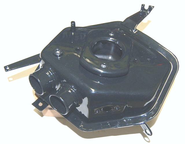
|
|
|
|
| bobhasissues |
Feb 26 2010, 08:48 PM
Post
#86
|
|
seemingly endless issues with my 914 Group: Members Posts: 218 Joined: 13-February 07 From: Chicagoland Member No.: 7,532 Region Association: None |
[quote name='MrKona' date='Dec 27 2009, 08:29 PM' post='1255735']
Can you show how to set the valve clearance? [/quote] As far as setting the valves, I used the standard method with a feeler gauge. [/quote] Double check Jake's instructions regarding the valve clearance when using his chromolly pushrods, I believe they are supposed to have zero lash. Snugged up so the pushrods can be turned, but no lash. Hope this helps. |
|
|
|
| MrKona |
Mar 22 2010, 02:44 PM
Post
#87
|
|
Senior Member Group: Members Posts: 597 Joined: 25-July 05 From: Santa Rosa, CA Member No.: 4,469 Region Association: None |
I'm back after having worked on "project intake runner conversion."
When we last left off, I had realized that my 2.0 3-hole intake runners would not fit my L-jet plenum. Since the D-jet plenum appears to require the 2.0 D-jet air filter and related pieces, I decided to drill my 4-hole L-jet intake runners to 3 holes. Easy enough, except after further inspection, I realized that it was not this simple, as there is a size mismatch between the base of the two runners where they meet up with the cylinder head. Demonstrated here by comparing the gaskets: (IMG:http://www.914world.com/bbs2/uploads_offsite/rosalindapetrisko.smugmug.com-4469-1269290673.1.jpg) I could simply drill the holes, but cosmetically, this wasn't okay. This is where J-B Weld comes in. Using the 3-hole gaskets as templates, I created a mold to mimic the look of a 3-hole intake. (IMG:http://www.914world.com/bbs2/uploads_offsite/rosalindapetrisko.smugmug.com-4469-1269290673.2.jpg) (IMG:http://www.914world.com/bbs2/uploads_offsite/rosalindapetrisko.smugmug.com-4469-1269290673.3.jpg) (IMG:http://www.914world.com/bbs2/uploads_offsite/rosalindapetrisko.smugmug.com-4469-1269290673.4.jpg) First, I filled in the existing holes: (IMG:http://www.914world.com/bbs2/uploads_offsite/rosalindapetrisko.smugmug.com-4469-1269290673.5.jpg) And then the rest: (IMG:http://www.914world.com/bbs2/uploads_offsite/rosalindapetrisko.smugmug.com-4469-1269290673.6.jpg) Removed from the mold: (IMG:http://www.914world.com/bbs2/uploads_offsite/rosalindapetrisko.smugmug.com-4469-1269290673.7.jpg) And sanded smooth: (IMG:http://www.914world.com/bbs2/uploads_offsite/rosalindapetrisko.smugmug.com-4469-1269290673.8.jpg) I then drilled the new holes: (IMG:http://www.914world.com/bbs2/uploads_offsite/rosalindapetrisko.smugmug.com-4469-1269290674.9.jpg) What is not shown here is that I eventually used a template as a "drill bit guide." I drilled the 3-hole stud pattern onto a 1/4" steel plate. It was necessary to use the 1/4" steel plate to guide the drill bit. Even with a drill press and the runner clamped onto the table, the drill press bit wanted to drift to the softer material, in this case, J-B Weld, where the hole being drilled was half on J-B Weld and half on steel. It was the most difficult part of this project. After paint, the final result: (IMG:http://www.914world.com/bbs2/uploads_offsite/rosalindapetrisko.smugmug.com-4469-1269290674.10.jpg) and installed: (IMG:http://www.914world.com/bbs2/uploads_offsite/rosalindapetrisko.smugmug.com-4469-1269290674.11.jpg) (IMG:http://www.914world.com/bbs2/uploads_offsite/rosalindapetrisko.smugmug.com-4469-1269290674.12.jpg) A couple more notes: 1. J-B Weld is rated up to a constant 500 degrees F, so hopefully, it will be okay for this application. 2. I thin the J-B Weld with a little acetone to make it pour easier into the mold. 3. Other Things: This project took awhile because I got side tracked doing a complete restoration on the drill press I was using.. Circle 1950s Atlas, made in Kalamazoo, MI. Great tool, It'll far outlast me. "Before" (IMG:http://www.914world.com/bbs2/uploads_offsite/rosalindapetrisko.smugmug.com-4469-1269290674.13.jpg) "After" (IMG:http://www.914world.com/bbs2/uploads_offsite/rosalindapetrisko.smugmug.com-4469-1269291435.1.jpg) Even recreated the decal. CW for drill presses: (IMG:style_emoticons/default/biggrin.gif) (IMG:http://www.914world.com/bbs2/uploads_offsite/rosalindapetrisko.smugmug.com-4469-1269290674.15.jpg) |
|
|
|
| MrKona |
Mar 22 2010, 02:54 PM
Post
#88
|
|
Senior Member Group: Members Posts: 597 Joined: 25-July 05 From: Santa Rosa, CA Member No.: 4,469 Region Association: None |
And one more of both runners installed..
(IMG:http://www.914world.com/bbs2/uploads_offsite/rosalindapetrisko.smugmug.com-4469-1269291274.1.jpg) The beauty of this project is that it allowed me to use 2.0 three stud cylinder heads and an L-jet plenum, while maintaining a stock look between the intake runners and plenum. No need for non-stock radiator hoses to bridge the gap. |
|
|
|
| MrKona |
Apr 18 2010, 10:28 PM
Post
#89
|
|
Senior Member Group: Members Posts: 597 Joined: 25-July 05 From: Santa Rosa, CA Member No.: 4,469 Region Association: None |
An update of the latest status of my engine rebuild/restoration. I reinstalled the tranny last weekend, and this weekend, I reinstalled the J pipes, flapper boxes, and "Y" pipes (for lack of a better name). I had previously had the J and Y pipes chemically de-rusted. They came back nice clean metal, ready for priming and painting. I used VHT primer and flat gray paint. I think this is pretty close to the original finish. Close enough for me.
Here's a couple shots of the exhaust pieces installed. Notice the Porsche flapper boxes with the stickers still on. I bought these a few years ago from a member here and am finally getting to installed them. Left side: (IMG:http://www.914world.com/bbs2/uploads_offsite/rosalindapetrisko.smugmug.com-4469-1271651283.1.jpg) Right side: (IMG:http://www.914world.com/bbs2/uploads_offsite/rosalindapetrisko.smugmug.com-4469-1271651283.2.jpg) A couple details in this process that I'll point out are the small flaps between the engine shroud and the Y pipes. These originally came with adhesive foam, which mostly disintegrated on my pieces, so I stuck some thin weather stripping to them. Thicker than I would like, but it did the trick and was available at Ace. (IMG:style_emoticons/default/biggrin.gif) (IMG:http://www.914world.com/bbs2/uploads_offsite/rosalindapetrisko.smugmug.com-4469-1271651283.3.jpg) Over these flaps sit the small cover pieces. These pieces originally came with gaskets, which are long gone. I cut a primitive gasket from cork. (IMG:http://www.914world.com/bbs2/uploads_offsite/rosalindapetrisko.smugmug.com-4469-1271651283.4.jpg) It installed easily, and looks like it will seal nicely. (IMG:http://www.914world.com/bbs2/uploads_offsite/rosalindapetrisko.smugmug.com-4469-1271651284.5.jpg) Almost time put the engine back in and free up some garage floor space. I have an old original muffler that I plan on stripping and repainting in gray high temp paint to replace the Sebring. (IMG:http://www.914world.com/bbs2/uploads_offsite/rosalindapetrisko.smugmug.com-4469-1271651284.6.jpg) A couple more shots before it goes back in. I especially like how my wife's gardening stuff accentuates the 914. (IMG:style_emoticons/default/biggrin.gif) (IMG:http://www.914world.com/bbs2/uploads_offsite/rosalindapetrisko.smugmug.com-4469-1271651284.7.jpg) |
|
|
|
| MrKona |
Apr 18 2010, 10:30 PM
Post
#90
|
|
Senior Member Group: Members Posts: 597 Joined: 25-July 05 From: Santa Rosa, CA Member No.: 4,469 Region Association: None |
A couple more shots of the engine before it goes in..
Attached thumbnail(s) 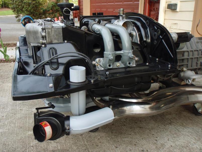 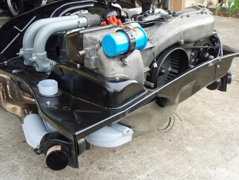 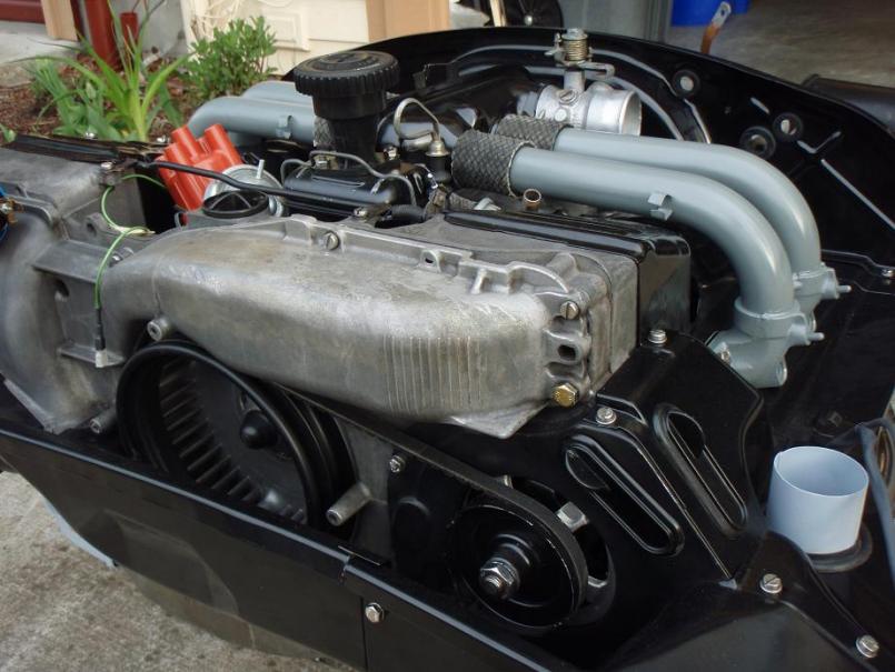
|
|
|
|
| Phoenix914 |
Apr 19 2010, 09:00 AM
Post
#91
|
|
Member Group: Members Posts: 389 Joined: 6-December 06 From: Oviedo, FL Member No.: 7,322 Region Association: South East States |
Your engine is a work of art, my friend. (IMG:style_emoticons/default/aktion035.gif)
|
|
|
|
| rwilner |
Sep 26 2011, 07:08 PM
Post
#92
|
|
No Ghosts in the Machine Group: Members Posts: 953 Joined: 30-March 10 From: Boston, MA Member No.: 11,530 Region Association: North East States |
I am unearthing this thread for 2 reasons
1) this member made some difficult to find heater branch gaskets out of cork that look like they work well 2) what a gorgeous engine. |
|
|
|
|
1 User(s) are reading this topic (1 Guests and 0 Anonymous Users)
0 Members:

|
Lo-Fi Version | Time is now: 1st July 2024 - 06:08 AM |
Invision Power Board
v9.1.4 © 2024 IPS, Inc.