|
|
|
Porsche, and the Porsche crest are registered trademarks of Dr. Ing. h.c. F. Porsche AG.
This site is not affiliated with Porsche in any way. Its only purpose is to provide an online forum for car enthusiasts. All other trademarks are property of their respective owners. |
|
|

  |

| Spoke |
 Apr 14 2012, 09:06 AM Apr 14 2012, 09:06 AM
Post
#281
|
|
Jerry  Group: Members Posts: 7,145 Joined: 29-October 04 From: Allentown, PA Member No.: 3,031 Region Association: None |
Got the seat adjust bracket remounted.
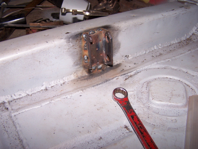 So I cut the hole for the e-brake warning light before mounting the crossbrace and survey says I missed the correct position. (IMG:style_emoticons/default/poke.gif) I cut a new hole with my Dremel and welded the scab piece back in the original hole location. (IMG:style_emoticons/default/sawzall-smiley.gif) 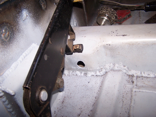 |
   |

 
|
| Spoke |
Apr 14 2012, 09:15 AM
Post
#282
|
|
Jerry Group: Members Posts: 7,145 Joined: 29-October 04 From: Allentown, PA Member No.: 3,031 Region Association: None |
Finished welding in my Engman's inner long kit on the back and the driver's side. Took my time welding so as to not twist the chassis. (IMG:style_emoticons/default/piratenanner.gif)
I'm now finished with the interior de-rusting so I rattle canned the floor and firewall. 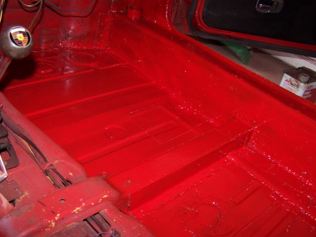 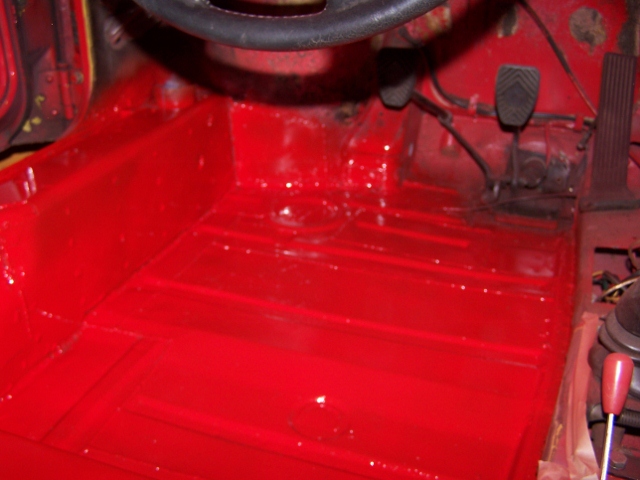 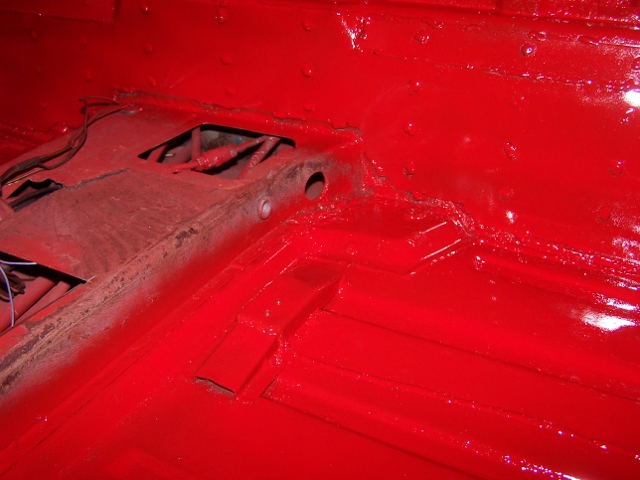 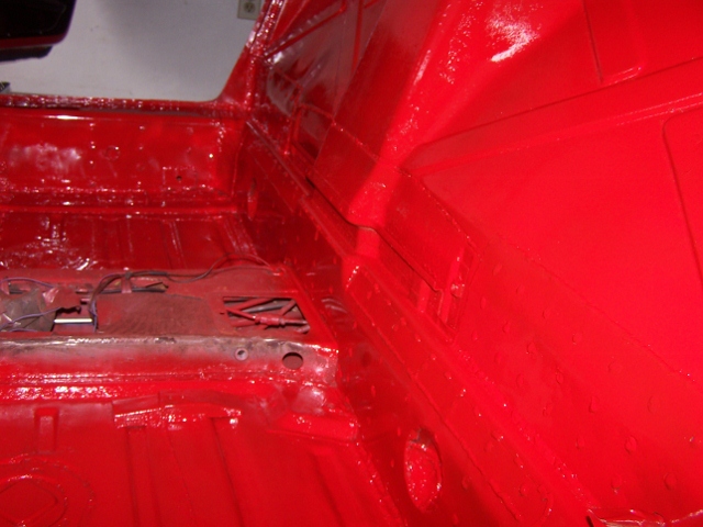 I never liked the little channel for the e-brake cable to transition through so I will try a different method to get the cable to turn. I welded a bolt onto a piece of 14ga steel then to floor and I will put a nylon wheel to allow the cable to move back and forth. 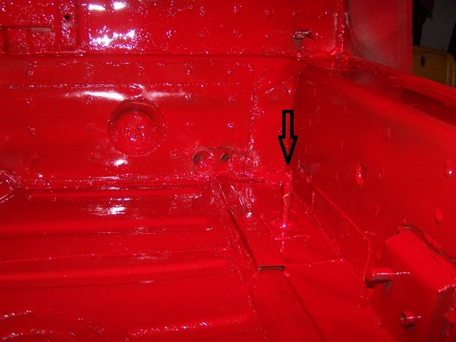 |
|
|
|
| Spoke |
Apr 16 2012, 07:12 PM
Post
#283
|
|
Jerry Group: Members Posts: 7,145 Joined: 29-October 04 From: Allentown, PA Member No.: 3,031 Region Association: None |
When I cut the tunnel open to repair the clutch tube, I decided not to weld the holes shut so I made panels and attached by speed screws. I used the pieces I cut out to help center the panels.
Attached image(s) 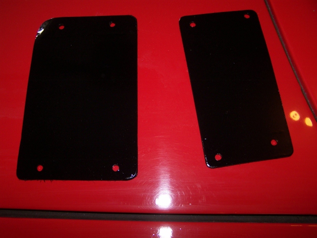 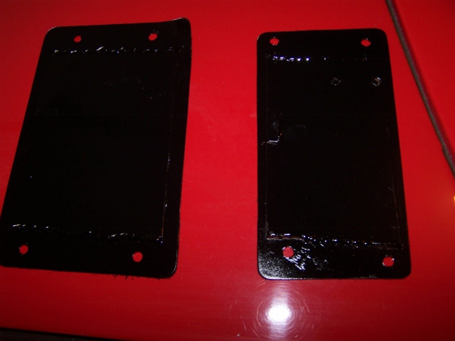
|
|
|
|
| Spoke |
Apr 16 2012, 07:20 PM
Post
#284
|
|
Jerry Group: Members Posts: 7,145 Joined: 29-October 04 From: Allentown, PA Member No.: 3,031 Region Association: None |
Here's my solution to getting rid of the ebrake channel to turn the cable towards the firewall interface.
The bolt is welded to a 14ga plate then to the floor. The roller is free to turn on the sleeve. Works very well with virtually no deflection when the ebrake is pulled to its max. Attached image(s) 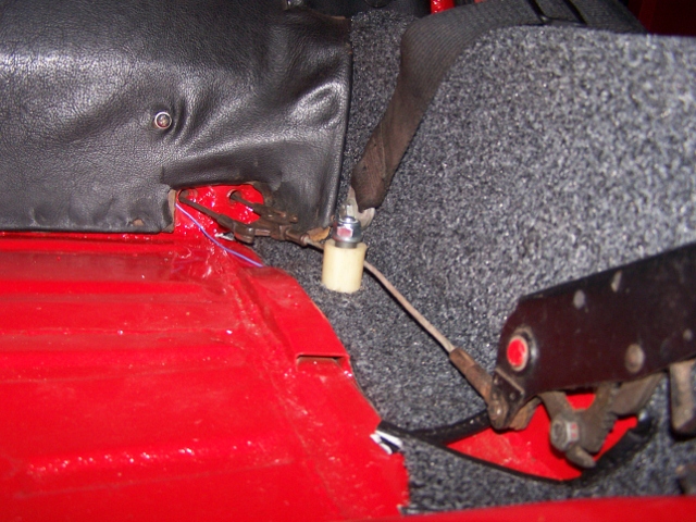 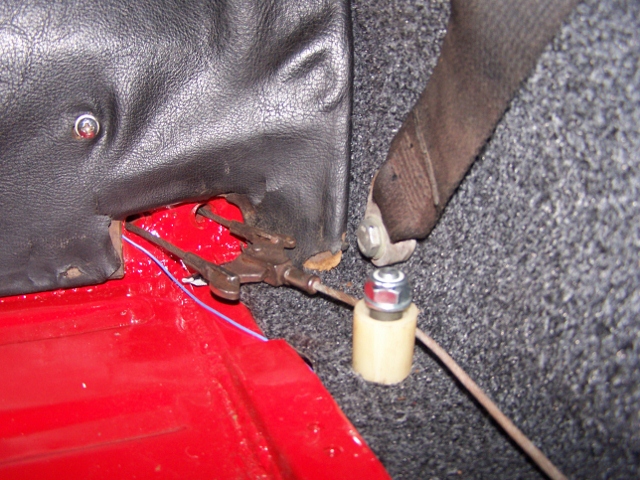 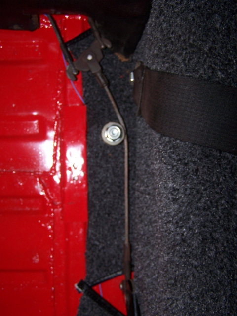
|
|
|
|
| Spoke |
Apr 16 2012, 08:18 PM
Post
#285
|
|
Jerry Group: Members Posts: 7,145 Joined: 29-October 04 From: Allentown, PA Member No.: 3,031 Region Association: None |
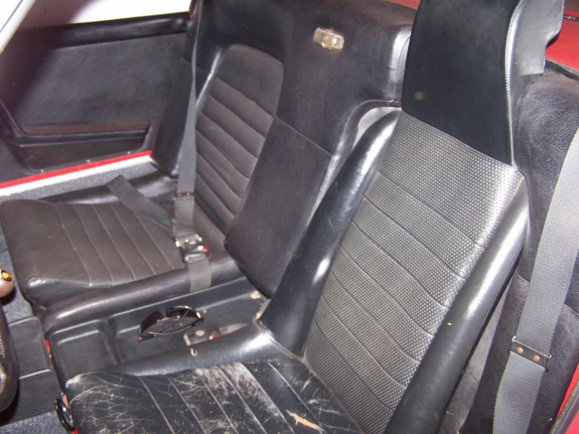
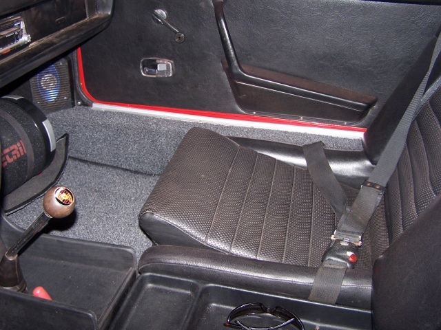
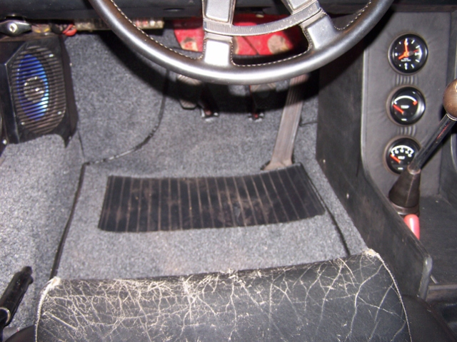
Installed the new carpet kit and put the interior back together.
   |
|
|
|
| jls914 |
Aug 23 2012, 07:00 PM
Post
#286
|
|
Newbie Group: Members Posts: 8 Joined: 23-August 12 From: wendell, NC Member No.: 14,842 Region Association: None |
Spoke,
Came across your posting while searching for fuel pump relocation info. Very nice indeed!! You sure put alot of time and love into this 914. Can you tell me what fuel pump you used and detail the hose connections from bulkhead, tank and pump? I want to update mine as well using a 2 port pump. I would appreciate your input. Thanks, Jim |
|
|
|
| Spoke |
Aug 24 2012, 04:19 AM
Post
#287
|
|
Jerry Group: Members Posts: 7,145 Joined: 29-October 04 From: Allentown, PA Member No.: 3,031 Region Association: None |
Jim,
First off, (IMG:style_emoticons/default/welcome.png) You should start a thread about your car, post pics and ask questions there. You will get a wider response from the World that way. The fuel pump is the later 2 port type. From the fuel tank large port, run to a filter, then to the pump inlet (larger port). From the pump outlet, to one of the center tunnel fuel lines to the engine. Then return back from the engine in the other center tunnel fuel line and into the tank smaller port. Pretty simple. I'm assuming you have fuel injection and not carburetors. |
|
|
|
| jls914 |
Aug 24 2012, 06:03 AM
Post
#288
|
|
Newbie Group: Members Posts: 8 Joined: 23-August 12 From: wendell, NC Member No.: 14,842 Region Association: None |
Thanks. Can you tell me where is the best place to buy the pump? Manufacturer, model#, etc. I am moving and once my garage is complete, I'll bring my '73 and start a thread about it. It is stock and has fuel injection. I moved my old pump up front, but my first pump leaked through the check valve and my second pump leaks out of the body. This is why I want to go to a newer, cheaper and readily available pump and dothe complete re-plumbing job. Again, thanks for the info.
Jim |
|
|
|
| Spoke |
Nov 8 2012, 11:44 AM
Post
#289
|
|
Jerry Group: Members Posts: 7,145 Joined: 29-October 04 From: Allentown, PA Member No.: 3,031 Region Association: None |
Getting ready to convert to 5-lug. Will be doing the work next week while I have a bit of time.
Front end is from a 72 911 with M calipers. Rear end is using the hub from the 72 911 with vented rotors, widened 914 rear calipers and cut (by Eric Shea) rear 911 rotors. 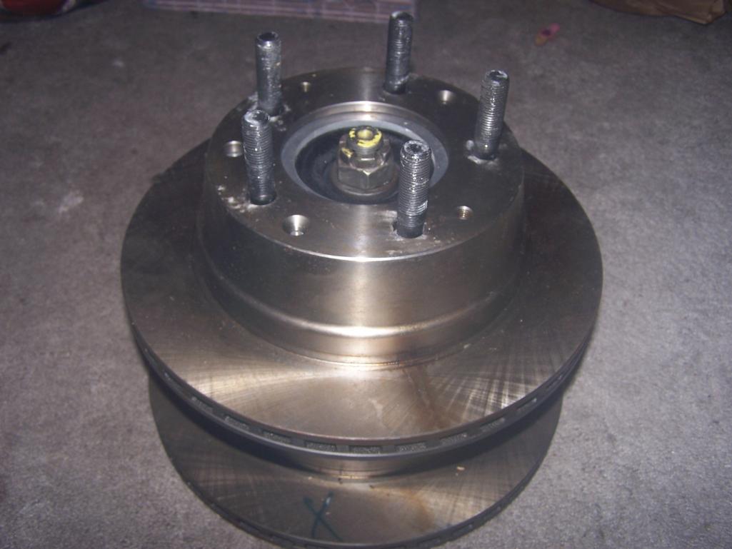 I had to replace the stock studs with the vented rotors so I went with 66mm studs which provide more than adequate threads. 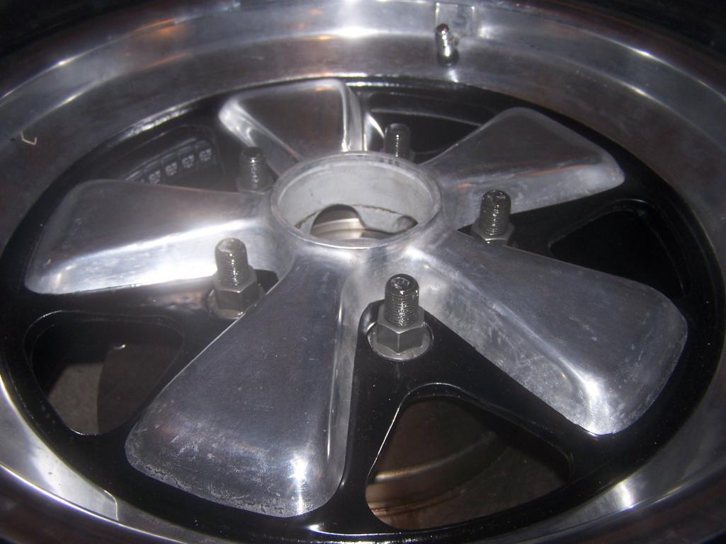 Tires are Riken Raptors; 205/50/16 on 6x16 for the front; 225/50/16 on 7x16 on the rear; and 195/60/14 on 5.5x14 for the spare. 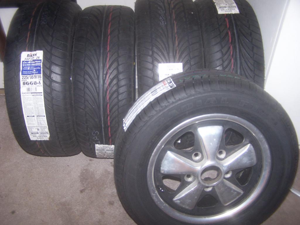 Very nice caliper pad retaining clips from Eric Shea at PMB. 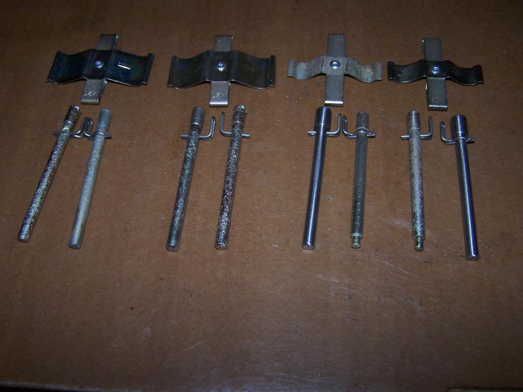 |
|
|
|
| Spoke |
Nov 11 2012, 03:47 PM
Post
#290
|
|
Jerry Group: Members Posts: 7,145 Joined: 29-October 04 From: Allentown, PA Member No.: 3,031 Region Association: None |
The 5-lug process has begun. Doing the front end first.
Started with the drivers front. These replicas will be for sale soon. It scares the crap out of me to get under or even beside the car with the entire front off the ground. I used 2 jackstands on each side along with the floor jack. Attached thumbnail(s) 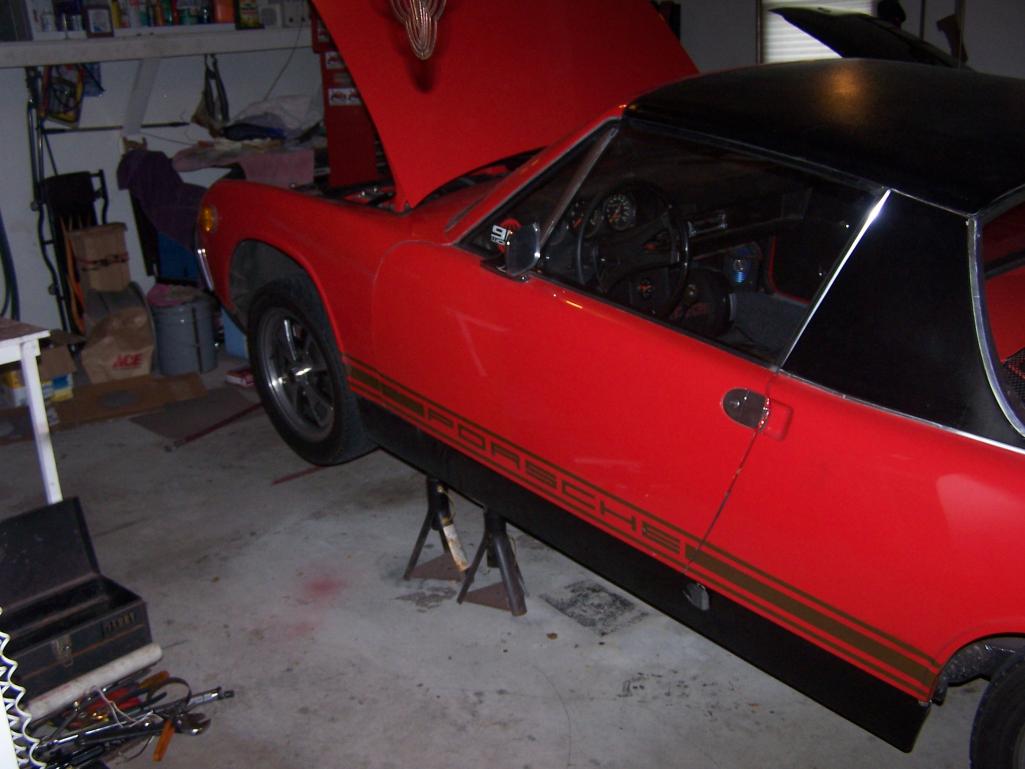 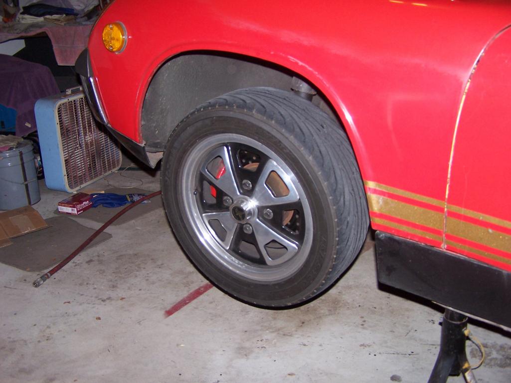
|
|
|
|
| Spoke |
Nov 11 2012, 03:51 PM
Post
#291
|
|
Jerry Group: Members Posts: 7,145 Joined: 29-October 04 From: Allentown, PA Member No.: 3,031 Region Association: None |
Drivers front is done. Got big boy pants on now.
Eric Shea restored calipers are pretty. (IMG:style_emoticons/default/wub.gif) Attached thumbnail(s) 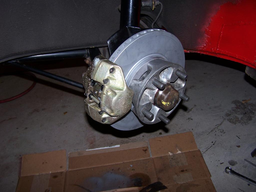 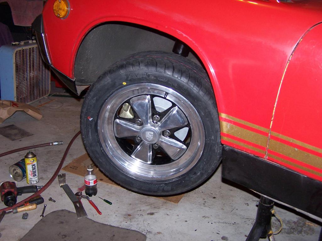
|
|
|
|
| Spoke |
Nov 17 2012, 12:07 PM
Post
#292
|
|
Jerry Group: Members Posts: 7,145 Joined: 29-October 04 From: Allentown, PA Member No.: 3,031 Region Association: None |
Started working on the rear suspension when I had my "oh shit" moment.
After reading all the threads on converting the rear to 5-lug using 911 hubs like I had, I absorbed absolutely none of the facts of what I needed to do to use the 911 hubs. That is until I removed the half-shafts from the car and compared the 914 hub to the 911 hub. Then it all came crashing down. I needed to get different shafts and trans flanges. At that point I decided to go with drilled 914 hubs and use screw-in inserts and sell the 911 hubs/spline/CVs (they are sold). Eric Shea provided some beautifully drilled and tapped hubs. I'm using these 65mm race studs from: 65mm ACS Race Stud Attached thumbnail(s)  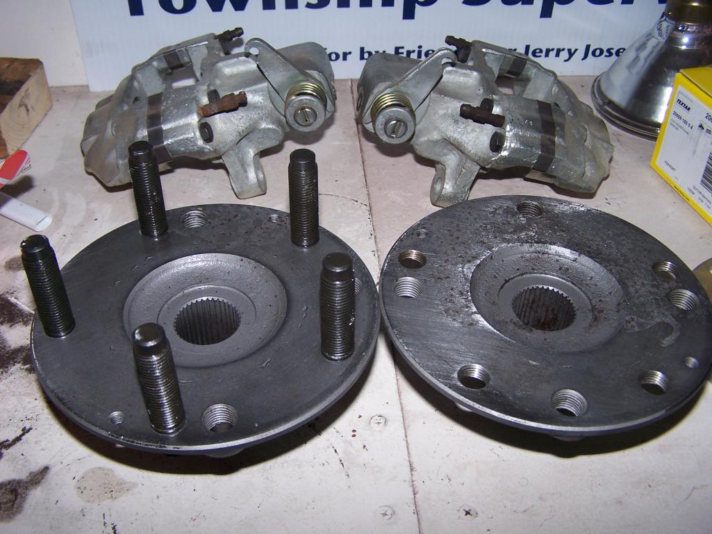
|
|
|
|
| sixnotfour |
Nov 17 2012, 12:41 PM
Post
#293
|
|
914 Wizard Group: Members Posts: 10,764 Joined: 12-September 04 From: Life Elevated..planet UT. Member No.: 2,744 Region Association: Rocky Mountains |
wow, perfect timing or JIT. (IMG:style_emoticons/default/smile.gif)
|
|
|
|
| Spoke |
Nov 17 2012, 08:23 PM
Post
#294
|
|
Jerry Group: Members Posts: 7,145 Joined: 29-October 04 From: Allentown, PA Member No.: 3,031 Region Association: None |
Put the rear swing arms back together.
Freeze the bearings in the freezer and heated the arm with a heat gun on low. The bearings dropped right in without outside force. 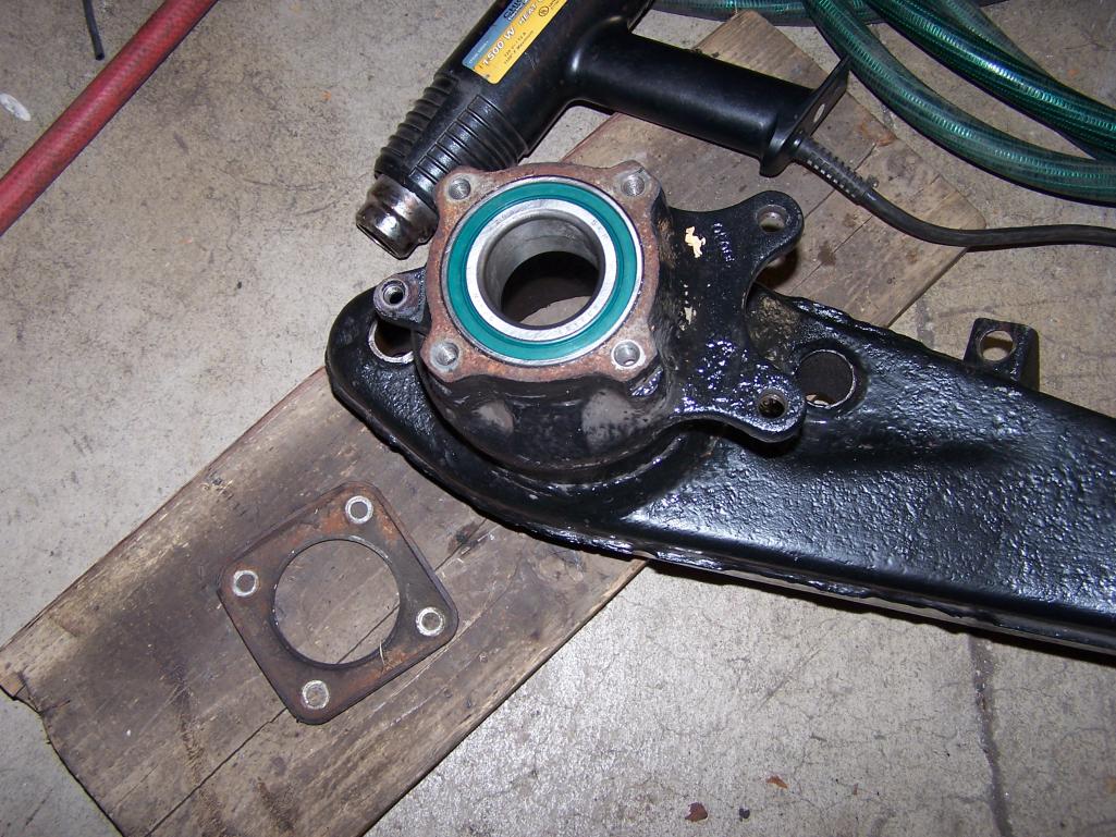 Freeze the hubs in the freezer and heated the arm & bearings with a heat gun on low. Ratcheted the hubs right in with very little force. 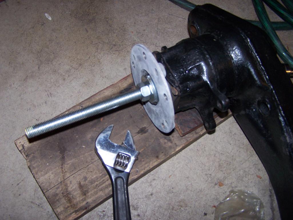 |
|
|
|
| Spoke |
Nov 18 2012, 10:36 AM
Post
#295
|
|
Jerry Group: Members Posts: 7,145 Joined: 29-October 04 From: Allentown, PA Member No.: 3,031 Region Association: None |
While I'm in there:
Always had a bit of a backfire as well as cylinder noise on the drivers side proportional to the throttle position. Figured it some exhaust leak. Here's the culprit: broken weld on #1 exhaust tube. The opposite bolt was loose as well. Attached thumbnail(s) 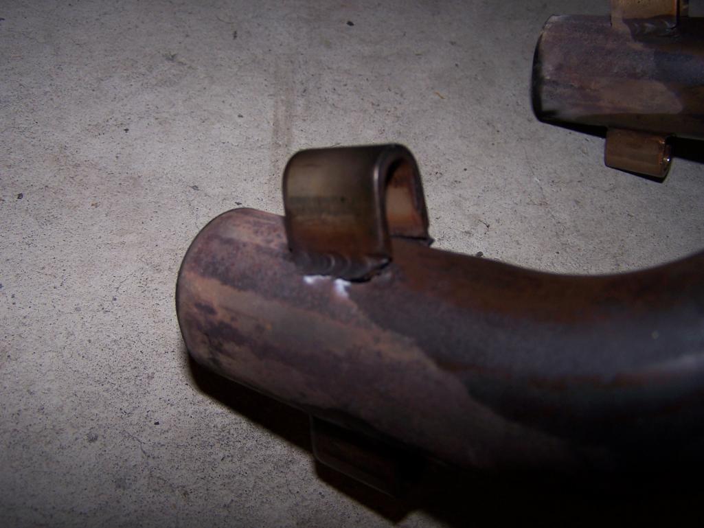
|
|
|
|
| Spoke |
Nov 21 2012, 05:59 PM
Post
#296
|
|
Jerry Group: Members Posts: 7,145 Joined: 29-October 04 From: Allentown, PA Member No.: 3,031 Region Association: None |
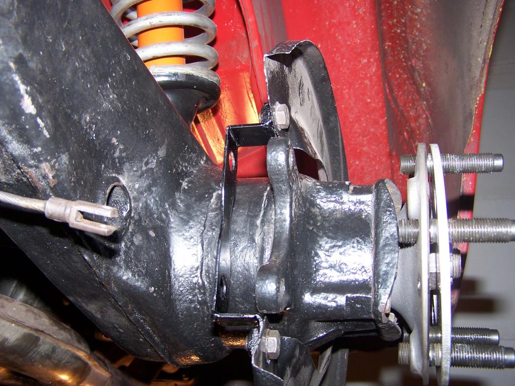
These pics are the same as in my other thread about vented rear rotors.
This first fitment with the rock shield bracket under the caliper mount shows the caliper not centered on the rotor. According to Eric Shea, the rock shield is required for road use but the bracket cannot be under the caliper mount. 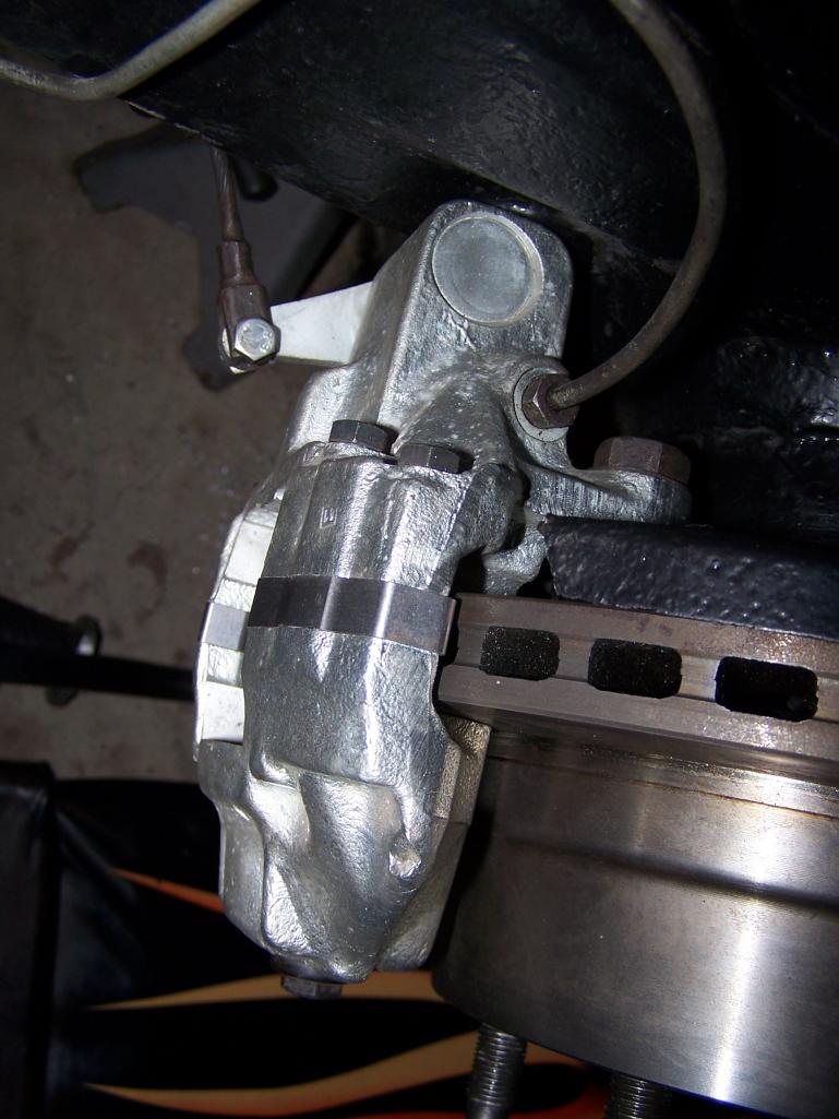 Here's the proper fitment with the caliper mount fastened to the swing arm ear. 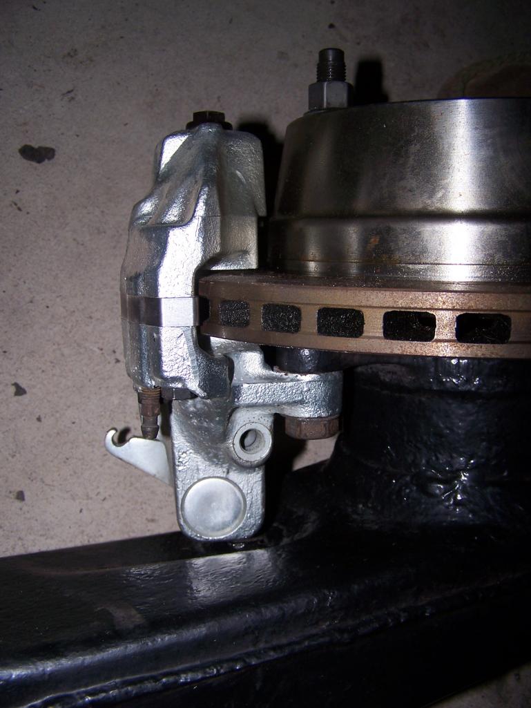 I still needed the rock shield so I modified the bracket to go on the top of the caliper mount. 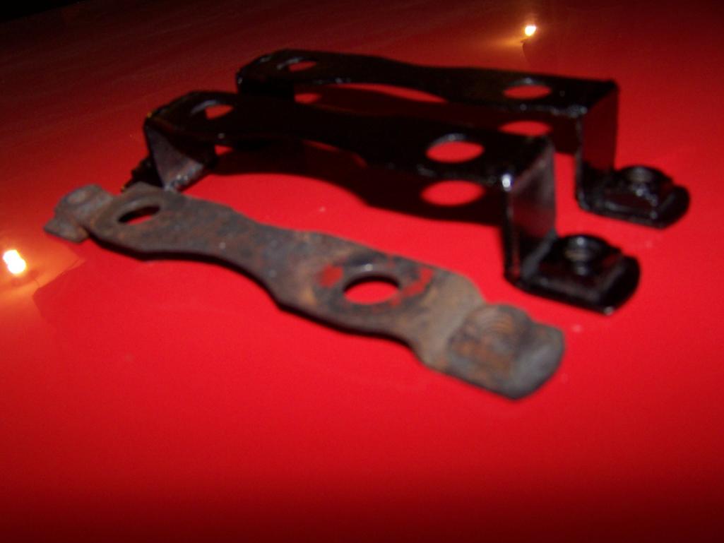 To mount the rock shield on top of the caliper mount, a little of the caliper webbing needs to be filed. 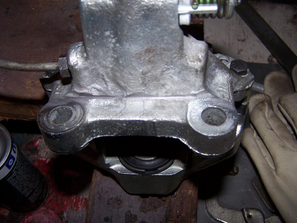 |
|
|
|
| Spoke |
Nov 21 2012, 06:05 PM
Post
#297
|
|
Jerry Group: Members Posts: 7,145 Joined: 29-October 04 From: Allentown, PA Member No.: 3,031 Region Association: None |
Here is the modified rock shield bracket ready for the caliper.
 With the rock shield bracket on top of the caliper mount, the caliper is properly spaced about the rotor. 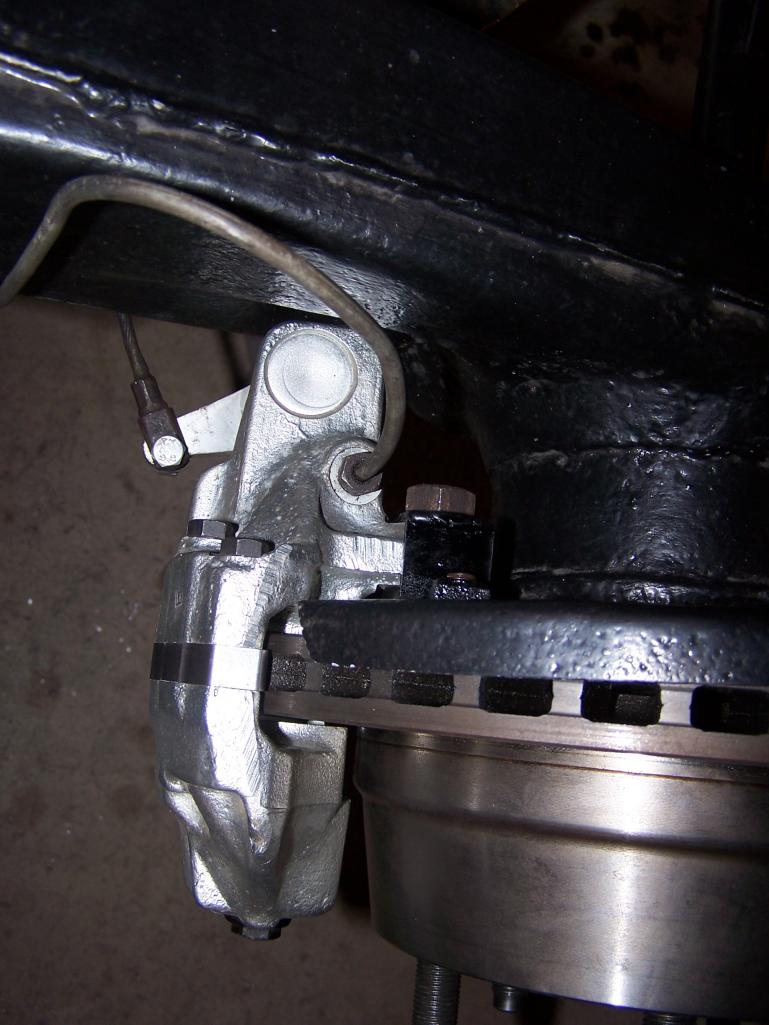 |
|
|
|
| Spoke |
Nov 21 2012, 06:10 PM
Post
#298
|
|
Jerry Group: Members Posts: 7,145 Joined: 29-October 04 From: Allentown, PA Member No.: 3,031 Region Association: None |
Had to pull the fenders out on each side. Have just a bit of room. I'll need to roll the fenders a little more then smooth out the wrinkles.
Love the big boy wheels and tires on the back. (IMG:style_emoticons/default/wub.gif) Attached thumbnail(s) 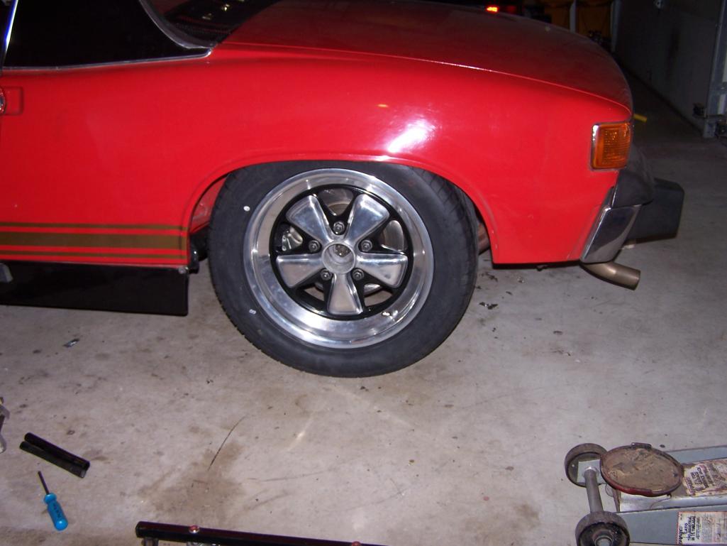 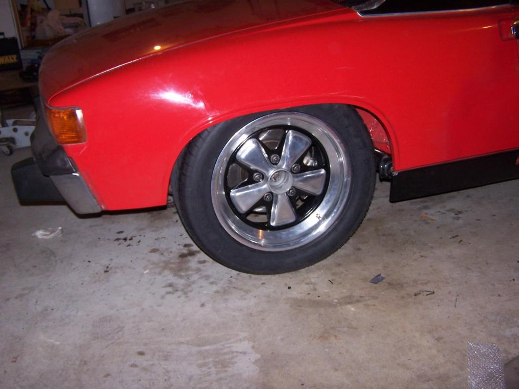 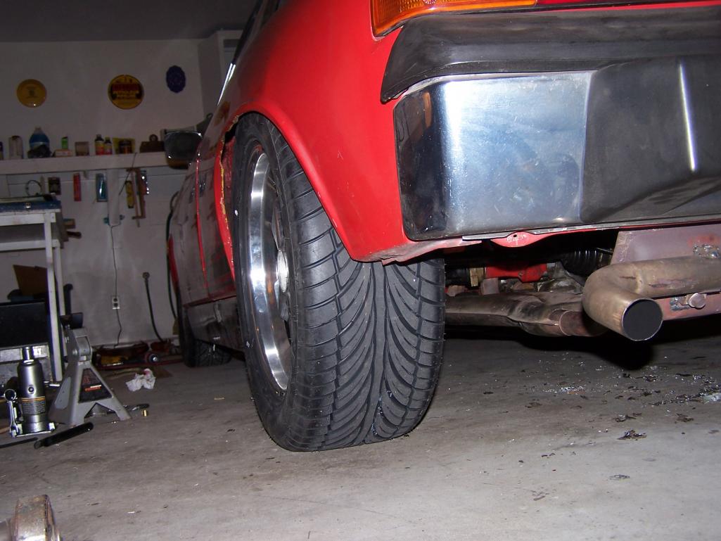 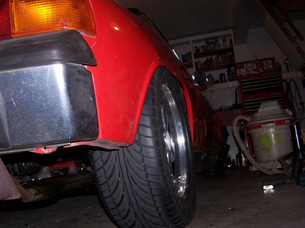
|
|
|
|
| Chi Town |
Feb 3 2013, 06:18 PM
Post
#299
|
|
Newbie Group: Members Posts: 4 Joined: 26-January 13 From: Denver, CO Member No.: 15,430 Region Association: Rocky Mountains |
I just read your entire thread...Amazing work!!
|
|
|
|
| Spoke |
Sep 1 2013, 07:44 PM
Post
#300
|
|
Jerry Group: Members Posts: 7,145 Joined: 29-October 04 From: Allentown, PA Member No.: 3,031 Region Association: None |
Time to debounce the tachometer. I'm tired of seeing the tach needle bounce all over the place when I shift gears or rev the engine.
The 914 tach is underdamped meaning the tachometer will respond quickly to changes in RPM but will oscillate after the change and settle to the correct RPM. Something like the red line below is desired. The tach will respond a bit lower to quick jabs of the throttle but should not bounce or oscillate upon every RPM change. 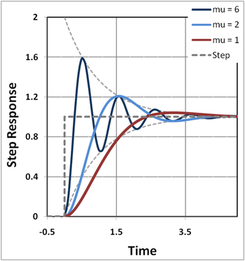 Here's a quick video of the tach without damping. Standard Tach Performance An easy way to damp is to add a capacitor directly across the winding of the needle armature. I've found that early tachs have a more complicated circuit and simply adding a cap across the armature not only settles the needle but causes the needle to read about 1.5x the actual RPM. So I purchased a 74+ tach and added a 2200uF capacitor across the armature. The cap was just hot-melt glued into place and 2 wires soldered to the circuit board of the tach. 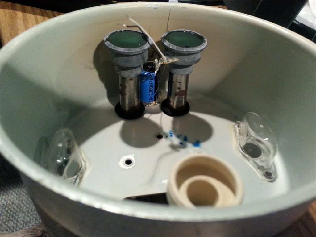 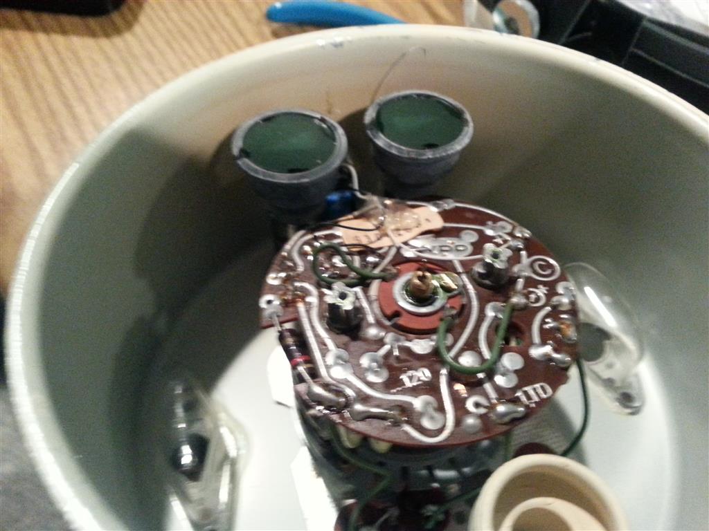 Here's a video of the tach with the 2200uF cap installed. The tach is much more damped and doesn't wildly overshoot like before. After Compensation |
|
|
|
|
1 User(s) are reading this topic (1 Guests and 0 Anonymous Users)
0 Members:

|
Lo-Fi Version | Time is now: 2nd April 2025 - 11:39 PM |
Invision Power Board
v9.1.4 © 2025 IPS, Inc.