|
|

|
Porsche, and the Porsche crest are registered trademarks of Dr. Ing. h.c. F. Porsche AG.
This site is not affiliated with Porsche in any way. Its only purpose is to provide an online forum for car enthusiasts. All other trademarks are property of their respective owners. |
|
|
  |
| 3d914 |
 Feb 13 2013, 10:26 PM Feb 13 2013, 10:26 PM
Post
#241
|
|
Senior Member    Group: Members Posts: 1,275 Joined: 24-September 03 From: Benson, AZ Member No.: 1,191 Region Association: Southwest Region |
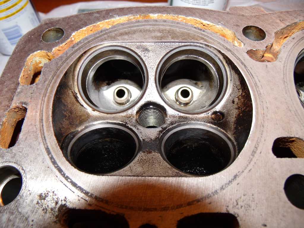
OK, got the first six valves done on the right head. They really needed lapping. Guess I should of done this initially. Got some nice clean seats now. Had to post a pic.
 |
| 3d914 |
 Feb 18 2013, 01:21 PM Feb 18 2013, 01:21 PM
Post
#242
|
|
Senior Member    Group: Members Posts: 1,275 Joined: 24-September 03 From: Benson, AZ Member No.: 1,191 Region Association: Southwest Region |
Spent part of the weekend pulling the left head. Got all the valve hardware off. The exhaust seals were shot on this side also. Will get the valves lapped this week and be ready to thoroughly clean the heads this weekkend before reassembly.
Decided to remount the heads after installing seals to get compression for each cylinder. Will decide about pullling cylinders & rings based on that. |
| 914GT |
 Feb 18 2013, 05:48 PM Feb 18 2013, 05:48 PM
Post
#243
|
|
Senior Member    Group: Members Posts: 1,101 Joined: 11-October 04 From: Tucson Member No.: 2,923 Region Association: Southwest Region |
Were your valve guides in good condition?
Guy |
| 3d914 |
 Feb 24 2013, 03:27 PM Feb 24 2013, 03:27 PM
Post
#244
|
|
Senior Member    Group: Members Posts: 1,275 Joined: 24-September 03 From: Benson, AZ Member No.: 1,191 Region Association: Southwest Region |
Were your valve guides in good condition? Guy Guy, Yes, there was no "additional" air when I tested the intake pressure before tear down, and no noticable slop on any of the valves in the guides. I'm still waiting for valve seals to arrive. Cleaned up the right head, and pulling the engine/tranny off the cradle so the block can be installed on an engine stand. 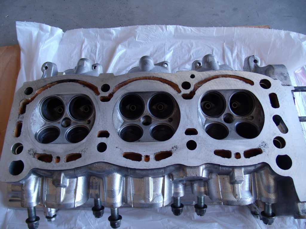 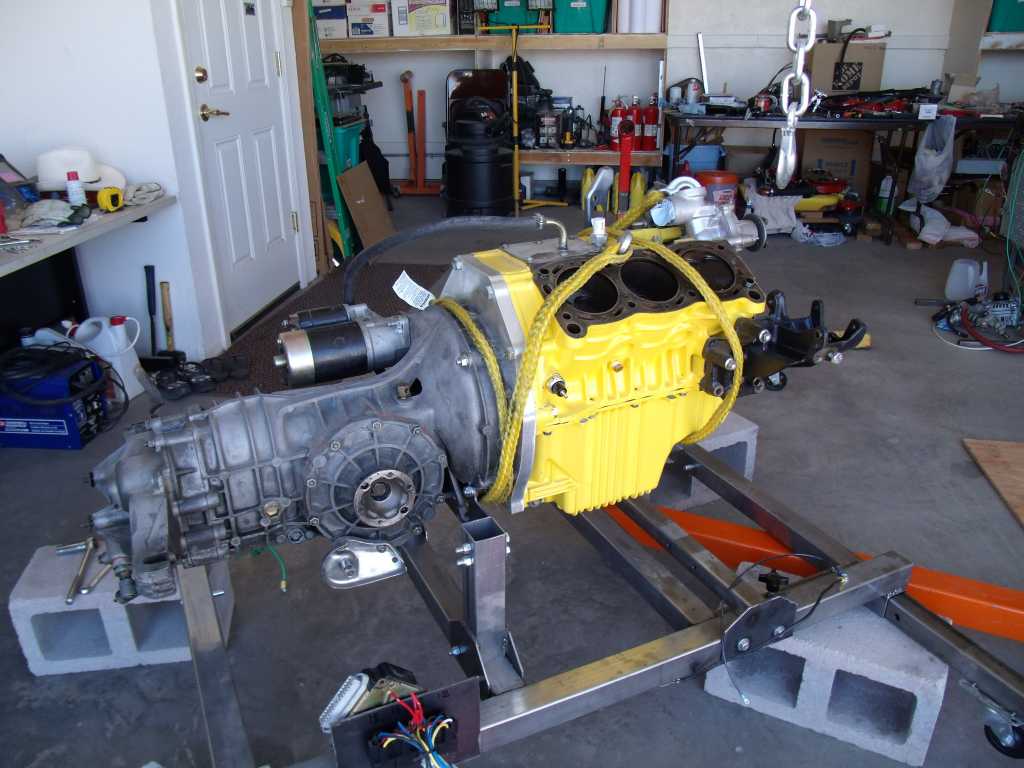 |
| 3d914 |
 Mar 3 2013, 06:50 PM Mar 3 2013, 06:50 PM
Post
#245
|
|
Senior Member    Group: Members Posts: 1,275 Joined: 24-September 03 From: Benson, AZ Member No.: 1,191 Region Association: Southwest Region |
About all I got done this weekend was to clean up the left head. Got some sinus infection & its been slowing me down. The seals came in, but before I work on those I need to get the engine block up off the floor and onto a stand.
|
| 3d914 |
 Mar 4 2013, 08:35 PM Mar 4 2013, 08:35 PM
Post
#246
|
|
Senior Member    Group: Members Posts: 1,275 Joined: 24-September 03 From: Benson, AZ Member No.: 1,191 Region Association: Southwest Region |
Finally pulled the tranny, clutch assy, and flywheel off.
Did notice on the flywheel that the starter teeth don't seem to be engaging fully - only about 1/4 the tooth. I'll have to contact Kennedy to see what they say. 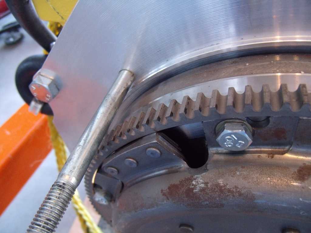 |
| 3d914 |
 Mar 8 2013, 11:11 PM Mar 8 2013, 11:11 PM
Post
#247
|
|
Senior Member    Group: Members Posts: 1,275 Joined: 24-September 03 From: Benson, AZ Member No.: 1,191 Region Association: Southwest Region |
Just an update. The tear down is proving to be a slippery slope. First bad valve seals - not too bad. Pulled pistons to check them - only a couple of partially stuck rings. Checked the ring gaps - way out of spec. So that means at least a new ring set.
Now I'll have to measure the cylinders to see if they're within spec or not - and may have to go over-sized. This is just too much fun - think I need a break! |
| 914GT |
 Mar 9 2013, 09:05 AM Mar 9 2013, 09:05 AM
Post
#248
|
|
Senior Member    Group: Members Posts: 1,101 Joined: 11-October 04 From: Tucson Member No.: 2,923 Region Association: Southwest Region |
Well you could always bring it up to Doc's machine shop in Tucson and simply write him a check (IMG:style_emoticons/default/smile.gif)
|
| 3d914 |
 Mar 9 2013, 05:39 PM Mar 9 2013, 05:39 PM
Post
#249
|
|
Senior Member    Group: Members Posts: 1,275 Joined: 24-September 03 From: Benson, AZ Member No.: 1,191 Region Association: Southwest Region |
Guy, have you used them before? I may have to have the cylinders oversized. Got a micrometer on order so I won't know for a while.
|
| 3d914 |
 Mar 10 2013, 03:34 PM Mar 10 2013, 03:34 PM
Post
#250
|
|
Senior Member    Group: Members Posts: 1,275 Joined: 24-September 03 From: Benson, AZ Member No.: 1,191 Region Association: Southwest Region |
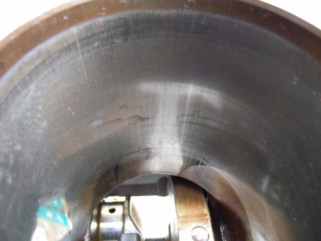
Since my micrometer is on order, I decided to use the ring gap as a gauge for preliminary cylinder bore taper measurements. Took the top ring from piston #1 to use for all cylinders in three locations along each bore. I was also able to inspect the cylinders better with some daylight. I don't see any traces of cross-hatching in any of the cylinders (pics included).
Here's the preliminary taper results and pics. Cylinder #1:
 |
| Mike Bellis |
 Mar 10 2013, 03:43 PM Mar 10 2013, 03:43 PM
Post
#251
|
|
Resident Electrician      Group: Members Posts: 8,347 Joined: 22-June 09 From: Midlothian TX Member No.: 10,496 Region Association: None 

|
I think you should hone the walls, get new rings and get it running! (IMG:style_emoticons/default/driving.gif)
|
| 914GT |
 Mar 10 2013, 06:16 PM Mar 10 2013, 06:16 PM
Post
#252
|
|
Senior Member    Group: Members Posts: 1,101 Joined: 11-October 04 From: Tucson Member No.: 2,923 Region Association: Southwest Region |
Must not have been much of a ridge at the top of the cylinders if you got the pistons out without cutting it down. So as Mike said you might get away with freshening up the cylinders with a hone and new rings.
I've had Docs (real name Bruce, his dad went by Doc) do my machine shop work for probably 20 years or more. He's done full engine block work, heads, and we rebuilt the old 2.0 that was in my 914. He did a lot of friction/thermal coating for me also. Most recent job I had for hm was boring and honing a block for a jetski a year or so ago. |
| 3d914 |
 Mar 10 2013, 07:30 PM Mar 10 2013, 07:30 PM
Post
#253
|
|
Senior Member    Group: Members Posts: 1,275 Joined: 24-September 03 From: Benson, AZ Member No.: 1,191 Region Association: Southwest Region |
Mike, I hoping that's all that's needed.
Guy, No ridge at all. It's hard to tell from the photos, but there is a slight chamfer at the top of the cylinder. It's different material than cylinder coating. A few of the cyls have slight scrapes in this chamfer, but nothing significant. I was planning to clean these areas up with some light hand sanding and leave it at that. If I get the micrometer by next weekend, I'll get some actual measurements. Maybe I won't need Doc. Wish me luck. |
| 3d914 |
 Mar 17 2013, 03:40 PM Mar 17 2013, 03:40 PM
Post
#254
|
|
Senior Member    Group: Members Posts: 1,275 Joined: 24-September 03 From: Benson, AZ Member No.: 1,191 Region Association: Southwest Region |
I took the nominal bore diameter (3.622) then added the tolerance of .0012" gives me a max diameter of 3.6232".
I made two measurements near the top. One (A) at .25" below the bottom edge of the chamfer - where the cylinder coating material starts. The other (B) is .75" down from the face of the block. This is equivalent to top travel of the oil ring.
|
| 3d914 |
 Mar 19 2013, 07:34 PM Mar 19 2013, 07:34 PM
Post
#255
|
|
Senior Member    Group: Members Posts: 1,275 Joined: 24-September 03 From: Benson, AZ Member No.: 1,191 Region Association: Southwest Region |
OK, got a honing tool on the way and rings ordered. Spent the last two evening getting the seals, valves, and spring assy back in the heads. Ready for cams & seals. Oh shit - gotta order new camshaft seals too!
|
| 3d914 |
 Mar 30 2013, 01:58 PM Mar 30 2013, 01:58 PM
Post
#256
|
|
Senior Member    Group: Members Posts: 1,275 Joined: 24-September 03 From: Benson, AZ Member No.: 1,191 Region Association: Southwest Region |
Well seals came in and got the right head assembled - only to strip threads putting on the #1 bearing cap. Decided to go with 8mm studs to replace the 7mm threads. After drilling the clearance holes I found out why they pulled out - helicoils! I don't know if these ever work - but they certainly don't work in aluminum.
Got nice results from the studs though. Now on the left head. 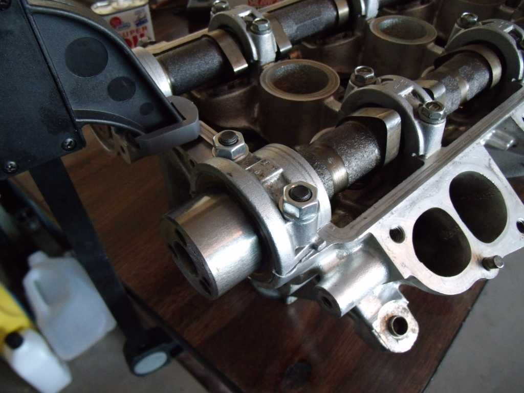 |
| 3d914 |
 Apr 7 2013, 06:36 PM Apr 7 2013, 06:36 PM
Post
#257
|
|
Senior Member    Group: Members Posts: 1,275 Joined: 24-September 03 From: Benson, AZ Member No.: 1,191 Region Association: Southwest Region |
Left head is now completed - cams on, sealed up and ready to go.
Found some used pistons in Tucson. They all measured in at the low end of the clearance range - which works great since I still have to hone the cylinders and will loose a few .0001's. Got DNJ rings ordered, finished assy on the left head, and located some head bolts to replace 5 or 6 of mine that were mucked-up. Hope to be up & running again in a couple of weeks. |
| 3d914 |
 Apr 7 2013, 07:24 PM Apr 7 2013, 07:24 PM
Post
#258
|
|
Senior Member    Group: Members Posts: 1,275 Joined: 24-September 03 From: Benson, AZ Member No.: 1,191 Region Association: Southwest Region |
Spent most the day cleaning used pistons I found in Tucson yesterday. I did get some time to hone at least three of the cylinders. Since my crank is still installed I needed to take extra care to avoid getting material in & around it, but also to limit the mess on the upper parts of the block.
Here's what I came up with. 1) First I taped off the cylinder to be honed. I later modified this and taped off the whole surface for the remaining cyls also. I cut a 13 gallon garbage bag in half and laid it over the one side. 2) I took another garbage bag, folded it a few times so it was the width of the cylinder. This one I draped over the crank to protect it. 3) I also cut a circular piece of heavy cardboard (over-sized for the cyl) and slid it down to the bottom of the cylinder so it could rest on the crank. I didn't want to have the hone hit the crank at all. It was necessary to rotate the crank before doing anything so the big counter-weight was out of the way for that cylinder. As added protection I stuffed a rag between the cardboard and the garbage-bag wrapped crank. This allowed me to be able to slide the hone down until I heard it hit the cardboard. 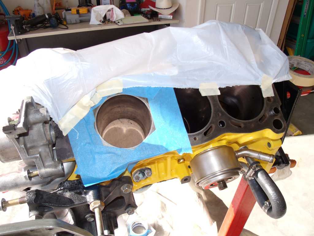 4) I added a third garbage bag and taped the upper two together. Here it is already for surgery. 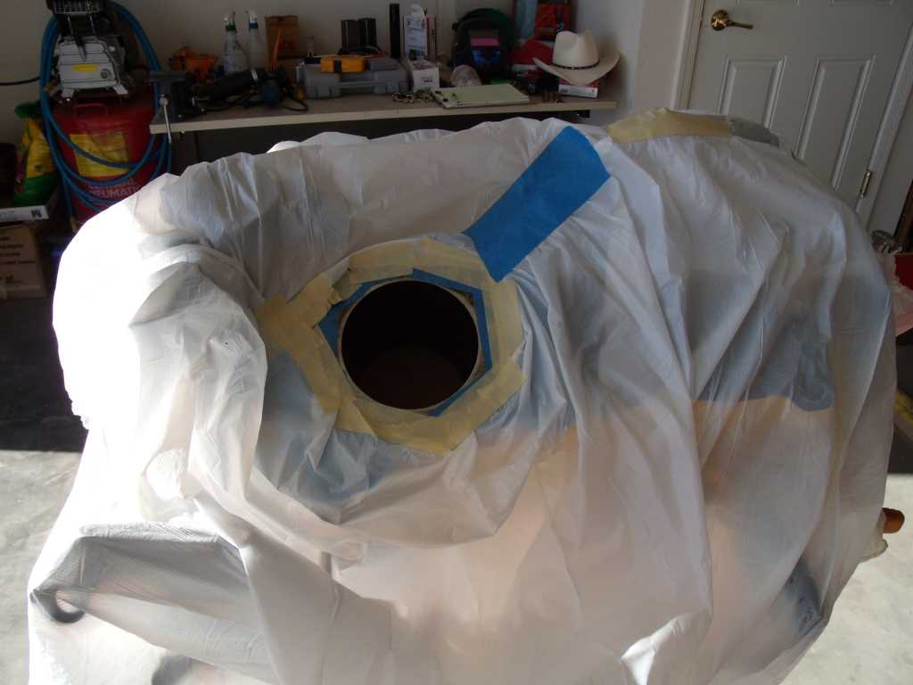 5) Now to keep the oil on the hone from flying everywhere (which turned out wasn't that bad since the drill is used a such low speeds) - I modified a small box I had so that the hone could spin freely in it before entering the piston. The height of the box needs to be around 6.5" for the shorter ball hones. I'm using the 92mm hone. This worked out really well and I had almost no spill-over or mess. 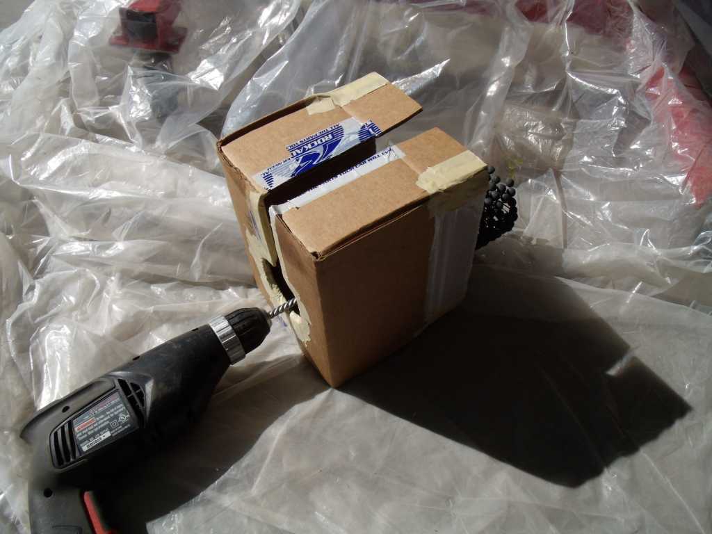 6) As I did each cylinder, I just held the drill in one hand and the box in the other - with the hone positioned inside the box. I lined up the box & hone over the cylinder, set the drill at the correct speed, held the box against the block, and started honing. Here's the results. Even though it's only a light hone, it took 8-10 in & out cycles to get that. The glaze on these cyls must be hard. 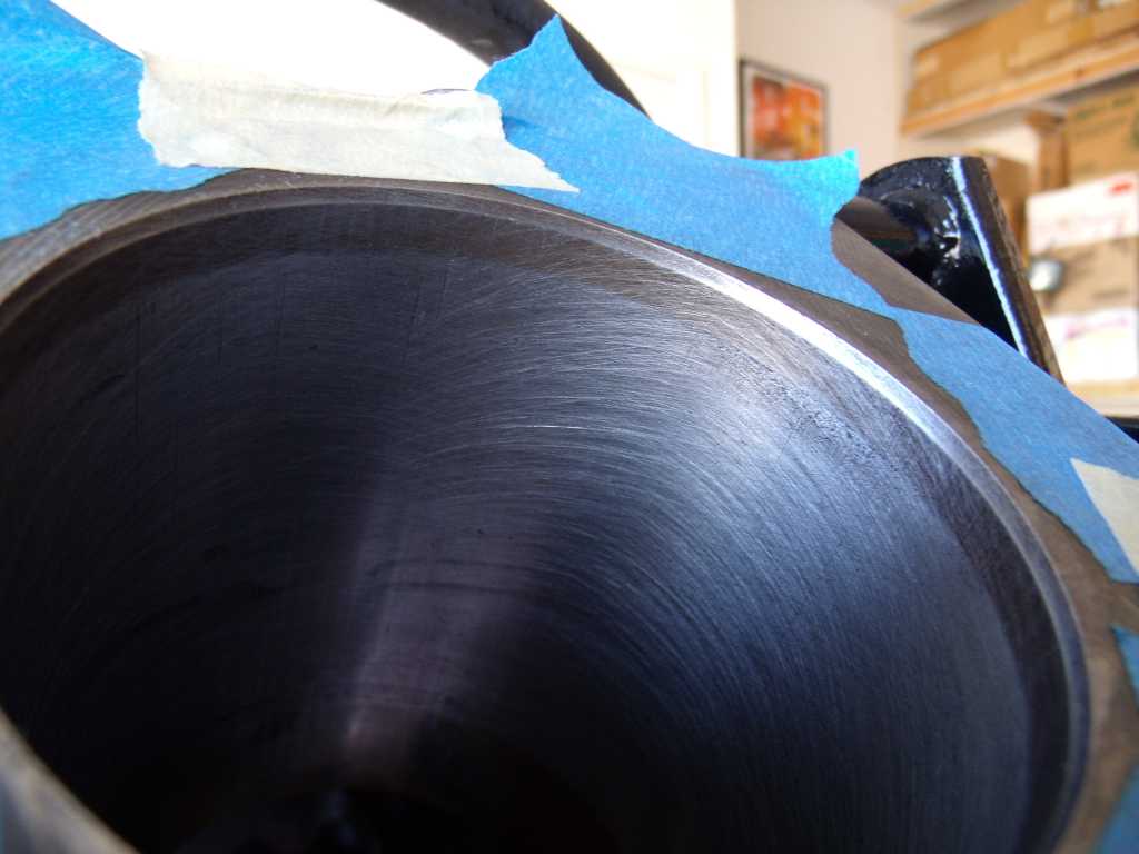 |
| 3d914 |
 Apr 11 2013, 10:35 PM Apr 11 2013, 10:35 PM
Post
#259
|
|
Senior Member    Group: Members Posts: 1,275 Joined: 24-September 03 From: Benson, AZ Member No.: 1,191 Region Association: Southwest Region |
Got the other cyls honed this week, and finally got to fit the new (used) pistons. I think I went from one extreme to the other. Though I'd rather be here. I fit each group of pistons per side (R or L), and I ended up below the clearance using a feeler gauge.
I'll do more accurate measuring tomorrow with the micrometer. Here's the cyl-piston gaps I get with the feeler gauge:
If they come out nearly the same after the mic, I'll just go back and do some more honing. |
| 3d914 |
 Apr 13 2013, 08:57 PM Apr 13 2013, 08:57 PM
Post
#260
|
|
Senior Member    Group: Members Posts: 1,275 Joined: 24-September 03 From: Benson, AZ Member No.: 1,191 Region Association: Southwest Region |
HooRa! (IMG:style_emoticons/default/piratenanner.gif) Pistons are back in.
First I did a test fit of each piston in the cylinder. Each had smooth movement up & down the cylinder. I didn't have the rod cap on so I was just letting the piston gravity drop on the down side - without rings in. Everything looked good, so I continued to check the ring gaps. Results looked great here too - no grinding required.
Then on with the installation. Right side: 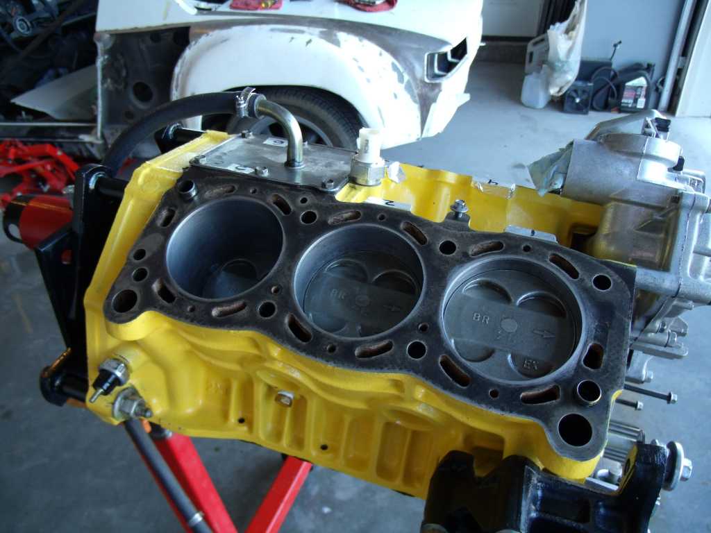 Left side: All cleaned up and ready for heads - just waiting on half-dozen replacement head bolts. But I can get the bottom end/oil pan all closed up. 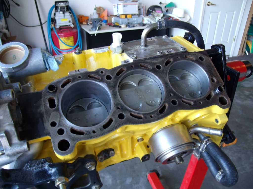 |
  |
1 User(s) are reading this topic (1 Guests and 0 Anonymous Users)
0 Members:

|
Lo-Fi Version | Time is now: 19th April 2025 - 02:49 PM |
Invision Power Board
v9.1.4 © 2025 IPS, Inc.


