|
|

|
Porsche, and the Porsche crest are registered trademarks of Dr. Ing. h.c. F. Porsche AG.
This site is not affiliated with Porsche in any way. Its only purpose is to provide an online forum for car enthusiasts. All other trademarks are property of their respective owners. |
|
|
  |
| Dr Evil |
 Nov 21 2010, 05:31 AM Nov 21 2010, 05:31 AM
Post
#641
|
|
Send me your transmission!                Group: Members Posts: 23,038 Joined: 21-November 03 From: Loveland, OH 45140 Member No.: 1,372 Region Association: MidAtlantic Region 
|
some inspiration from our motorcycle friends
Attached image(s) 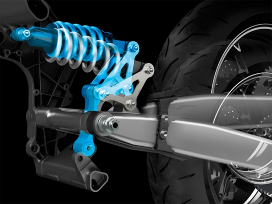 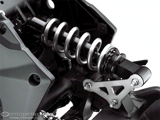
|
| geniusanthony |
 Nov 21 2010, 07:10 AM Nov 21 2010, 07:10 AM
Post
#642
|
|
Its a brand new "Chrome-sicle"    Group: Members Posts: 517 Joined: 12-December 05 From: Alexandria,VA Member No.: 5,266 Region Association: MidAtlantic Region |
What would be the effect of a simple 90 deg bellcrank to transfer vertical motion into horizontal motion? The off center triangle designs exist for the tightest confines and non-linear travel like say bikes and such, like a mechanical means toward progressive action. Please correct me if I am wrong however.
|
| plymouth37 |
 Nov 21 2010, 10:57 AM Nov 21 2010, 10:57 AM
Post
#643
|
|
Senior Member    Group: Members Posts: 1,825 Joined: 24-May 05 From: Snoqualmie, WA Member No.: 4,138 Region Association: Pacific Northwest 
|
This is what I was looking at before, a simple bell crank converting vertical motion to horizontal.
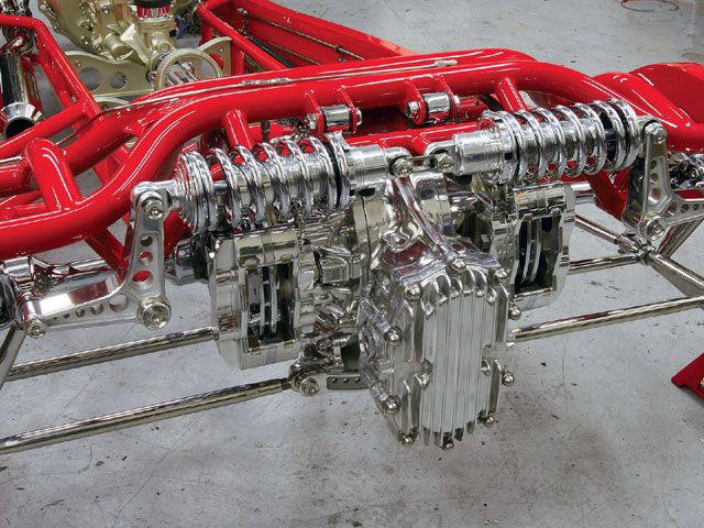 And here was my rendering using this concept. 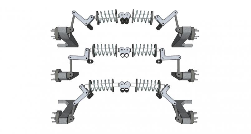 I think this is the most straight forward solution but I was thinking about the offset cantilever because of space restrictions and the fact that the design above has a high center of gravity while the off set one is relatively low. |
| plymouth37 |
 Nov 21 2010, 11:07 AM Nov 21 2010, 11:07 AM
Post
#644
|
|
Senior Member    Group: Members Posts: 1,825 Joined: 24-May 05 From: Snoqualmie, WA Member No.: 4,138 Region Association: Pacific Northwest 
|
How do you guys think the handling would suffer if I went with the offset cantilever option? I think I am fine with the equivalent spring rate acting like a progressive spring adding around 7 pounds of extra spring force per inch of suspension compression, any opinions?
Here it is again for easy reference: 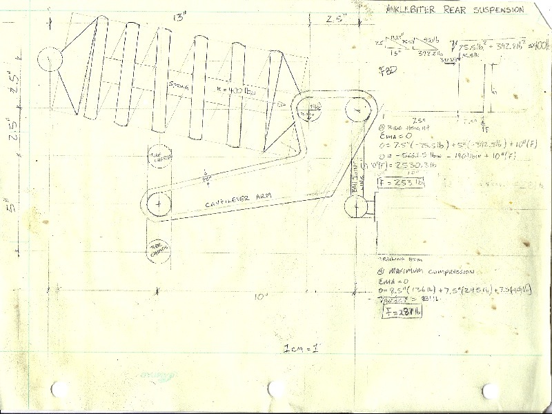 Here is a shot of an aftermarket wrangler suspension that looks similar, granted the Anklebiter will have a slightly different driving experience than this guy... 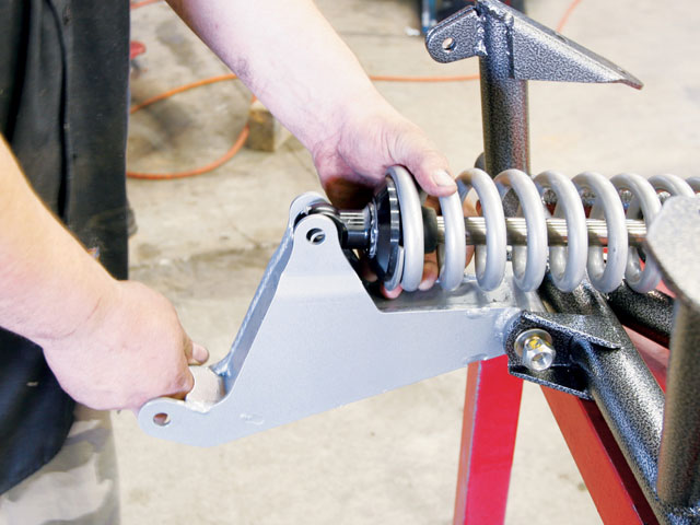 And another similar setup for a Nissan Titan: 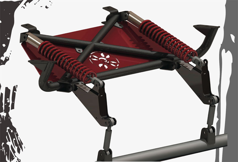 My springs will be pointing towards each other rather than parallel but the lever action will work in the same way. |
| PeeGreen 914 |
 Nov 21 2010, 01:41 PM Nov 21 2010, 01:41 PM
Post
#645
|
|
Just when you think you're done...wait, there is more..lol           Group: Members Posts: 10,219 Joined: 21-September 06 From: Seattle, WA... actually Everett Member No.: 6,884 Region Association: Pacific Northwest 
|
Dana, you make me sick. I love your work. Keep it going. I keep looking at the pictures I took when I was at your house and druel regularly.
|
| jd74914 |
 Nov 21 2010, 03:32 PM Nov 21 2010, 03:32 PM
Post
#646
|
|
Its alive     Group: Members Posts: 4,841 Joined: 16-February 04 From: CT Member No.: 1,659 Region Association: North East States |
How do you guys think the handling would suffer if I went with the offset cantilever option? I think I am fine with the equivalent spring rate acting like a progressive spring adding around 7 pounds of extra spring force per inch of suspension compression, any opinions? My gut reaction is that the progressive change is a non-issue. I'm assuming the springs are maybe 1.5 orders of magnitude stiffer than the progressive increase so it probably will not be very noticeable at all. One suggestion though. You might want to look into adding a bearing at the bellcrank's pivot point. While the car weights and hence suspension forces are radically different, we found the stiction to be pretty [unacceptably] high on our FSAE car with only a bushing. |
| plymouth37 |
 Nov 21 2010, 05:56 PM Nov 21 2010, 05:56 PM
Post
#647
|
|
Senior Member    Group: Members Posts: 1,825 Joined: 24-May 05 From: Snoqualmie, WA Member No.: 4,138 Region Association: Pacific Northwest 
|
One suggestion though. You might want to look into adding a bearing at the bellcrank's pivot point. While the car weights and hence suspension forces are radically different, we found the stiction to be pretty [unacceptably] high on our FSAE car with only a bushing. Good point, I had planned on using a bushing there but was wondering if it was going to be an issue. |
| Bee Jay |
 Nov 23 2010, 01:21 AM Nov 23 2010, 01:21 AM
Post
#648
|
|
Member   Group: Members Posts: 204 Joined: 22-April 05 From: Lompoc, Ca. Member No.: 3,964 |
I just spent two evenings reading all 33 pages. Absolutely amazing work. I'm inspired and motivated.
Bee Jay |
| smontanaro |
 Nov 23 2010, 05:07 AM Nov 23 2010, 05:07 AM
Post
#649
|
|
Senior Member    Group: Members Posts: 1,190 Joined: 3-June 05 From: Evanston, IL Member No.: 4,197 Region Association: Upper MidWest |
I just spent two evenings reading all 33 pages. Don't be fooled. It is actually a clever ploy to soak up our time and keep us from working on or driving our cars. With the cumulative evenings people have spent reading this thread two or three complete cars could have been restored! (IMG:style_emoticons/default/biggrin.gif) |
| plymouth37 |
 Nov 23 2010, 10:27 PM Nov 23 2010, 10:27 PM
Post
#650
|
|
Senior Member    Group: Members Posts: 1,825 Joined: 24-May 05 From: Snoqualmie, WA Member No.: 4,138 Region Association: Pacific Northwest 
|
So I decided to go ahead with the design I posted earlier, I blew up my drawing to full size and made a template for the arms.
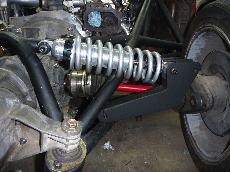
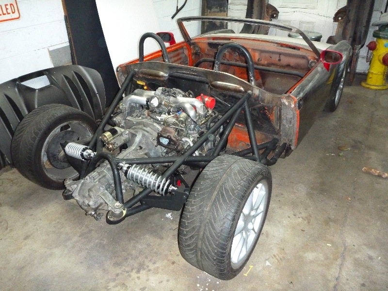
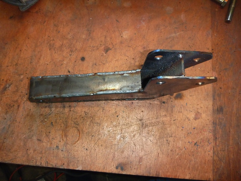 Today I built the suspension arms, I welded all of the seams from the inside, then welded and finished all of the seams on the outside. Now I have one bead of weld for structure and one for looks. I have a feeling I overbuilt the crap out of these but I would rather not risk it with suspension components. Even with the beefy arms this new suspension system weighs about a pound less per side than stock with a super low and inboard center of gravity. I shot the arms with a coat of primer and will mock things up in the morning. 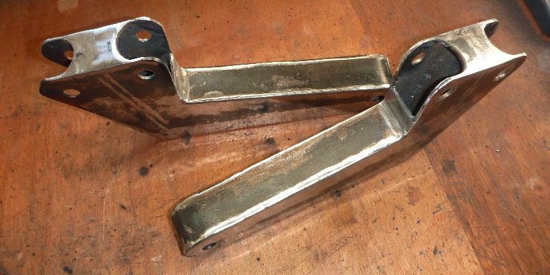 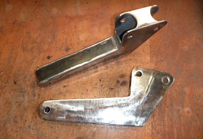 |
| Hontec |
 Nov 24 2010, 01:47 AM Nov 24 2010, 01:47 AM
Post
#651
|
|
I see things.....   Group: Members Posts: 261 Joined: 23-September 10 From: Netherlands Member No.: 12,210 Region Association: Europe |
Lookin' good (IMG:style_emoticons/default/beerchug.gif) Can't wait for the mockup....
|
| plymouth37 |
 Nov 24 2010, 09:56 AM Nov 24 2010, 09:56 AM
Post
#652
|
|
Senior Member    Group: Members Posts: 1,825 Joined: 24-May 05 From: Snoqualmie, WA Member No.: 4,138 Region Association: Pacific Northwest 
|
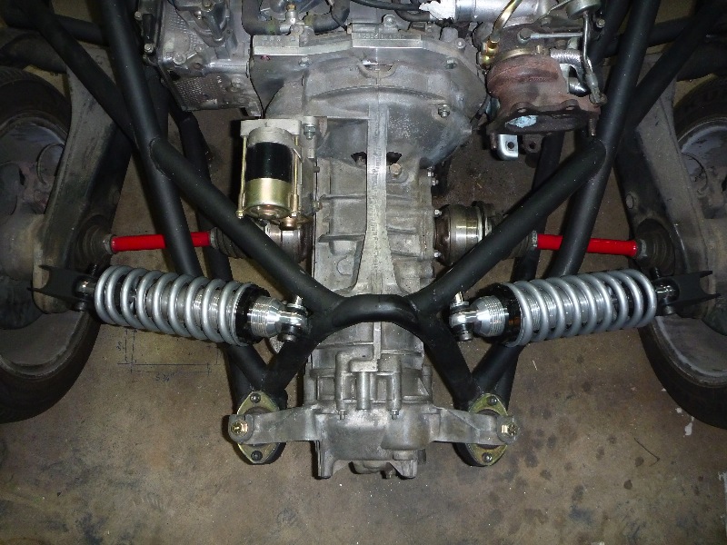
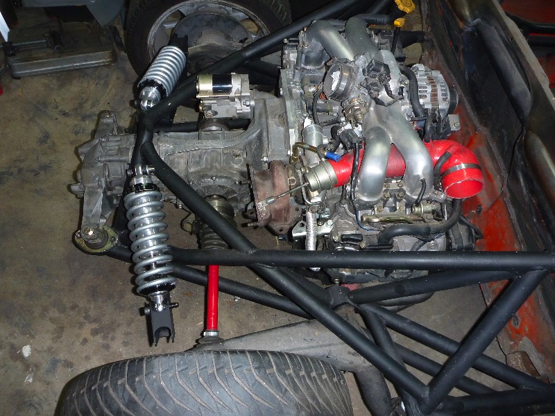
I did a loose mockup this morning, everything is just held on with zipties but you can get a pretty good idea of how this is supposed to work. I ran it through its entire range of movement and it looks like I am free of interference and binding so the next step is building mounts for everything then connecting this assembly to the trailing arm.
  |
| plymouth37 |
 Nov 24 2010, 09:56 AM Nov 24 2010, 09:56 AM
Post
#653
|
|
Senior Member    Group: Members Posts: 1,825 Joined: 24-May 05 From: Snoqualmie, WA Member No.: 4,138 Region Association: Pacific Northwest 
|
  |
| Ferg |
 Nov 24 2010, 10:14 AM Nov 24 2010, 10:14 AM
Post
#654
|
|
914 Guru      Group: Members Posts: 5,948 Joined: 8-January 03 From: Boulder CO Member No.: 116 Region Association: None 
|
(IMG:style_emoticons/default/pray.gif) Looking Good!
Hey you going to the Rod show in Denver Friday? Ferg |
| plymouth37 |
 Nov 24 2010, 10:36 AM Nov 24 2010, 10:36 AM
Post
#655
|
|
Senior Member    Group: Members Posts: 1,825 Joined: 24-May 05 From: Snoqualmie, WA Member No.: 4,138 Region Association: Pacific Northwest 
|
I am going to be in Wyoming until Sunday night so it looks like I will miss it, too bad, looks like it will be a good show!
|
| Hontec |
 Nov 24 2010, 11:01 AM Nov 24 2010, 11:01 AM
Post
#656
|
|
I see things.....   Group: Members Posts: 261 Joined: 23-September 10 From: Netherlands Member No.: 12,210 Region Association: Europe |
Nice work, can't wait to see the rest of the construction!
|
| plymouth37 |
 Nov 24 2010, 06:10 PM Nov 24 2010, 06:10 PM
Post
#657
|
|
Senior Member    Group: Members Posts: 1,825 Joined: 24-May 05 From: Snoqualmie, WA Member No.: 4,138 Region Association: Pacific Northwest 
|
One suggestion though. You might want to look into adding a bearing at the bellcrank's pivot point. While the car weights and hence suspension forces are radically different, we found the stiction to be pretty [unacceptably] high on our FSAE car with only a bushing. I think I will go with a bearing rather than the bushing I was planning on using. I just drilled a 1/2 hole at the pivot point for now to get the arm mounts placed, what type of bearings did you guys use on the FSAE car and where did you source them? |
| trojanhorsepower |
 Nov 24 2010, 06:16 PM Nov 24 2010, 06:16 PM
Post
#658
|
|
Senior Member    Group: Members Posts: 867 Joined: 21-September 03 From: Marion, NC Member No.: 1,179 Region Association: None |
OK I have a stupid question that I have wanted to ask you for a long time. Why does your car stay so shiny?? Did you clear coat it? I love this build and am just wondering since every thing I touch turns immediately to rust. Would you consider leaving it shiny with grinder marks.... I think it looks cool.
Eagerly awaiting more pictures -Pete |
| plymouth37 |
 Nov 24 2010, 10:14 PM Nov 24 2010, 10:14 PM
Post
#659
|
|
Senior Member    Group: Members Posts: 1,825 Joined: 24-May 05 From: Snoqualmie, WA Member No.: 4,138 Region Association: Pacific Northwest 
|
OK I have a stupid question that I have wanted to ask you for a long time. Why does your car stay so shiny?? Did you clear coat it? I love this build and am just wondering since every thing I touch turns immediately to rust. Would you consider leaving it shiny with grinder marks.... I think it looks cool. Eagerly awaiting more pictures -Pete The main factor is the fact that I live in Colorado and we have almost no humidity, any bare steel takes a good long time to gather even a dusting of surface rust. As far as the body goes I shot it with a layer of clear coat about 4 years ago and it has kept the rust at bay pretty well over the years. I did run the car for a couple years with just the clear coat, works pretty well when you can't afford a fancy paint job! 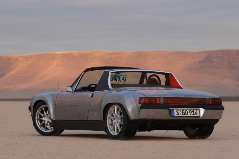 |
| McMark |
 Nov 24 2010, 11:30 PM Nov 24 2010, 11:30 PM
Post
#660
|
|
914 Freak!                Group: Retired Admin Posts: 20,179 Joined: 13-March 03 From: Grand Rapids, MI Member No.: 419 Region Association: None |
I'm not sure I understand. Seems like that orientation will achieve very little shock compression, because the pivot point is not between the trailing arm attachment and the shock attachment.
What am I missing? Attached image(s) 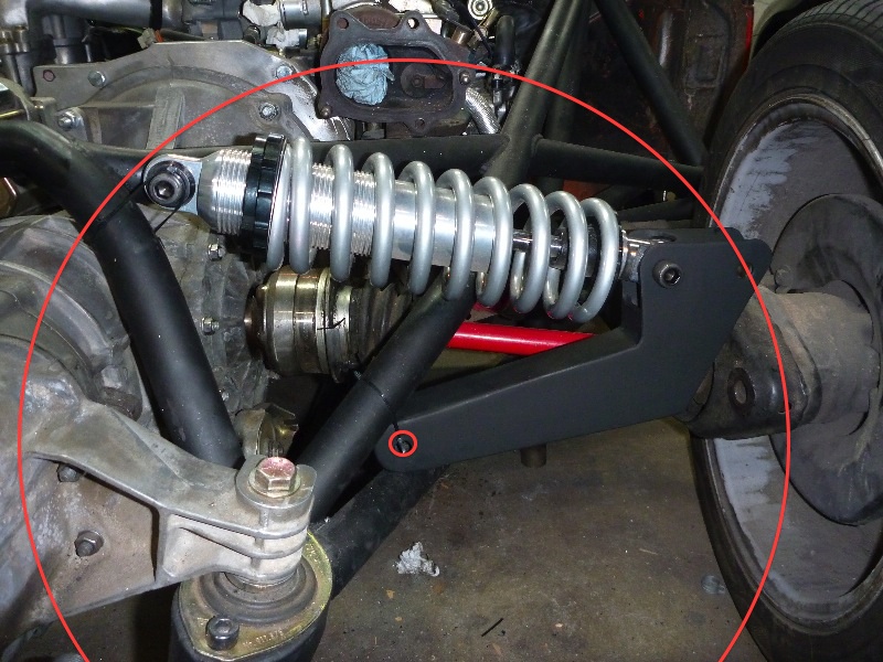
|
  |
1 User(s) are reading this topic (1 Guests and 0 Anonymous Users)
0 Members:

|
Lo-Fi Version | Time is now: 20th April 2025 - 05:38 AM |
Invision Power Board
v9.1.4 © 2025 IPS, Inc.


