|
|

|
Porsche, and the Porsche crest are registered trademarks of Dr. Ing. h.c. F. Porsche AG.
This site is not affiliated with Porsche in any way. Its only purpose is to provide an online forum for car enthusiasts. All other trademarks are property of their respective owners. |
|
|
  |
| Hontec |
 Jan 16 2011, 03:23 AM Jan 16 2011, 03:23 AM
Post
#761
|
|
I see things.....   Group: Members Posts: 261 Joined: 23-September 10 From: Netherlands Member No.: 12,210 Region Association: Europe |
Dana,
how much room is there physically between your suspension pickup and the subaru cam covers? I'm also using your method of hollow tube over the pivot point on the trailing arm, but I'm thinking of moving them out to create a wider track at the rear and at the same time give me more room for whatever engine in the future.. Thanks Randall |
| plymouth37 |
 Jan 16 2011, 11:51 AM Jan 16 2011, 11:51 AM
Post
#762
|
|
Senior Member    Group: Members Posts: 1,825 Joined: 24-May 05 From: Snoqualmie, WA Member No.: 4,138 Region Association: Pacific Northwest 
|
Dana, how much room is there physically between your suspension pickup and the subaru cam covers? I'm also using your method of hollow tube over the pivot point on the trailing arm, but I'm thinking of moving them out to create a wider track at the rear and at the same time give me more room for whatever engine in the future.. Thanks Randall There is about an 3/4" of clearance between them, it is pretty tight. You are a lot better equipped to create totally custom suspension points than I am, I think it would be a good idea to explore. I did move my trailing arm mounts up by 2" so the suspension arms would sit level at the car's new lowered height, which would also be something to think about as far as positioning goes. With your skill level though you should just go with double A-arms on all 4 corners and really make us all look bad (IMG:style_emoticons/default/biggrin.gif) |
| Hontec |
 Jan 16 2011, 04:13 PM Jan 16 2011, 04:13 PM
Post
#763
|
|
I see things.....   Group: Members Posts: 261 Joined: 23-September 10 From: Netherlands Member No.: 12,210 Region Association: Europe |
Dana, how much room is there physically between your suspension pickup and the subaru cam covers? I'm also using your method of hollow tube over the pivot point on the trailing arm, but I'm thinking of moving them out to create a wider track at the rear and at the same time give me more room for whatever engine in the future.. Thanks Randall There is about an 3/4" of clearance between them, it is pretty tight. You are a lot better equipped to create totally custom suspension points than I am, I think it would be a good idea to explore. I did move my trailing arm mounts up by 2" so the suspension arms would sit level at the car's new lowered height, which would also be something to think about as far as positioning goes. With your skill level though you should just go with double A-arms on all 4 corners and really make us all look bad (IMG:style_emoticons/default/biggrin.gif) I'm also in discussion about that, I can change certain chassis groups but there is a limit, suspension, engine and chassis. If I change 2/3 . I will have to get a new title, something I'm trying to avoid to all extent. Raising the pickup points is something I will surely do, even maybe move them out some.. |
| plymouth37 |
 Jan 16 2011, 08:58 PM Jan 16 2011, 08:58 PM
Post
#764
|
|
Senior Member    Group: Members Posts: 1,825 Joined: 24-May 05 From: Snoqualmie, WA Member No.: 4,138 Region Association: Pacific Northwest 
|
No real work done today, I am pretty much done with the rear half barring a few bits I need to buy. For now I am going to set it aside to start cleaning up the rear of the tub in preparation for its amputation. I am going to rebuild the area where the back half was cut off so it looks a little more "finished".
Here are a couple pics of the car separated. I timed myself and it only takes 20 minutes working leisurely to split the car in half. 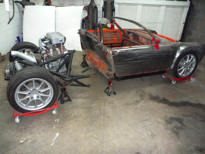 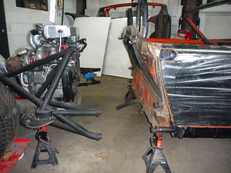 |
| smontanaro |
 Jan 17 2011, 06:15 AM Jan 17 2011, 06:15 AM
Post
#765
|
|
Senior Member    Group: Members Posts: 1,190 Joined: 3-June 05 From: Evanston, IL Member No.: 4,197 Region Association: Upper MidWest |
After you take it apart and put it back together will it need to be realigned? I can't tell from the pictures how the back end connects to the tub.
|
| URY914 |
 Jan 17 2011, 07:26 AM Jan 17 2011, 07:26 AM
Post
#766
|
|
I built the lightest 914 in the history of mankind.                                                                                                     Group: Members Posts: 126,119 Joined: 3-February 03 From: Jacksonville, FL Member No.: 222 Region Association: None |
Can we see a close up of the connection details. How the rear tubes connect to the mid section. Thanks
|
| plymouth37 |
 Jan 17 2011, 10:26 AM Jan 17 2011, 10:26 AM
Post
#767
|
|
Senior Member    Group: Members Posts: 1,825 Joined: 24-May 05 From: Snoqualmie, WA Member No.: 4,138 Region Association: Pacific Northwest 
|
This is what the connectors look like, they fit together like puzzle pieces and have 2 bolts coming in from opposite sides to hold them together. The other end slips into the tubing, I welded the seam as well as a few plug welds to attach them.
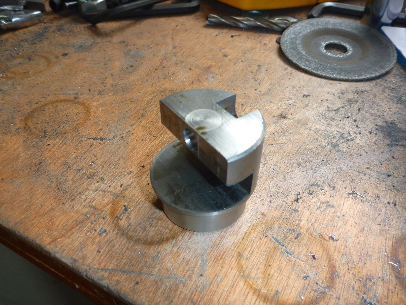 Here they are installed on the car, you can see the smaller diameter end that the tubing slips over as well as the seam that divides the 2 pieces. In the top of the lower connector you can see the ends of the bolts that hold the pieces together. 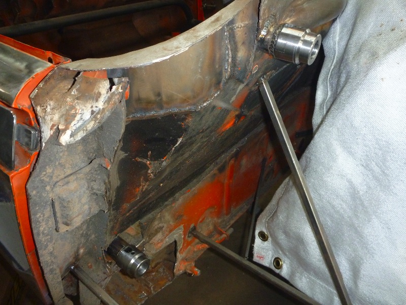 |
| plymouth37 |
 Jan 17 2011, 10:29 AM Jan 17 2011, 10:29 AM
Post
#768
|
|
Senior Member    Group: Members Posts: 1,825 Joined: 24-May 05 From: Snoqualmie, WA Member No.: 4,138 Region Association: Pacific Northwest 
|
There are 6 connection points like this that attach the 2 halves, making a total of 12 bolts holding everything together. The connectors are circled in red and linked to their partner in yellow.
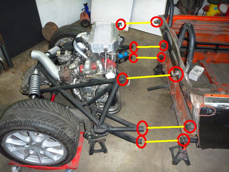 I don't think everything will need to be aligned every time the car is split, the suspension is bolted firmly to the rear half. I would think that even if the cage were to move a little when it is unbolted it will regain it's proper alignment once it is bolted back to the car. |
| r_towle |
 Jan 17 2011, 10:41 AM Jan 17 2011, 10:41 AM
Post
#769
|
|
Custom Member                Group: Members Posts: 24,705 Joined: 9-January 03 From: Taxachusetts Member No.: 124 Region Association: North East States 
|
As always, very slick.
I really like the removable rear just from a servicing standpoint. It will take up less space in the shop also....lol Rich |
| RJMII |
 Jan 17 2011, 10:51 AM Jan 17 2011, 10:51 AM
Post
#770
|
|
Jim McIntosh     Group: Members Posts: 3,125 Joined: 11-September 07 From: Sandy, Utah Member No.: 8,112 Region Association: None |
Where do you get those connectors?
|
| BKLA |
 Jan 17 2011, 10:58 AM Jan 17 2011, 10:58 AM
Post
#771
|
|
Really old member    Group: Members Posts: 1,253 Joined: 14-August 05 From: OR Member No.: 4,590 Region Association: Pacific Northwest 
|
I'm still of the opinion that you should market this set up with a roll cage and front clip. Three parts easily shipped, put together with either a donor teener, a 550 or 904 kit. Even a sheridan body kit. Just a rear half and roll cage kit would be cool!
Seems like you've designed it so that it fits a number of engines. I'd be first in line for one! |
| plymouth37 |
 Jan 17 2011, 11:12 AM Jan 17 2011, 11:12 AM
Post
#772
|
|
Senior Member    Group: Members Posts: 1,825 Joined: 24-May 05 From: Snoqualmie, WA Member No.: 4,138 Region Association: Pacific Northwest 
|
Where do you get those connectors? You can find them at a lot of off road supply places, I got mine from Ballistic Fabrication, search "clamp" on their site to find them. |
| plymouth37 |
 Jan 17 2011, 11:19 AM Jan 17 2011, 11:19 AM
Post
#773
|
|
Senior Member    Group: Members Posts: 1,825 Joined: 24-May 05 From: Snoqualmie, WA Member No.: 4,138 Region Association: Pacific Northwest 
|
I'm still of the opinion that you should market this set up with a roll cage and front clip. Three parts easily shipped, put together with either a donor teener, a 550 or 904 kit. Even a sheridan body kit. Just a rear half and roll cage kit would be cool! Seems like you've designed it so that it fits a number of engines. I'd be first in line for one! That has definitely crossed my mind, if I had a celette bench and twice as much free time I could totally do it. I am making the back half fairly independent, you could just bolt it to the front half of anything that had matching connection points, hook up a fuel line and have a self sufficient rear suspension and drive train. 350hp 3 wheelers could be fun, how about a home built Atom? (IMG:style_emoticons/default/biggrin.gif) |
| McMark |
 Jan 17 2011, 01:32 PM Jan 17 2011, 01:32 PM
Post
#774
|
|
914 Freak!                Group: Retired Admin Posts: 20,179 Joined: 13-March 03 From: Grand Rapids, MI Member No.: 419 Region Association: None |
You need a bracket to bolt on to each half so they become self supporting. (IMG:style_emoticons/default/wink.gif) That way you can easily move each part around when separated.
I just trying to slow down your progress. (IMG:style_emoticons/default/happy11.gif) Oh, and I can see your fuel pump now. Take a nice picture of that and go back and edit your earlier post to bring it up to date. |
| plymouth37 |
 Jan 17 2011, 01:36 PM Jan 17 2011, 01:36 PM
Post
#775
|
|
Senior Member    Group: Members Posts: 1,825 Joined: 24-May 05 From: Snoqualmie, WA Member No.: 4,138 Region Association: Pacific Northwest 
|
I have 4 casters that would be perfect to make each piece rollable, now if I can just get my homework done I could drag out the welder and get back to work!
|
| BKLA |
 Jan 17 2011, 01:40 PM Jan 17 2011, 01:40 PM
Post
#776
|
|
Really old member    Group: Members Posts: 1,253 Joined: 14-August 05 From: OR Member No.: 4,590 Region Association: Pacific Northwest 
|
.... Seems like you've designed it so that it fits a number of engines. .... how about a home built Atom? (IMG:style_emoticons/default/biggrin.gif) And there you go! When's the first one available? (IMG:style_emoticons/default/wink.gif) |
| plymouth37 |
 Jan 21 2011, 05:53 PM Jan 21 2011, 05:53 PM
Post
#777
|
|
Senior Member    Group: Members Posts: 1,825 Joined: 24-May 05 From: Snoqualmie, WA Member No.: 4,138 Region Association: Pacific Northwest 
|
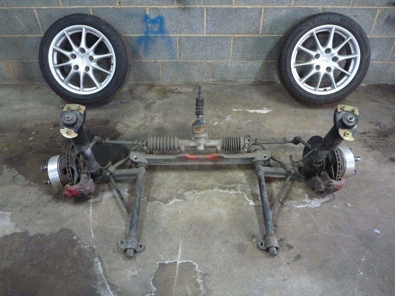
I pulled the front suspension today, I am running a full Carrera suspension including the aluminum cross member and underbody sway bar.
 I also finished plumbing the turbo hoses. 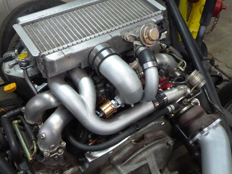 |
| plymouth37 |
 Jan 21 2011, 06:00 PM Jan 21 2011, 06:00 PM
Post
#778
|
|
Senior Member    Group: Members Posts: 1,825 Joined: 24-May 05 From: Snoqualmie, WA Member No.: 4,138 Region Association: Pacific Northwest 
|
Now that the suspension has been removed I am pretty much left with a bare tub.
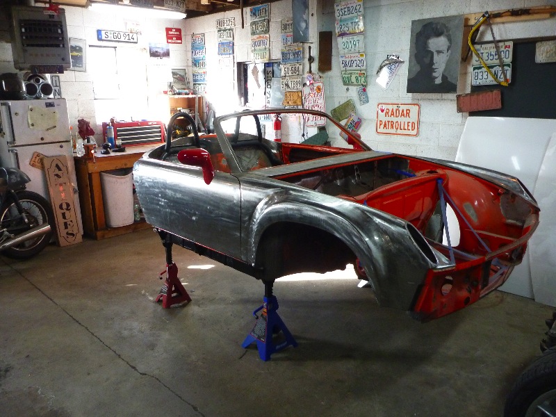 I also started cleaning up the fire wall, I have a lot of metal work to do back here over the coming months. 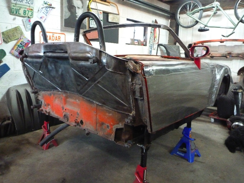 |
| fat73 |
 Jan 25 2011, 09:29 AM Jan 25 2011, 09:29 AM
Post
#779
|
|
W9R1   Group: Members Posts: 244 Joined: 7-May 05 From: tampa,fl Member No.: 4,043 Region Association: South East States |
Now that the suspension has been removed I am pretty much left with a bare tub.  I also started cleaning up the fire wall, I have a lot of metal work to do back here over the coming months.  Dana...some additional inspiration (like you need it). http://www.gizmag.com/lamborghini-introduc...tm_medium=email Ed |
| plymouth37 |
 Jan 25 2011, 11:10 AM Jan 25 2011, 11:10 AM
Post
#780
|
|
Senior Member    Group: Members Posts: 1,825 Joined: 24-May 05 From: Snoqualmie, WA Member No.: 4,138 Region Association: Pacific Northwest 
|
HAHA, Just saw that too, glad to see Lamborghini is thinking along the same lines as I am for the new LP-700 (IMG:style_emoticons/default/biggrin.gif)
I am pretty envious of those double A-arms though! 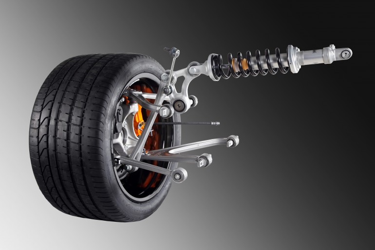 |
  |
2 User(s) are reading this topic (2 Guests and 0 Anonymous Users)
0 Members:

|
Lo-Fi Version | Time is now: 20th April 2025 - 11:19 AM |
Invision Power Board
v9.1.4 © 2025 IPS, Inc.


