|
|

|
Porsche, and the Porsche crest are registered trademarks of Dr. Ing. h.c. F. Porsche AG.
This site is not affiliated with Porsche in any way. Its only purpose is to provide an online forum for car enthusiasts. All other trademarks are property of their respective owners. |
|
|
  |
| RiqueMar |
 Dec 29 2020, 11:33 AM Dec 29 2020, 11:33 AM
Post
#921
|
|
Enrique Allen Mar     Group: Members Posts: 2,210 Joined: 28-August 08 From: San Diego, CA Member No.: 9,478 Region Association: Southern California 
|
Happy to say I'm 'wrapping up' the front trunk harness. Decided to move away from the 'stock look' of wrapped tape, and go with something more modern. This is also safer for the 2x new +12v lines I added below the tank for items in the front trunk.
Unfortunately, I had to crack-open the relay box I installed previously. I decided to add a horn relay for a more euro-sounding horn now located in the driver-side wheel well and a new relay for the foglight. So, now that its complete, the front relay box now powers the fuel-pump, oil-cooler fans (with a dash-mounted switch for manual over-ride) air-horn, fog-lights, and one 'open' relay for something in the future. I need to read more into the whole 'headlight relay' thing as it relates to the stock 914/6 column, but I think that I can run that near the stock fuse-board to be both easier and cleaner. Speaking of the 914/6 column and controls, this is my current focus after adding the new equipment and wrapping the front portion of the harness with safety-sheathing. I've started on a conversion table for converting the 75' harness to the 914/6 connector, and will post once complete. 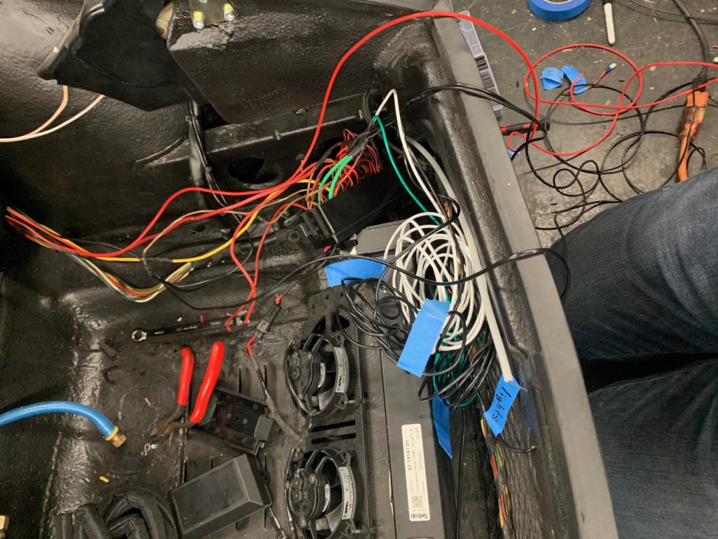 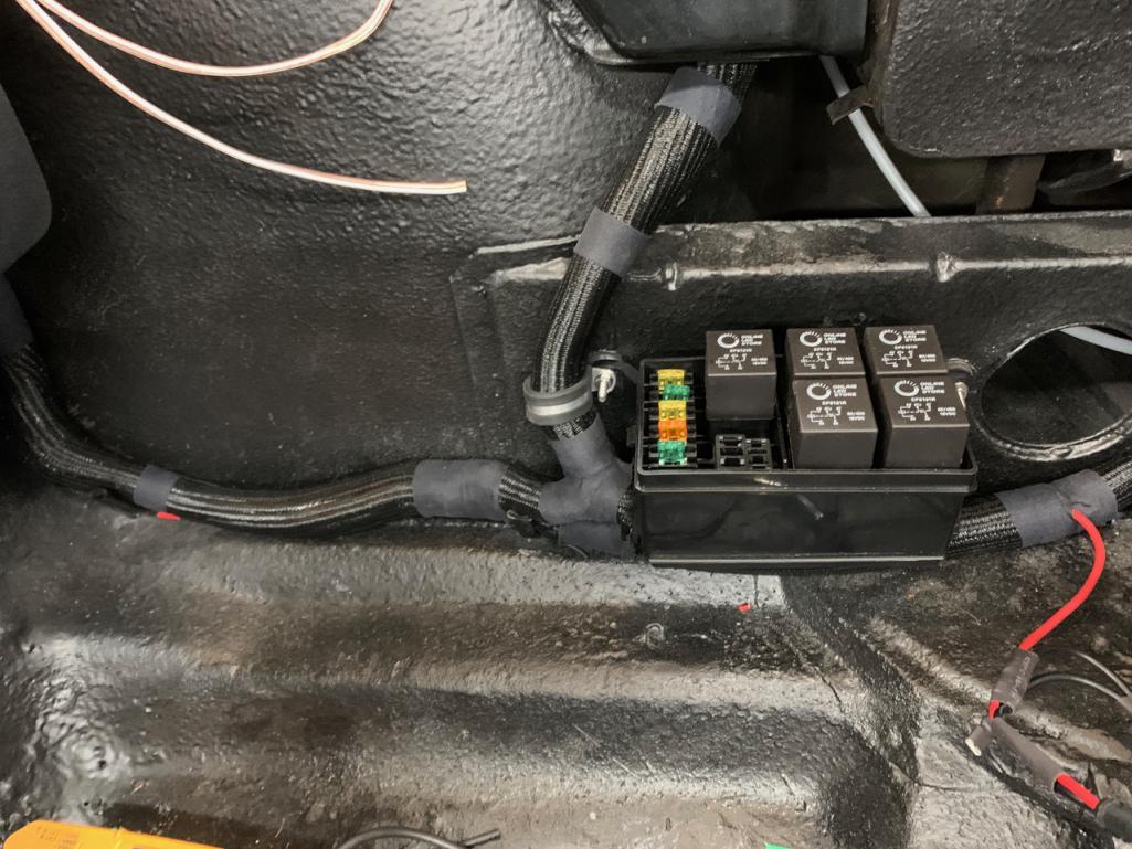 |
| Cairo94507 |
 Dec 29 2020, 12:01 PM Dec 29 2020, 12:01 PM
Post
#922
|
|
Michael           Group: Members Posts: 10,285 Joined: 1-November 08 From: Auburn, CA Member No.: 9,712 Region Association: Northern California 
|
Hi Enrique, @RiqueMar - Car is looking very nice. You have to be getting close to being able to drive that, right? (IMG:style_emoticons/default/beerchug.gif)
|
| RiqueMar |
 Dec 29 2020, 01:27 PM Dec 29 2020, 01:27 PM
Post
#923
|
|
Enrique Allen Mar     Group: Members Posts: 2,210 Joined: 28-August 08 From: San Diego, CA Member No.: 9,478 Region Association: Southern California 
|
@Cairo94507 - So close! Using my 2 weeks of vacation this year to work on the car. Front trunk wrapped up, same with the rear, and I'm pretty sure I have the DME relay setup working properly.
(IMG:style_emoticons/default/icon_bump.gif) Right now, main focus is figuring out the conversion wiring I mentioned in my last post. I've snipped the original black 75' connector, and have temporarily installed male/female connectors to troubleshoot. If anyone can point me in the right direction of the column/wiper controls, I would be very grateful. (IMG:style_emoticons/default/bye1.gif) 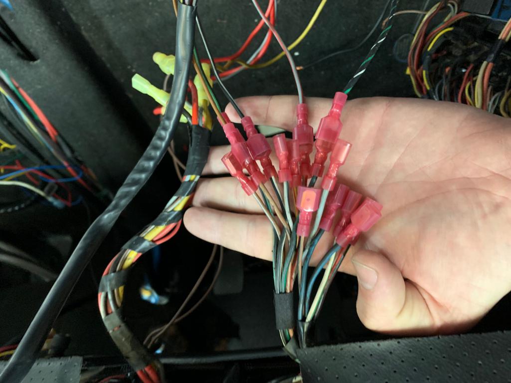 |
| RiqueMar |
 Dec 31 2020, 01:05 AM Dec 31 2020, 01:05 AM
Post
#924
|
|
Enrique Allen Mar     Group: Members Posts: 2,210 Joined: 28-August 08 From: San Diego, CA Member No.: 9,478 Region Association: Southern California 
|
I ask again, "How do you eat an elephant? One bite at a time"
Moving forward on the relay-box up front, and working with the dash recently, developed a few electrical gremlins. Nothing too big, but it certainly has made the 914-6 column and wiring take a bit longer than expected. Right now, each of the turn signal and parking lights on the 75' harness and grounding-out, and I don't think that problem was there before, more on that as it develops. I'm happy to say I took this opportunity to test out both my front-mounted fog-light relay (I retained the original relay on the fuse-board as well) and also installed the LEDs from 914rubber.com. VERY BRIGHT, plug and play, love it. (more on that and fog lights in the following posts.... 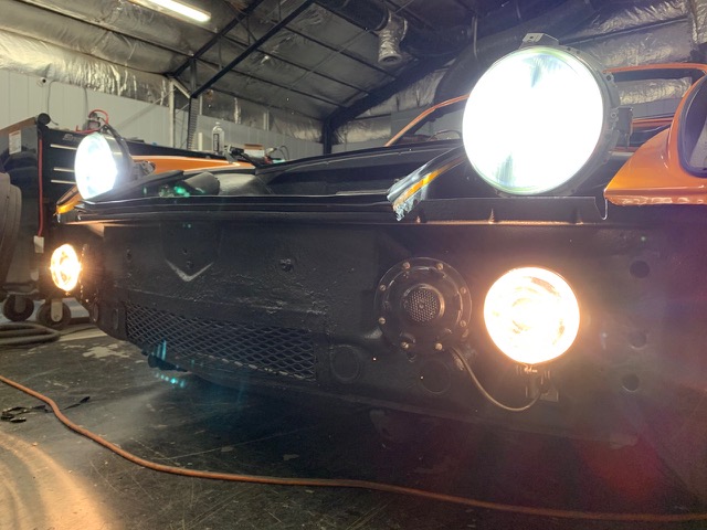 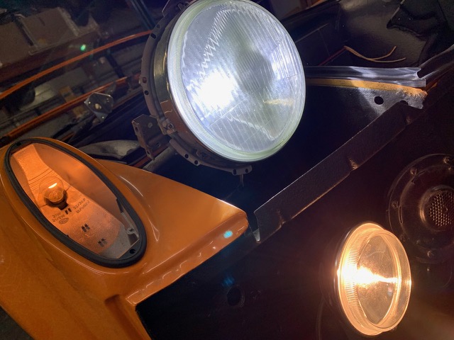 |
| RiqueMar |
 Dec 31 2020, 01:20 AM Dec 31 2020, 01:20 AM
Post
#925
|
|
Enrique Allen Mar     Group: Members Posts: 2,210 Joined: 28-August 08 From: San Diego, CA Member No.: 9,478 Region Association: Southern California 
|
A bit about headlights concerning 914-6 column controls
NOTE: My car is a 1970 914-4, with a 1975 modified wiring harness using various 914-6 / 964 parts For those readers following this thread using an actual 914-6 on a 914-4 harness, see page 40 of this build-thread. Essentially, one will need to eliminate the stock 914/4 headlight relay (attached in this post - first photo circled in neon green), which can become troublesome as then the 914-6 switch (possibly the same for 911 conversions) takes the entire load of the hi-lo beams and can lead to the contacts burning out. This would result in the need to install a different relay(s) OR simply converting to LEDs. My take? Ditch the stock relay, pay the $120 to 914rubber, and call it a night. Furthermore, make sure that the contacts on the 914-6 turn signal / light switch are bent and not protruding too much (see the second photo, also highlighted in green). The bracket / cradle that allows this switch to attach to the steering column only allows a bit of clearance. In my case, my high-beam was grounding out against the column, and I nearly burnt-out my switch, 12-pin connector, and some of my wiring harness. Learn from my mistake! Specifically for the headlights, the wire-conversion is as follows...  Attached thumbnail(s) 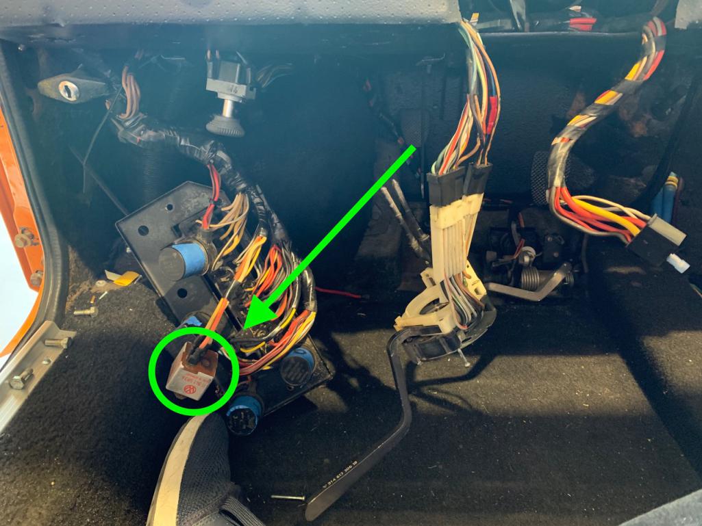 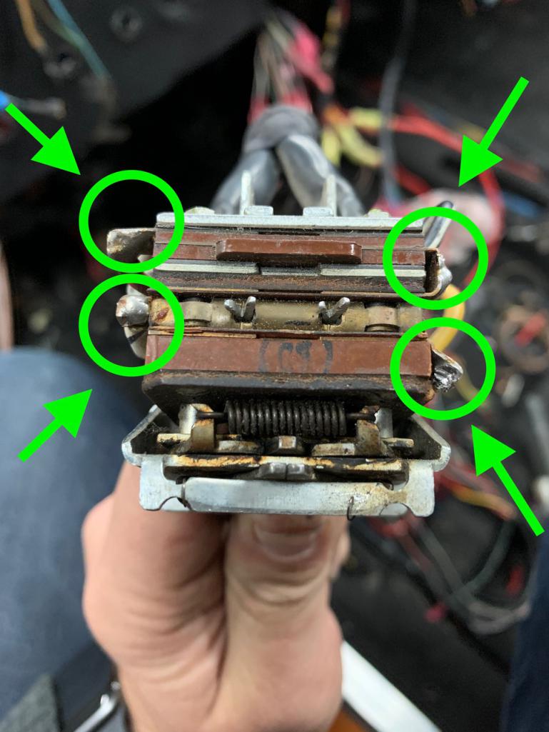
|
| RiqueMar |
 Jan 4 2021, 01:42 PM Jan 4 2021, 01:42 PM
Post
#926
|
|
Enrique Allen Mar     Group: Members Posts: 2,210 Joined: 28-August 08 From: San Diego, CA Member No.: 9,478 Region Association: Southern California 
|
Another couple of days, and more progress!
I'm happy to say, I now have all the stock components (Turn signals, High/Lo-beams, Hazards, Blower, Ignition, etc.) working with the stock controls and 914-6 controls, and I've started soldering the original harness and new components together. Progress photos below, diagrams to come.  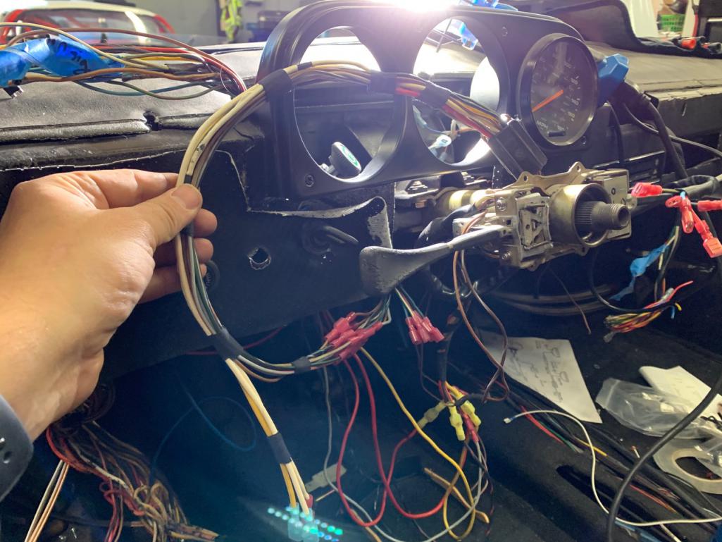 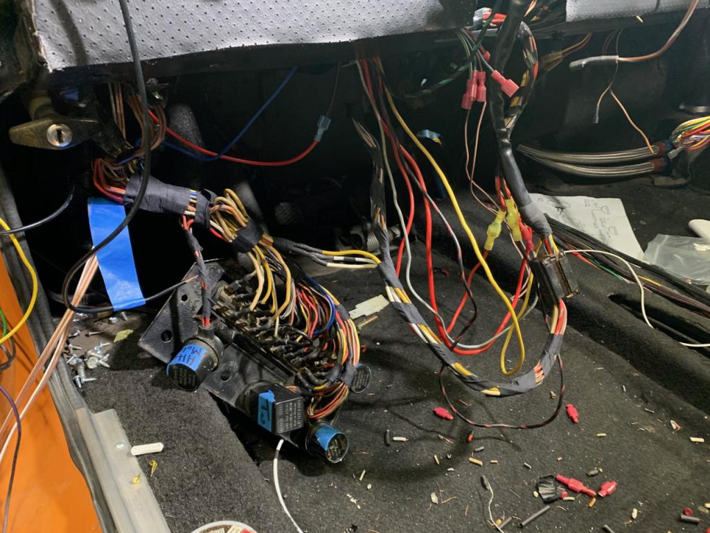 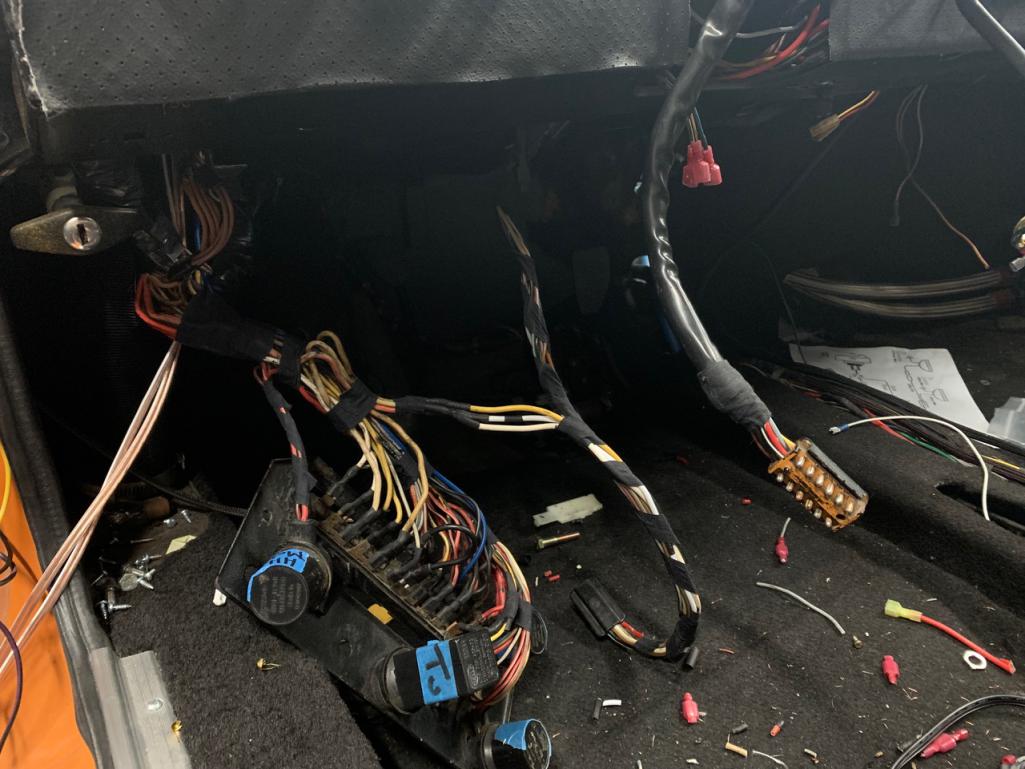 |
| RiqueMar |
 Jan 4 2021, 10:10 PM Jan 4 2021, 10:10 PM
Post
#927
|
|
Enrique Allen Mar     Group: Members Posts: 2,210 Joined: 28-August 08 From: San Diego, CA Member No.: 9,478 Region Association: Southern California 
|
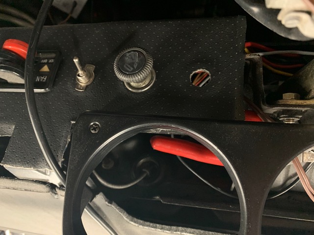
The relay box up front is now 100% active. Turning on the ignition powers the fuel-pump relay, need to decide if its through the DME or a new relay (more on that later) as well as power to the oil-cooler fans, controlled by the thermo-switch. Additionally, I added a dash-mounted switch in case the thermo-switch fails, diagram and a few reference photos below.
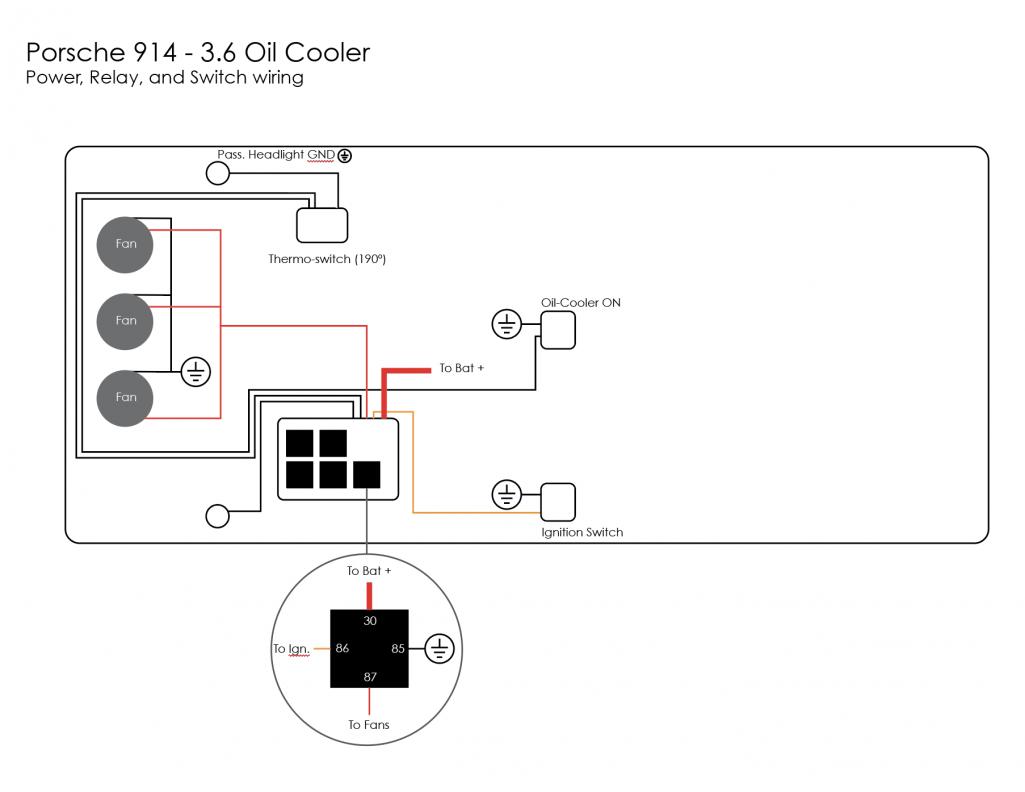 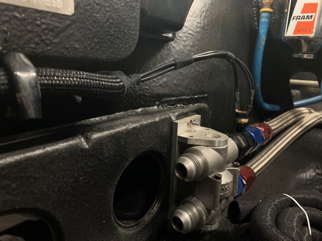  |
| RiqueMar |
 Jan 5 2021, 12:07 AM Jan 5 2021, 12:07 AM
Post
#928
|
|
Enrique Allen Mar     Group: Members Posts: 2,210 Joined: 28-August 08 From: San Diego, CA Member No.: 9,478 Region Association: Southern California 
|
Also, while digging into the dash to finish up the ignition wiring and install switches, I decided to 'isolate' the Fog-light switch and set it up so that it only functions with the key on while staying independent of the hi/lo beams.
I've browsed the site and there are no shortage of instructions on how to do this. I'm happy to say while it's pretty simple, the various threads make it a bit confusing. Below, I listed out what I did that worked excellent for making the foglight function independently ONLY when the key is in the ON position, for fear of draining the battery. NOTE: Future modification - Since the 914 has 'bucket' lights, this doesn't make sense to use these for 'flash-to-pass' during the daytime, I'm thinking that I'll wire the fog-lights to be my 'flash-to-pass', but thats a weekend project sometime in the future. 1 - Disconnect the battery 2 - Locate the Fog-light relay on the fuse board and notice the white wire with a blue-stripe (first-photo of this post) in my case, this led to pin 1 on the fuses. 3 - Cut / Connect / Solder the blue and white wire to GND. 4 - Disconnect the Black/Blue wire from the foglight switch (mine was located on the 'K' terminal.) Wrap / isolate the Blue / Black wire, it will no longer be in use. 5 - Run a lead (mine is Blue in the photos) from the 'K' terminal on the foglight switch to something that is only ON when the key is in the ON position. (I used pin 9) 6 - Reconnect the battery and test all your connections, its easy to unplug things on the fuse board when doing this (happened to me with my passenger side lights). 7 - Use this opportunity to check the connections / clean your fuse board, clean and tape your harness. (Note Not necessary to open the harness for this, I just had mine accessible). 8 - Test again before wrap up. Note: Browsing through the posts I found the attached diagram and it made everything clear to me, save for the pins on the fog-lights. In the diagram, it lists using pin 15 on the foglight switch, whereas mine was wired for 'K'.[size=2] 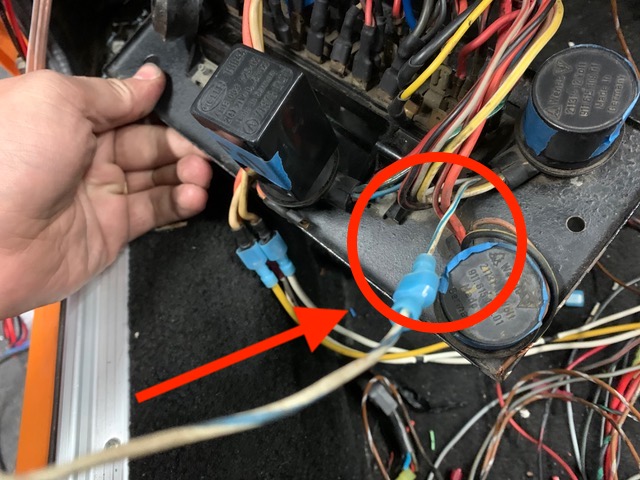 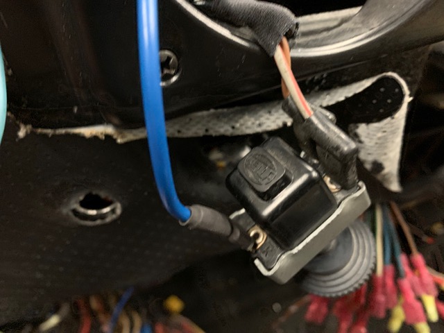 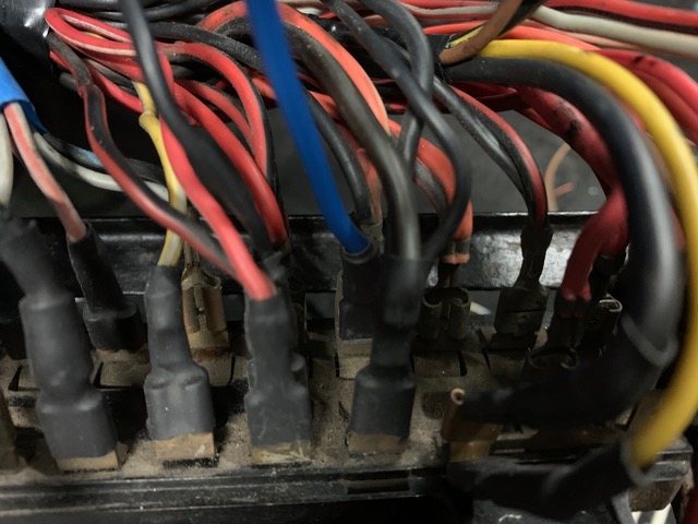 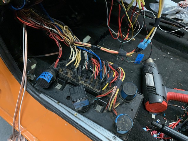 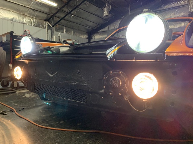 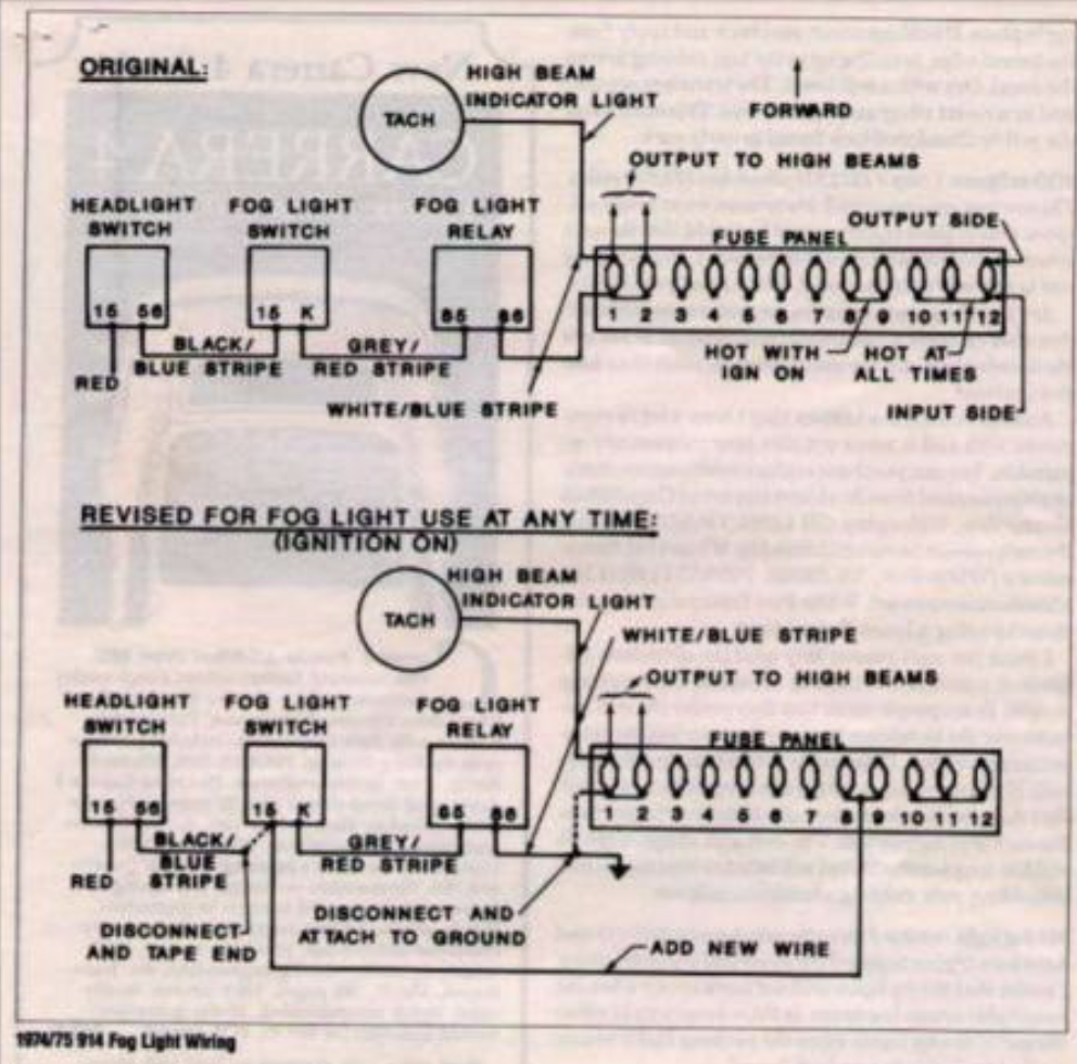 |
| ClayPerrine |
 Jan 5 2021, 08:51 AM Jan 5 2021, 08:51 AM
Post
#929
|
|
Life's been good to me so far.....                Group: Admin Posts: 16,242 Joined: 11-September 03 From: Hurst, TX. Member No.: 1,143 Region Association: NineFourteenerVille 
|
The DME relay controls both the ECU/Injectors/Ignition igniters/etc... and the Fuel Pump/O2 sensor heater. The fuel pump portion of the DME relay is turned on by a signal from the ECU. If you wire it so the fuel pump is on all the time, it will not work right.
Inserted below is an Excel spreadsheet I made to put my 964 motor in. It may help you, but it does have some specific notes in it about my car. I am also attaching the 964 engine wiring diagram, which contains the DME relay and the ECU. I hope it helps. Let me know if you need any more info. Clay 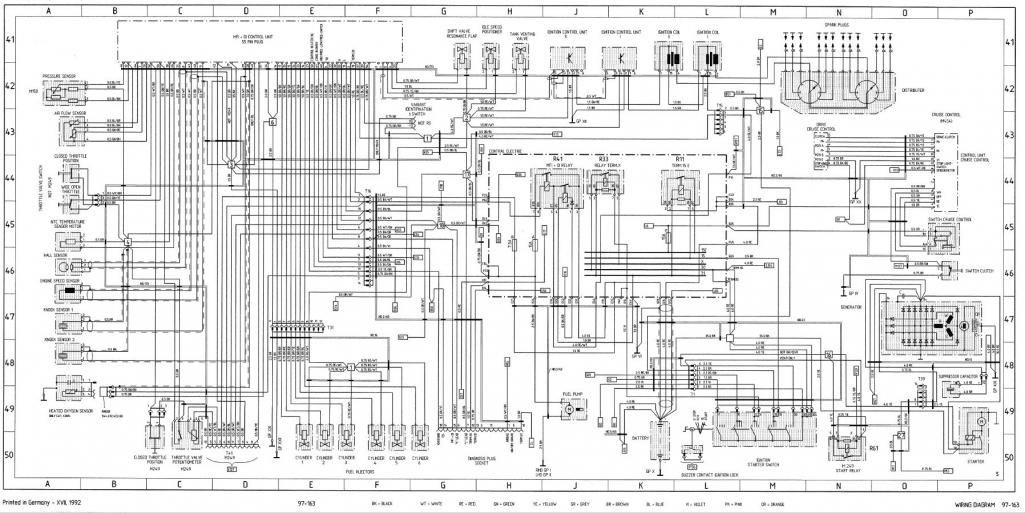 ECU Pin Wire Color Gauge 964 ECU Function Target Device and Pin number 1 White 14 Ignition Modules Signal Igniton Control Mudules 1 and 2 Pin 5 2 Brown 14 Ignition Modules Ground Igniton Control Mudules 1 and 2 Pin 3 3 Black/White 18 Fuel Pump Relay Fuel Pump Relay pin 85 4 Black/Red 18 Idle Speed Control Idle Speed Positioner pin 2 5 N/C Tank Venting Valve Tank Venting Valve pin 2 6 Red/Blue 18 Tachometer Output 914/6 Relay board Engine plug pin 2 7 Blue/Green 18 Air Flow Meter Signal Air Flow Meter Pin 2 8 White/Shield 18 Hall Sensor Signal Hall Sensor Pin 2 9 Red/Black 18 N/C 10 Brown 18 Oxygen Sensor Shield Ground Ground on Body at battery cable. 11 Green/Shield 18 Knock Sensor Number 1 Knock Sensor Number 1 Pin 2 12 Blue/Gray 18 Air Flow Meter Power Air Flow Meter Pin 3 / Pressure Sensor Pin 3 13 Blue/White 18 Diagnostic Plug Lead L OBD2 Connector Pin 15 14 Brown/Red 14 Ground Ground on Body at battery cable. 15 N/C Injector Number 3 Fuel Injector Number 3 Pin 1 16 Gray 18 Injector Number 6 Fuel Injector Number 6 Pin 1 17 Gray/Black 18 Injector Number 1 Fuel Injector Number 1 Pin 1 18 Red 16 Always on Positive ECU Power Battery via Auxuiluary Fuse Box in Engine Compartment. 19 White 16 Ground Ground on Body at battery cable. 20 N/C N/C 21 Black/ 18 Diagnostic Plug Knock Indicator OBD2 Connector Pin 11 22 Black/White 18 Check Engine Light added to bottom of Tachometer / OBD2 Plug Pin 9 23 Blue/Red 18 Resonance Plate Shift Valve Resonance Flap Pin 2 24 Brown/Yellow 16 Ground Ground on Body at battery cable. 25 Yellow/Red 18 N/C 26 Green/Red 18 Air Flow Meter Ground Air Flow Meter Pin 4 27 Black 16 N/C 28 Green/Shield 16 Oxygen Sensor Signal Oxygen Sensor Pin 1 29 Green/Shield 16 Knock Sensor Number 2 Knock Sensor Number 2 Pin 2 30 Brown 18 Shield for Knock Sensors, Hall Sensor and Knock Sensor Ground. Ground on Body at battery cable. 31 Yellow/Gray 18 Positive to Hall Sensor Hall Sensor Pin 3 32 Red/Green 18 Comsumption Gauge 33 Green/Blue 18 Injector Number 5 Fuel Injector Number 5 Pin 1 34 Gray/Red 18 Injector Number 4 Fuel Injector Number 4 Pin 1 35 Green/Blue 18 Injector Number 2 Fuel Injector Number 2 Pin 1 36 Red/Black 18 N/C 37 Red/Yellow 16 Switched Power from ECU Relay ECU Relay Pin 87 38 N/C N/C 39 N/C N/C 40 White/Black 18 AC Compressor AC Compressor Coil Power 41 Blue/Green 18 AC Cutoff sensors High Pressure/Low pressure cutoff valves for AC. 42 N/C N/C 43 N/C N/C 44 N/C Intake Air Temperature Sensor 45 Yellow 18 Engine Temperature Sensor Cylinder Head Temprature Sensor Pin 3 46 N/C Altitude Potentiometer Pressure Sensor Pin 1 47 Yellow/Red 18 Speed Reference Sensor Flywheel Sensor Pin 1 48 Brown 18 Speed Reference Shield Flywheel Sensor Pin 2 49 White/Shield 18 N/C 50 N/C Heat/AC Regulator 51 N/C N/C 52 N/C Throttle Valve Idle Signal Throttle Valve Switch Pin 1 53 White/Grey 18 Throttle Valve Full Load Signal Throttle Valve Switch Pin 3 54 White 18 Coding Plug Coding Plug in Passenger Compartment 55 Orange/White 18 Diagnostic Plug K OBD2 Connector Pins 3 and 7 |
| RiqueMar |
 Jan 11 2021, 01:15 PM Jan 11 2021, 01:15 PM
Post
#930
|
|
Enrique Allen Mar     Group: Members Posts: 2,210 Joined: 28-August 08 From: San Diego, CA Member No.: 9,478 Region Association: Southern California 
|
@ClayPerrine - Wow, completely missed this message, very helpful. For some reason, the board format throws the organization off, so I imported into a .doc and took a screenshot.
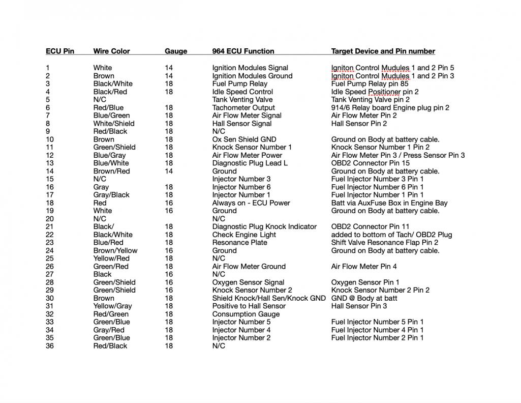 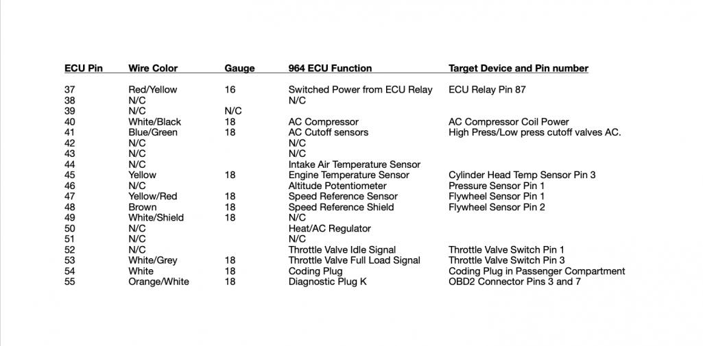 |
| RiqueMar |
 Jan 11 2021, 01:23 PM Jan 11 2021, 01:23 PM
Post
#931
|
|
Enrique Allen Mar     Group: Members Posts: 2,210 Joined: 28-August 08 From: San Diego, CA Member No.: 9,478 Region Association: Southern California 
|
Update: This is where I'm at currently. Much of the weekend was spent documenting the current state of the wiring, as it worked before (first screenshot). From my limited understanding, this works, though it's not ideal for several reasons....
- The ignition powers the DME, ECU and Fuel pump, whereas the Fuel-pump need to run off the DME. - The ECU is getting power from a standard relay, not allowing it to save 'memory'. - The Diagnostic port isn't fully functional; Not reading 'Check Engine', Engine Speed, etc. - Gauges weren't necessarily connected. I believe I've pretty much mapped everything, so now, it comes to the point where I have to create a new diagram and run off of that. Needing a break from the Computer work and sitting in the compartment, I also took this chance to clean up my connections at the fuse board, install new fuses, and clean all the contacts. I was getting a lot of false readings and gremlins, this cleared all of those. NOTE: The below screenshot of the wiring diagram is WRONG. 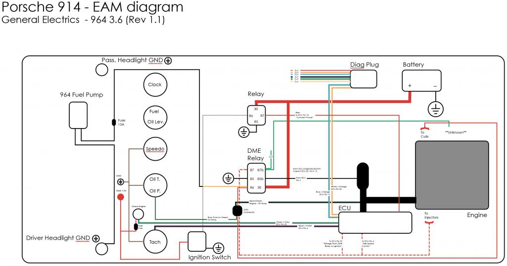 |
| RiqueMar |
 Jan 11 2021, 01:26 PM Jan 11 2021, 01:26 PM
Post
#932
|
|
Enrique Allen Mar     Group: Members Posts: 2,210 Joined: 28-August 08 From: San Diego, CA Member No.: 9,478 Region Association: Southern California 
|
Attached below, these are the changes I think I need to make....
Attached thumbnail(s) 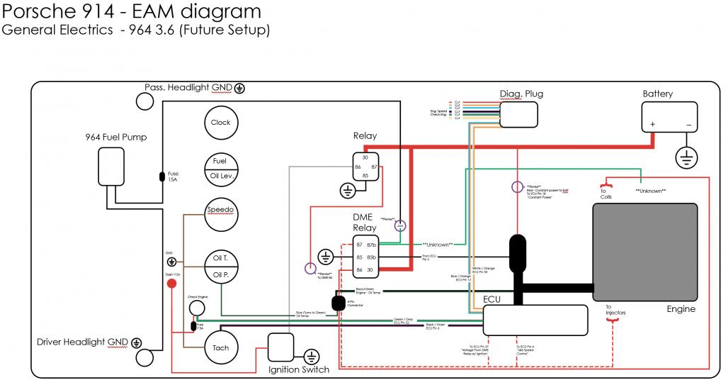
|
| RiqueMar |
 Jan 14 2021, 12:04 PM Jan 14 2021, 12:04 PM
Post
#933
|
|
Enrique Allen Mar     Group: Members Posts: 2,210 Joined: 28-August 08 From: San Diego, CA Member No.: 9,478 Region Association: Southern California 
|
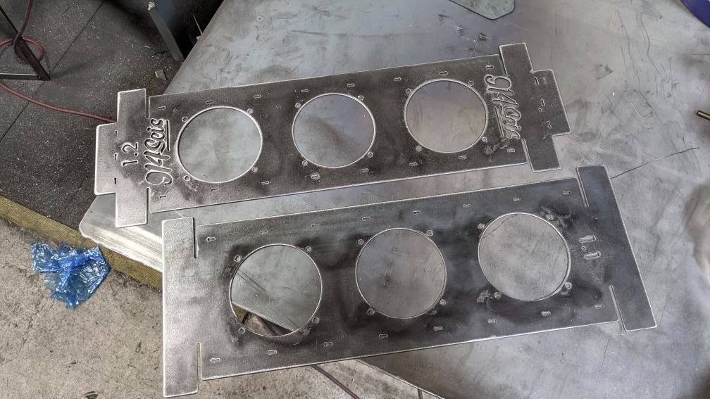
Moving along, and I'm happy to show-off first prototypes of the oil-cooler fan mount. Will be bending and testing a few different designs this weekend. (IMG:style_emoticons/default/bye1.gif)
 |
| RiqueMar |
 Jan 17 2021, 09:45 PM Jan 17 2021, 09:45 PM
Post
#934
|
|
Enrique Allen Mar     Group: Members Posts: 2,210 Joined: 28-August 08 From: San Diego, CA Member No.: 9,478 Region Association: Southern California 
|
Another weekend, and I'm marching ahead!
First order of business was to wrap up the wiring for the three primary gauges dash; Speedometer, Tachometer, Oil Temp / Oil Pressure. Center console to follow, though thats significantly easier (Fuel Level, Oil Level, Clock with Status lights). This was easy enough, given the 964 diagram. Photos and references to come. In addition to connecting up a few items that didn't really exist before, I left 3x 'extra wires' that run back to the ECU for future use. All connections work, and I only have 4 wires that I have to figure out (Speedo signal, Oil Pressure Sender, Tach +12v and Tach signal) and I was even able to run 2x new lines to differentiate between Right and Left Turn-signals. I'm not 100% familiar with the different icons from the 964, so I'm thinking to make my 'idiot light' the big 'EXCLAMATION MARK' signal found on the Oil combo gauge. Done here for now, once everything is tested, I'll probably wrap in the same manner to match the rest of the harness. (IMG:style_emoticons/default/bye1.gif) 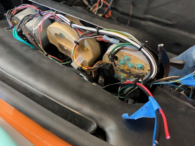 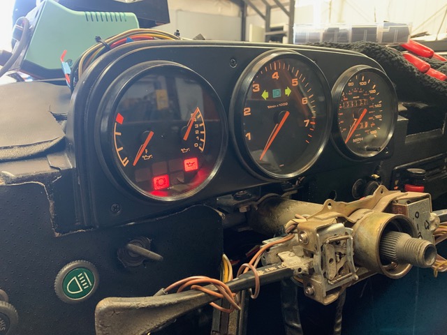 |
| RiqueMar |
 Jan 17 2021, 09:49 PM Jan 17 2021, 09:49 PM
Post
#935
|
|
Enrique Allen Mar     Group: Members Posts: 2,210 Joined: 28-August 08 From: San Diego, CA Member No.: 9,478 Region Association: Southern California 
|
Final part of the weekend was spent fitting the new Oil cooler bracket. Bent and modified the bracket after being cut, added a few screws and rubber isolators and it fits excellent!
For those members with similar projects, needed this part, feel free to contact me. I now have a design for this bracket that can incorporate up to 4-fans (IMG:style_emoticons/default/aktion035.gif) 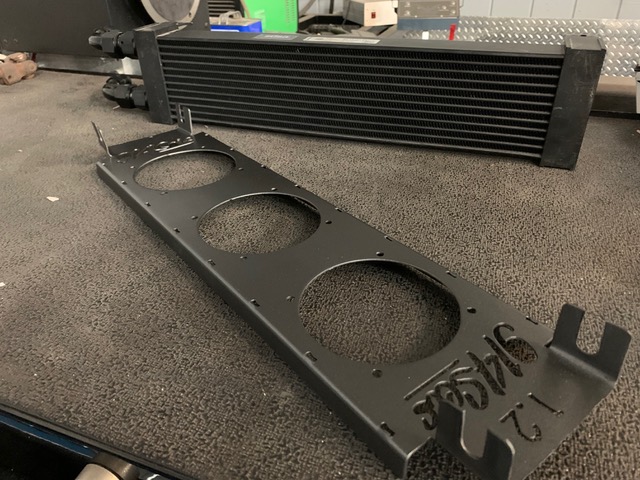 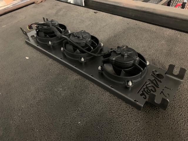 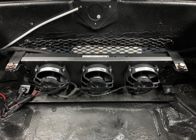 |
| euro911 |
 Jan 18 2021, 01:08 PM Jan 18 2021, 01:08 PM
Post
#936
|
|
Retired & living the dream. God help me if I wake up!      Group: Members Posts: 8,876 Joined: 2-December 06 From: So.Cal. & No.AZ (USA) Member No.: 7,300 Region Association: Southern California 
|
Looking good (IMG:style_emoticons/default/aktion035.gif)
|
| RiqueMar |
 Jan 18 2021, 02:39 PM Jan 18 2021, 02:39 PM
Post
#937
|
|
Enrique Allen Mar     Group: Members Posts: 2,210 Joined: 28-August 08 From: San Diego, CA Member No.: 9,478 Region Association: Southern California 
|
@euro911 - Gracias Señor Mark! Hey, out of curiosity, what ever happened to that 2ltr? If I remember correctly, it's been at or almost 10 years! (IMG:style_emoticons/default/bye1.gif) |
| Cairo94507 |
 Jan 18 2021, 03:01 PM Jan 18 2021, 03:01 PM
Post
#938
|
|
Michael           Group: Members Posts: 10,285 Joined: 1-November 08 From: Auburn, CA Member No.: 9,712 Region Association: Northern California 
|
@RiqueMar - Looking nice. I like the gauges. You are getting so close now. Keep up the great progress. (IMG:style_emoticons/default/beerchug.gif)
|
| euro911 |
 Jan 18 2021, 04:26 PM Jan 18 2021, 04:26 PM
Post
#939
|
|
Retired & living the dream. God help me if I wake up!      Group: Members Posts: 8,876 Joined: 2-December 06 From: So.Cal. & No.AZ (USA) Member No.: 7,300 Region Association: Southern California 
|
Looking good (IMG:style_emoticons/default/aktion035.gif) @euro911 - Gracias Señor Mark! Hey, out of curiosity, what ever happened to that 2ltr? If I remember correctly, it's been at or almost 10 years! (IMG:style_emoticons/default/bye1.gif)Here's a pic of when we installed it though ... 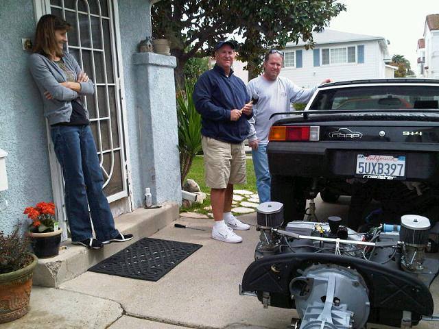 ... and later, the 2056 motor when I had the shop 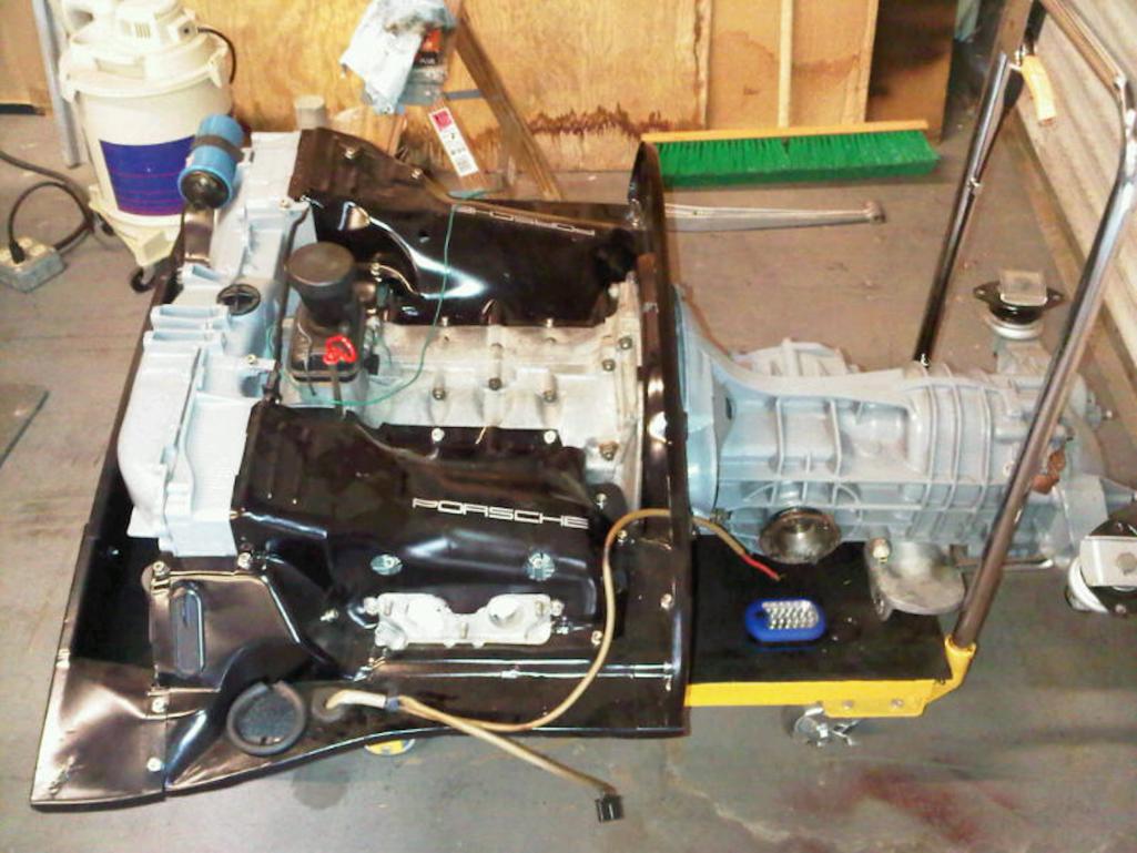 |
| RiqueMar |
 Mar 16 2021, 06:42 PM Mar 16 2021, 06:42 PM
Post
#940
|
|
Enrique Allen Mar     Group: Members Posts: 2,210 Joined: 28-August 08 From: San Diego, CA Member No.: 9,478 Region Association: Southern California 
|
Long time - no post, but I'm still on the project and plan on building back-up the momentum this week. (IMG:style_emoticons/default/piratenanner.gif) It's been a hell of a a couple of months; Lots of travel and work, some to great locations, however I'm excited to get rolling.
In addition to photos of the different travel locations, also sharing a few from my side projects; The GT Cooler bracket (Link here >GT Cooler Bracket) and just as well, I've also begun pulling molds and parts for a front and rear GT valence (see my other thread here > GT Front / Rear Valance) Enjoy, hope to update soon! (IMG:style_emoticons/default/bye1.gif) 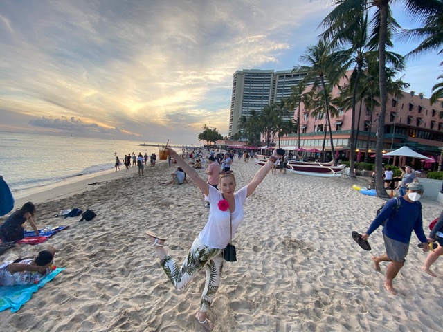 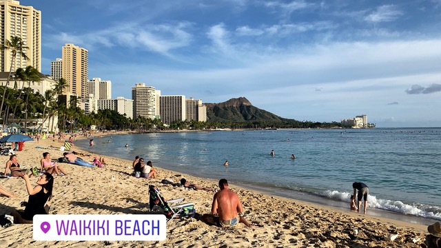 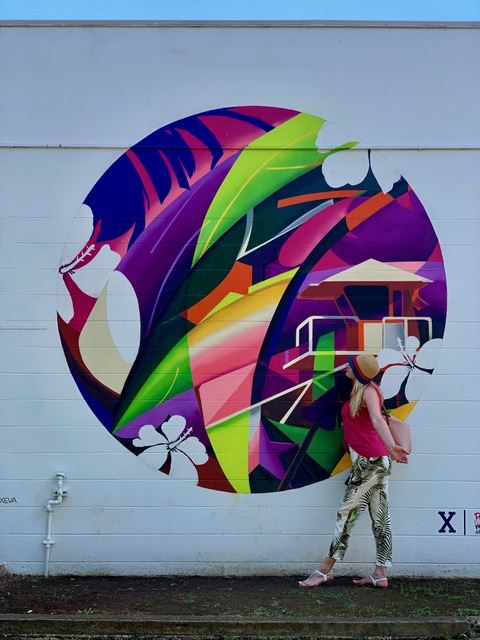  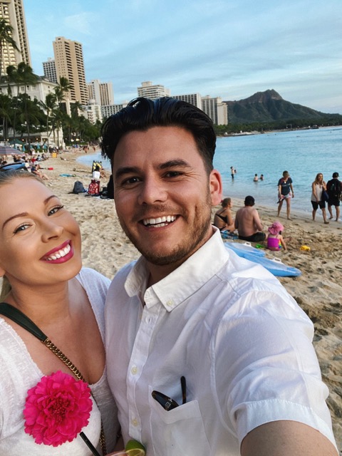 |
  |
1 User(s) are reading this topic (1 Guests and 0 Anonymous Users)
0 Members:

|
Lo-Fi Version | Time is now: 10th April 2025 - 04:23 PM |
Invision Power Board
v9.1.4 © 2025 IPS, Inc.


