|
|

|
Porsche, and the Porsche crest are registered trademarks of Dr. Ing. h.c. F. Porsche AG.
This site is not affiliated with Porsche in any way. Its only purpose is to provide an online forum for car enthusiasts. All other trademarks are property of their respective owners. |
|
|
  |
| bahnzai |
 Jul 19 2021, 09:59 AM Jul 19 2021, 09:59 AM
Post
#981
|
|
Member   Group: Members Posts: 336 Joined: 26-July 06 From: Columbia, SC Member No.: 6,509 Region Association: South East States 
|
Well, I got a bit out of sequence, but the engine intake / fuel-system overhaul proceeds. Decided to nix the idea to match the Intake manifold to the color of the shroud in-front, and went with a satin black. As for all the equipment like the nuts, bolts, straps and brackets; I've sent those all to plating to match and hope to get them back Monday. While I posted a thread on painting the manifold that received mixed feedback on painting the manifold, I had success using SEM 'trim' black as well as an adhesion promoter. In general, I thoroughly degreased and cleaned the manifold before rinsing it several times in simple water to make sure all the cleaning materials were off. After letting it sit for about 24-hours, I used sanding paper to take away any big dents and scotch-bright to prep the surface before rinsing in water a final-time. Two coats of adhesion promoter 10 minutes apart, then three coats of trim black before letting them hang for 24 hours. I'm very pleased, these look alot less-weathered. The manifold is getting all new fittings and hoses as well as the previously mentioned fuel-lines (Thanks Pelican 0 Pelican Parts. Pulling the injectors and fuel-rail I'm happy that all were working and in very good condition (They run about $250 per-injector... yikes! (IMG:style_emoticons/default/blink.gif) ) so no need to replace. I have cleaned out and also ordered all-new O-rings as well as gaskets for my previously VERY dirty) manifold and throttle-body. Hoping to start updating next-week with some engine / parts-bling photos. (IMG:style_emoticons/default/bye1.gif) Rique, I know that you are beyond this point, but some added info in case someone reads this down the road. When I had my 3.6 out last year for engine harness replacement (1995 Porsche recall item due to failing wire insulation), I had the fuel injectors rebuilt. I found the service through Rockauto.com at $32 per injector. Rebuild was:Removal of Surface Rust And Ultra-Sonically cleaned, Replacement of O-Rings, Seals, and Washers, Ohm and Flow-Tested to Ensure OE Specifications GB Remanufacturing Inc. Attn: R&R Department 2040 E. Cherry Industrial Circle Long Beach, CA 90805-4410 (608) 661-1376 |
| RiqueMar |
 Jul 19 2021, 11:59 AM Jul 19 2021, 11:59 AM
Post
#982
|
|
Enrique Allen Mar     Group: Members Posts: 2,208 Joined: 28-August 08 From: San Diego, CA Member No.: 9,478 Region Association: Southern California 
|
Rique, I know that you are beyond this point, but some added info in case someone reads this down the road. When I had my 3.6 out last year for engine harness replacement (1995 Porsche recall item due to failing wire insulation), I had the fuel injectors rebuilt. I found the service through Rockauto.com at $32 per injector. Rebuild was:Removal of Surface Rust And Ultra-Sonically cleaned, Replacement of O-Rings, Seals, and Washers, Ohm and Flow-Tested to Ensure OE Specifications GB Remanufacturing Inc. Attn: R&R Department 2040 E. Cherry Industrial Circle Long Beach, CA 90805-4410 (608) 661-1376 @bahnzai - Thank you Señor Danny! I was interested in this, but was having trouble finding a shop that offered the Service ice, currently, no problem with the injectors. I just reassembled everything to retest the wiring changes I made, and referencing a mechanic I'm working with, "Don't fix it until there is a problem" so I'll save this for later. In the meantime, I cleaned what I could and replaced all the O-rings. One of the things I'm grateful for during this intake rebuild was the understanding it gave me regarding all the equipment on the top of the engine as well as the connections; Vacuum lines, Wiring, etc.. Further, this is helping me understand what I'll need to do in the future, as I want some sort of ITB solution (PMO, AT Power, etc.) |
| RiqueMar |
 Jul 19 2021, 01:28 PM Jul 19 2021, 01:28 PM
Post
#983
|
|
Enrique Allen Mar     Group: Members Posts: 2,208 Joined: 28-August 08 From: San Diego, CA Member No.: 9,478 Region Association: Southern California 
|
Heading out on another round of business trips tomorrow, so spent the weekend wrapping up different items because the car is going back to European Motorsports while I'm gone. Now that I've either replaced or rebuilt all the intake manifold components and engine fuel lines, the guys at European will be giving it the final 'push' to make sure everything is hooked up correctly. I think I mentioned previously that, while everything worked there were alot of 'question-marks' about the installation in the previous car. Some of the things I found....
- Engine ECU was not getting constant 12v. This was causing it to 'reset' and 'relearn' each time it was started up. - Fuel pump was not connected to the DME relay, but rather directly to the ignition switch. - Different indicators were not connected, some of them.... pretty important. Alternator light, Engine Temp, Check Engine, Oil Tempt, Diagnostic Port, etc. In addition, I found I really needed a 'break' from the wiring sometimes, so I found small side-projects to do on the car - such as installing the air-horn, new 19mm Master Cylinder from 914Rubber and brake lines. Question for anyone reading this; I see that the electrical connections on the Master cylinder has 1-pole, however it looks like my wiring has 2x connections that don't lead anywhere, does anyone have any reference on this? (IMG:style_emoticons/default/bye1.gif) 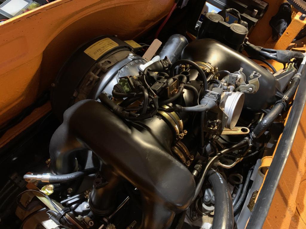 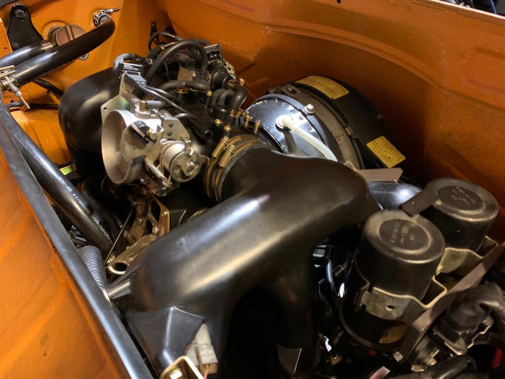 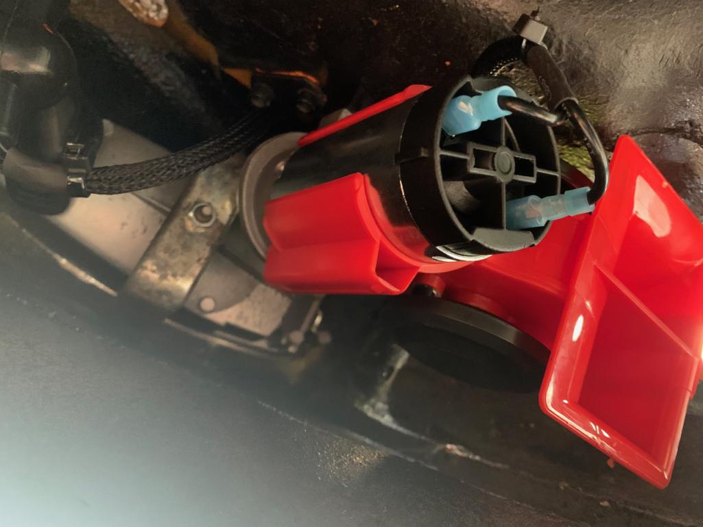 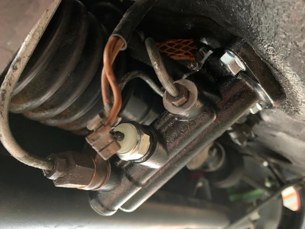 |
| mepstein |
 Jul 19 2021, 07:09 PM Jul 19 2021, 07:09 PM
Post
#984
|
|
914-6 GT in waiting                Group: Members Posts: 19,811 Joined: 19-September 09 From: Landenberg, PA/Wilmington, DE Member No.: 10,825 Region Association: MidAtlantic Region 
|
You just tie away the extra wire. Very common issue but it still works fine.
|
| RiqueMar |
 Jul 20 2021, 02:19 PM Jul 20 2021, 02:19 PM
Post
#985
|
|
Enrique Allen Mar     Group: Members Posts: 2,208 Joined: 28-August 08 From: San Diego, CA Member No.: 9,478 Region Association: Southern California 
|
You just tie away the extra wire. Very common issue but it still works fine. @mepstein - Thanks, this is a new area for me. I suppose I'll have to find the indicator for my brake warning light, seems easy enough, or I can add a light to the dash. (IMG:style_emoticons/default/idea.gif) |
| ValcoOscar |
 Jul 20 2021, 02:41 PM Jul 20 2021, 02:41 PM
Post
#986
|
|
Garage Life     Group: Members Posts: 2,493 Joined: 19-November 13 From: SoCal Member No.: 16,669 Region Association: Southern California 

|
I really like your wheels! They look mean. The grey has just enough contrast to stand out against the black - I wonder if you went darker whether they might just have looked one flat color in certain light? (IMG:style_emoticons/default/agree.gif) with John... I like the contrast, unique and tasteful. Just my 2 cents!!!! (IMG:style_emoticons/default/beerchug.gif) Oscar |
| RiqueMar |
 Jul 20 2021, 02:53 PM Jul 20 2021, 02:53 PM
Post
#987
|
|
Enrique Allen Mar     Group: Members Posts: 2,208 Joined: 28-August 08 From: San Diego, CA Member No.: 9,478 Region Association: Southern California 
|
Car is off to European Motorsports again this morning! I was happy when the Owner, Joe, commented on the work I did on the Engine-bay and intake manifold. Before loading it up last night, I wanted to wrap-up the Fuel-system and anything located below the tank. Though its not necessarily difficult, it's not exactly 'fun' getting in there and I want it done with once-and-for-all.
First up, the fresh air-box. While connecting the old drains after installing the windshield washer pump, the ribbed-plastic simply broke (too old). Thanks to Bruce Stone, he recommended irrigation / drain-hose from Lowes. I was able to rig up a solution that will last alot longer, not break, and even has a barb and nut that holds it to the bottom of the car. For this, I used a 7/8 ID x 1-1/4 hose, the original plastic 'Y' connector, and a barb / threaded pipe fitting with a 1" nut to hold it to the floor-pan and a hose-clamp for the very-bottom connection. (IMG:style_emoticons/default/cheer.gif) Last item before putting in the tank, the fuel evap. and overflow hoses. For those looking for a solution, visit the 'Fuel and Exhaust' section of the 914Rubber.com website. Mark and his crew have a whole setup, from the overflow lines to the grommets and plastic lines that run to the engine bay (I'll have to figure out where to connect them on my 3.6 manifold, or just exhaust out the bottom of the car). I haven't hooked up the lines completely, but everything is run. Pro-tip when installing the over-flow hose, I found it was a really tight fit, and couldn't get it onto the tank fitting. I ended up putting a pair of pliers into the hose, opening them, and then holding that end in-front of a heat-gun. It will give you just that extra space you need. Off to a trip now, hoping the car will be ready for pick-up when I get back. If not, sounds like I'll be focusing on refurbishing parts, and painting bumpers and valances. (IMG:style_emoticons/default/bye1.gif) 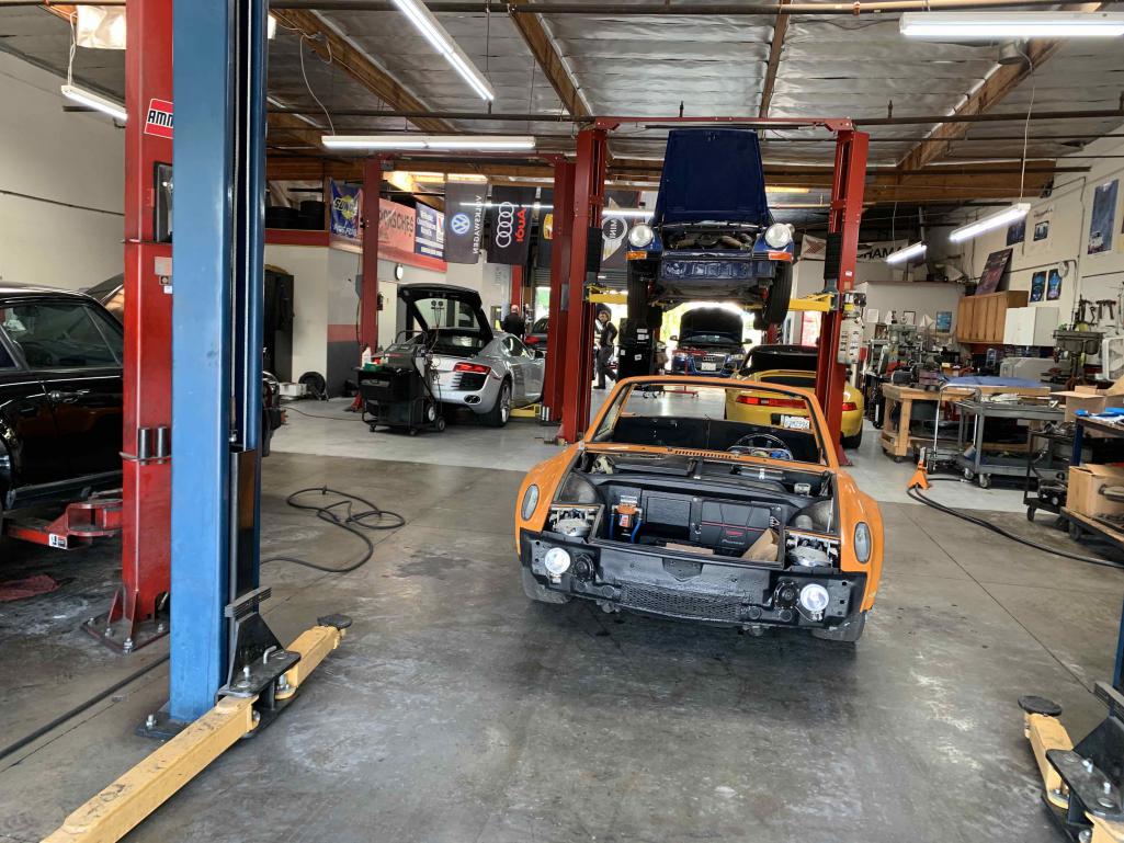 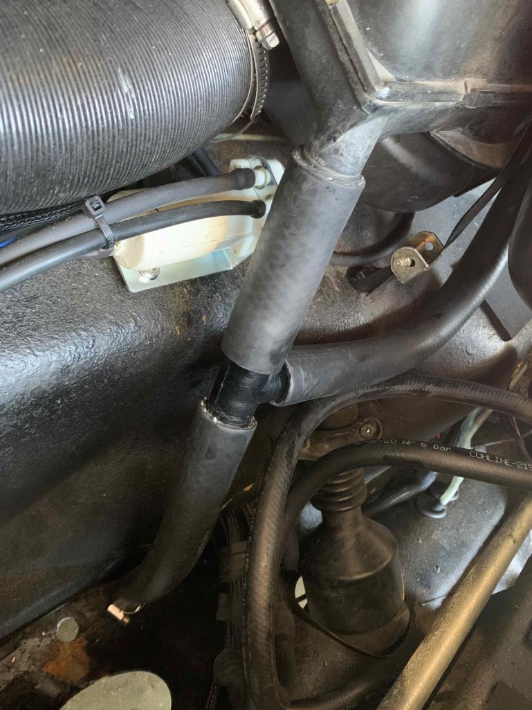 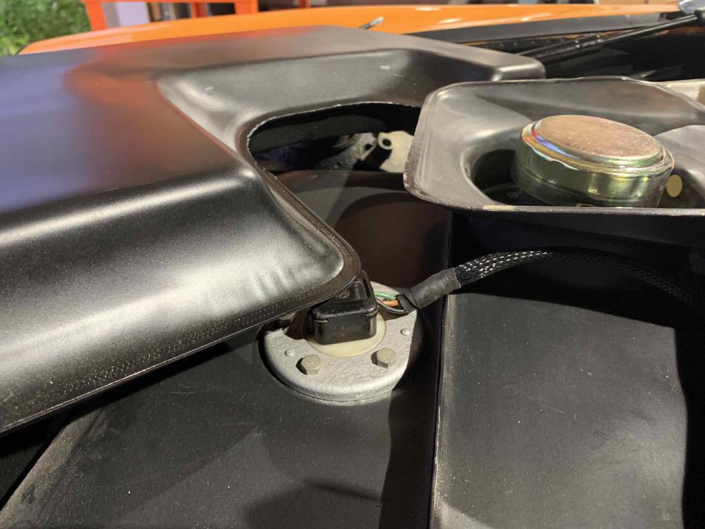 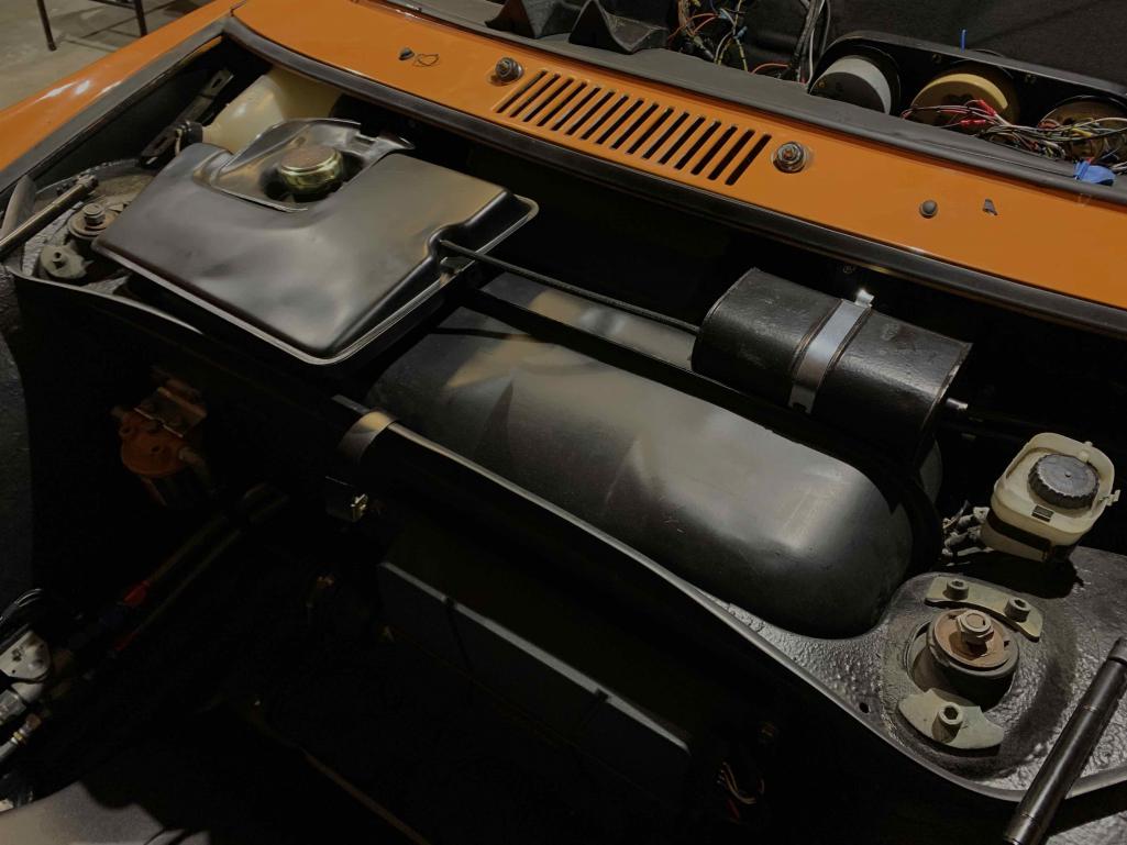 |
| RiqueMar |
 Aug 9 2021, 02:56 PM Aug 9 2021, 02:56 PM
Post
#988
|
|
Enrique Allen Mar     Group: Members Posts: 2,208 Joined: 28-August 08 From: San Diego, CA Member No.: 9,478 Region Association: Southern California 
|
Unfortunately, the guys at European weren't able to finish this off before a vacation break, so the car will be back in a couple of weeks. In the meantime, I'm wrapping up 'odds and ends' and trying to carve out 1-2 hours a day to do the little-things; Bumpers, Interior, trim, whatever I can find.
Last-weekend, I was able to carve out some time to give the bumpers a final-pass before paint. Though I had originally planned to spay them with a paint-gun, I have had great experience with SEM in a can lately and figured I would give it a try and use this coat as 'primer'. I'm happy to say that if these are given the right amount of prep, use adhesion promoter, and painted in the right-environment the 'rattle can' approach is VERY good. As with anything paint / bodywork related, you get what your pay/prep for. Previously, these were cut, modified and blended for my GT Cooler and then sprayed with 'feather-fill', so they only needed a bit of polyester for a few small details. I stayed away from the pneumatic and electronic tools (jitter-bug) to avoid any accidents. With the polyester-filler placed in certain spots, I started off with 480 grit, then moved to 800 and finished with 1000 wet/dry. Final prep was with a bit of scotch-brite. Then, 2-coats of adhesion promoter. A 10-minute wait, and I finished with 3-coats of SEM 'trim-black'. About 1-can per-bumper, though I also painted my sail-panel trim during this session. Note - To give those less-experienced with bodywork, I'de like to give you an idea of the labor put into this. Everything described in the paragraph above, from beginning of prep to painting, took about 6-hours. This does not including the shaping and initial bodywork done previously. It's fair to say that, depending on the condition of your bumpers, starting a project like from scratch can easily take 20-hours of work, without factoring in disassembly/reassembly, sourcing the paint and supplies (not to mention material-cost), and rework. Just my feedback, but I would factor that into your estimation when considering how long this will take, doing it yourself, or contracting. Pro-tip: See the last-photos of the bumpers staged before painting? It would have been much easier if I would have 'rotated' each bumper 180º so they would face 'out' due to the 'curve'. Something I realized 1/4 of the way into painting. Rear bumper - top toward the painter / Front bumper - bottom toward the painter ** Edit: Weird, I thought I had some 'after photos', but everything is during prep and setup. I'll have to add some later. ** 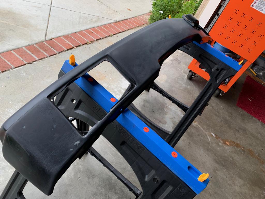 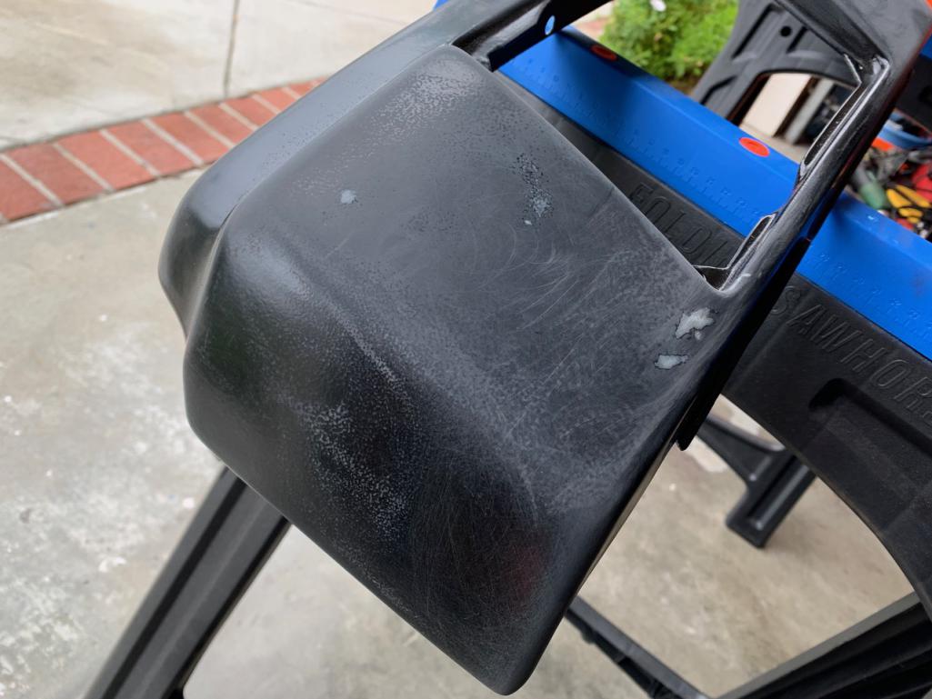 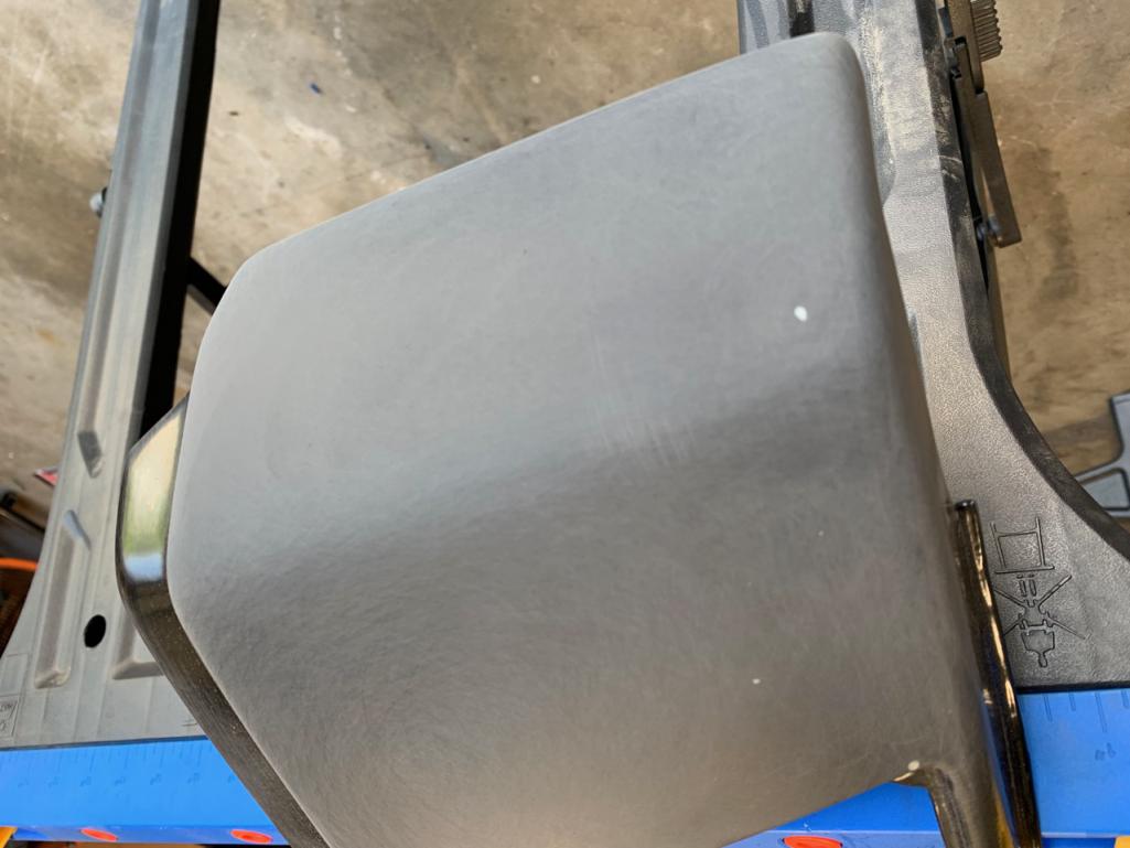 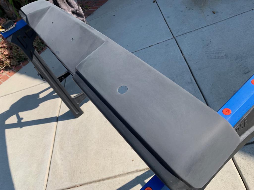 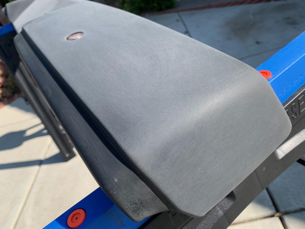 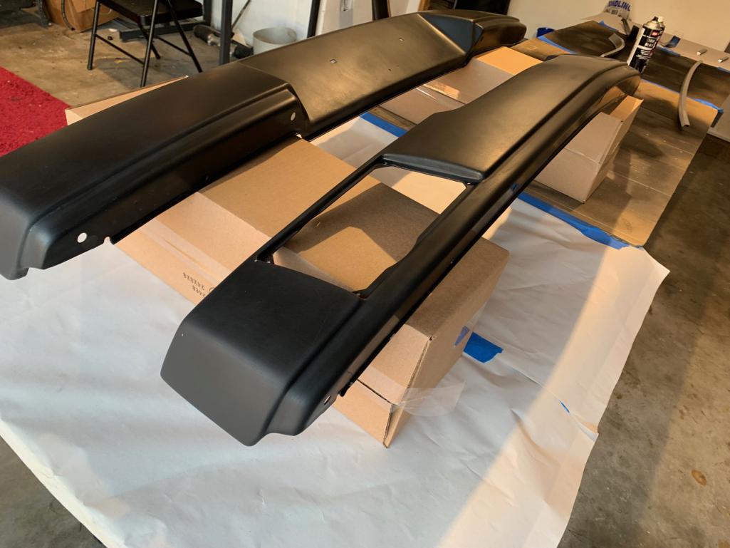 |
| RiqueMar |
 Aug 9 2021, 03:39 PM Aug 9 2021, 03:39 PM
Post
#989
|
|
Enrique Allen Mar     Group: Members Posts: 2,208 Joined: 28-August 08 From: San Diego, CA Member No.: 9,478 Region Association: Southern California 
|
For those following along, you may remember that last year I recovered my dash and put a material directly onto the dash-face at that time. This was a mistake. While it does work, and eliminated the needs for 'plates' and seems, it makes the whole thing difficult when adding a 914/6 ignition, trim pieces, etc. Further, you'll just find yourself MORE frustrated when you decide that you weren't as smart as the original designers and now have to strip all the glue and residue, mask-off, and repaint the front of the dash. (IMG:style_emoticons/default/headbang.gif)
To resolve this, I set out to find 914/6 dash panels, but they were either not available or really poor quality. When I couldn't find anything, I decided to make my own via laser cut. Those interested, see my previous post in the garage here > Gauging Interest - 914/6 dash panels. I started off with a cardboard model to get my dimensions correct, and have since cut with ABS to verify with a less-forgiving material. Making some modifications to this, I think, for my car atleast, I'll combine the radio plate with the rest of the right-panel as its weird to me that there is a seam right in the middle of the dash. Not sure which material I'll go with yet for the covering, but I'm certain that the plates will be aluminum. This way, owners can use them covered or uncovered. (IMG:style_emoticons/default/bye1.gif) 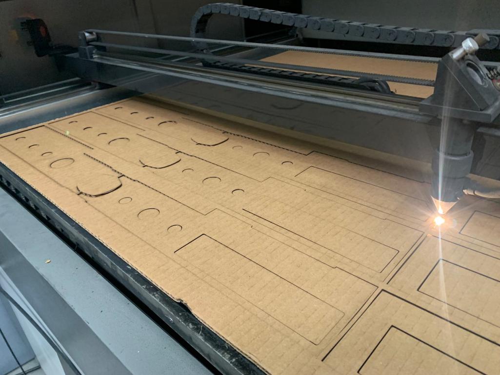 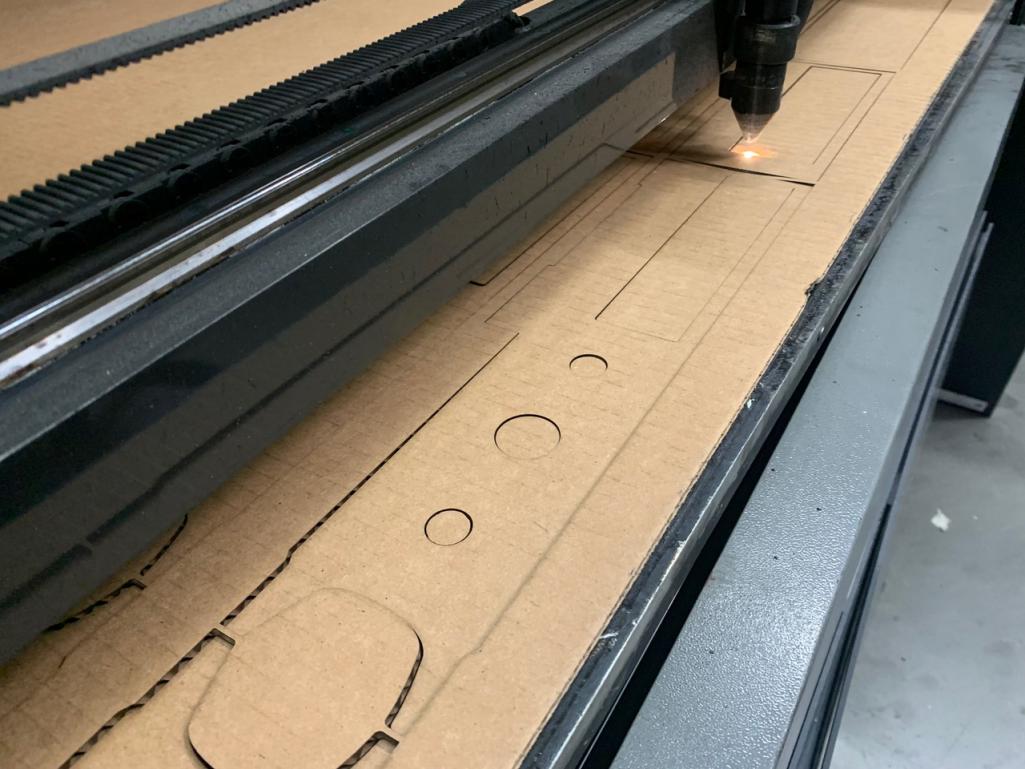 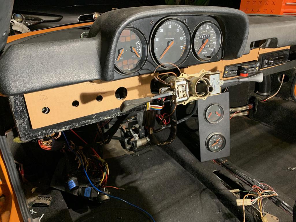 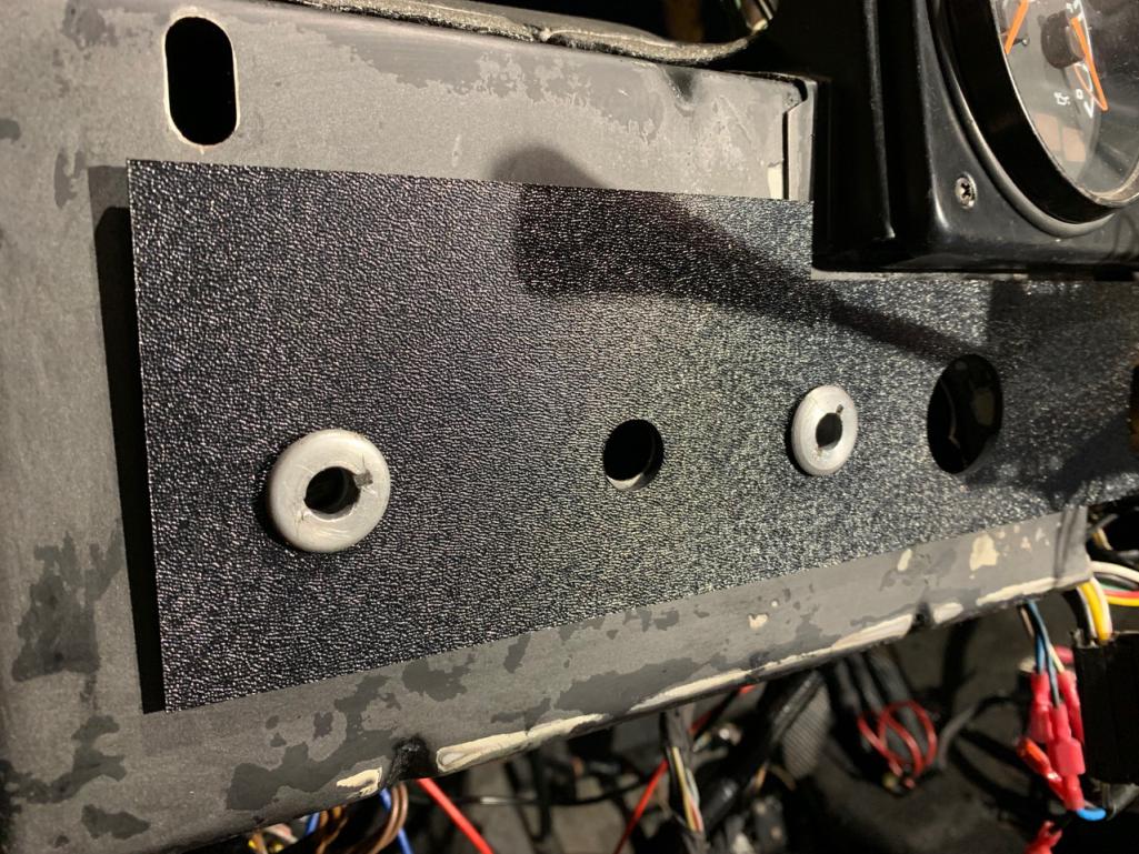 |
| RiqueMar |
 Aug 9 2021, 05:07 PM Aug 9 2021, 05:07 PM
Post
#990
|
|
Enrique Allen Mar     Group: Members Posts: 2,208 Joined: 28-August 08 From: San Diego, CA Member No.: 9,478 Region Association: Southern California 
|
My most recent work, the roll-bar vinyl and trim. I'm doing a short summary write-up on this for those out there that also have this on their 'to-do' list, as it is not necessarily 'difficult', though it can go wrong in a hurry, be very frustrating, cost-time, and be demoralizing. If you're interested or planning to do the same; Before you go any further read this write-up done by Eric Shea Sail Panel Vinyl Installation. Have you read it? Good, now read it again. After reading, you'll be familiar with the general process and have an idea of all the supplies needed. As a note, 914Rubber stocks the vinyl material and I recommend using 3M-90 spray adhesive. It's forgiving and easy to use.
This project, like so many others, is ALL about prep. This was actually my second-time applying the vinyl as my first went very-wrong at the end and resulted in about 1/4" of the paint showing. When I tried to correct, I was able to 'reset' one side, however the driver-side cursed, and I had dry-adhesive under the vinyl. (IMG:style_emoticons/default/headbang.gif) Shout out to the whole 914Rubber team for sending me a replacement piece! Before even starting, I layed out the vinyl overnight so that it will 'lay flat'. I suppose you could also let it sit in the sun, though I would make sure to let it cool as it might expand. Then, I prepped my roll-bar by using a bit of scotch-brite and wiped it down with 'Odorless Mineral Spirits' to eliminate any residue. After that, I masked off the area (I'm only doing the top of the roll-bar) and used tape to 'mark' where my vinyl should end-up. Pro-tip: Before you start spraying adhesive on the car or vinyl, take a few 'test passes' on any extra paper. This will help you anticipate the width of the spray and how you'll lay it down. After that, it's the fun part - spaying. Spray 2-3 coats on the body and 2-3 coats on the vinyl and let it 'sit' until you can touch it with your knuckle and the adhesive doesn't transfer. I did notice that mine went faster than expected, so take the 2-3 minute warning for what it is, a suggestion. Before applying the vinyl to the car, remove the masking. Reminder, it's easy to forget about the marks made on the masking so be sure to not remove those until you're done.... I made that mistake and suddenly realized I was flying solo and risked another wasted piece. Luckily, everything lined up, and I only needed the smallest amount of glue to 'reset' the Drivers side. If you catch it fast enough, when you spay more adhesive, the existing glue will 'reactivate'. You can see this in photo number 5. With the vinyl down make sure there are no creases/bubbles and the trim and roll-bar pads will cover the edges, I suggest massaging the piece for the first 5-10 min. After, give everything at least a good 60-min (longer is better) to set before trimming. Trimming is pretty straight forward as the sail-panel aluminum sits flush with the top of the roll-bar, as does the interior pad. Once everything is trimmed, you can then re-apply or apply your new trim. I struggled with this a bit, as I didn't remember exactly how everything went together, so I've included various photos of the brackets and trim to show their orientation. Note here: The zinc-plated brackets you see in the picture with the Drill? Those actually slide into the long trim piece, I just had them on the car to test fit on the body-trim and measure out where I wanted them to go (4-inches in on each side, the center bracket sits in the middle at 23" from either side). Another Note: The satin-black trim pieces that you see on either-side of the vinyl are purchased from 914 rubber. THEY ARE side specific. It's pretty obvious which-is-which once you see that the 'squared' side is the rear, and the 'angled' side is the front. Another Note: The zinc plated brackets that you see next to the engine grille? Tighten these down BEFORE you secure the 'swooped' pieces. If you have a 914/6 or 6-conversion with an oil tank.... Make sure you put that in BEFORE the oil tank.... ask me how I know. (IMG:style_emoticons/default/dry.gif) (IMG:style_emoticons/default/bye1.gif) 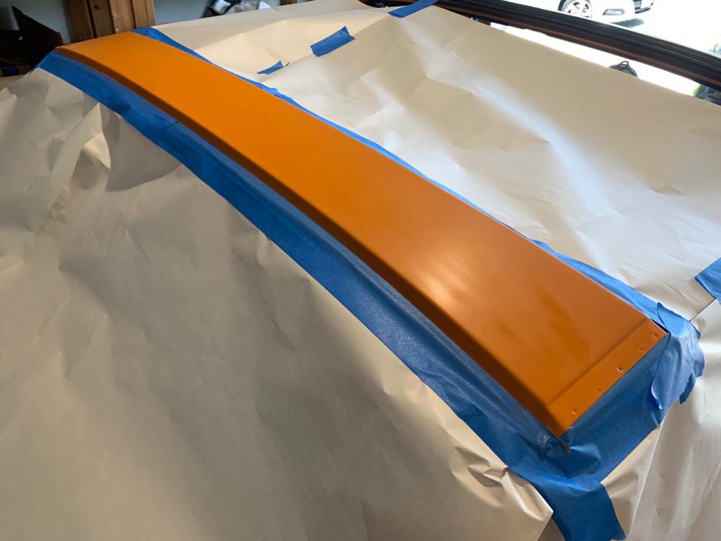 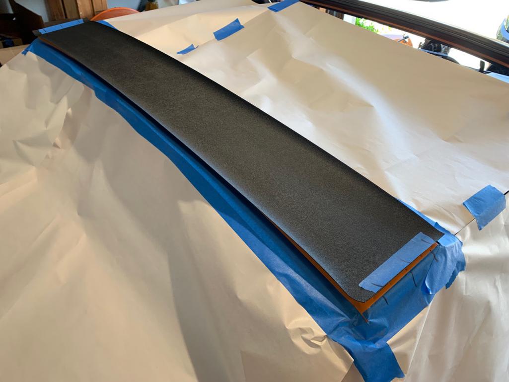 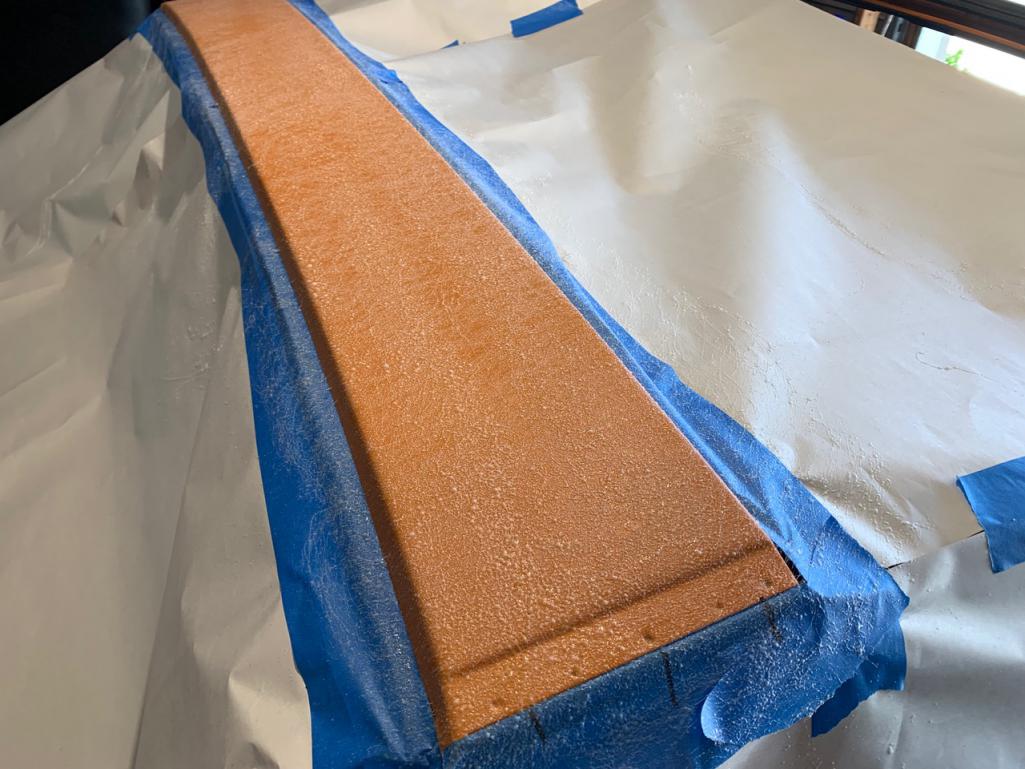 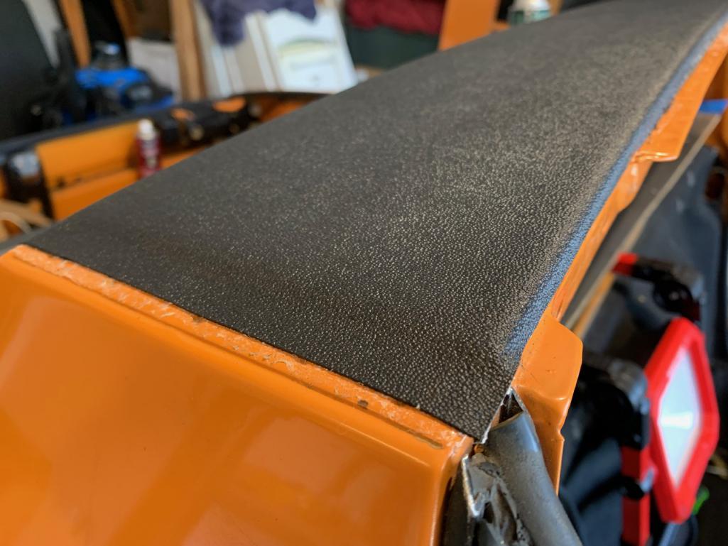 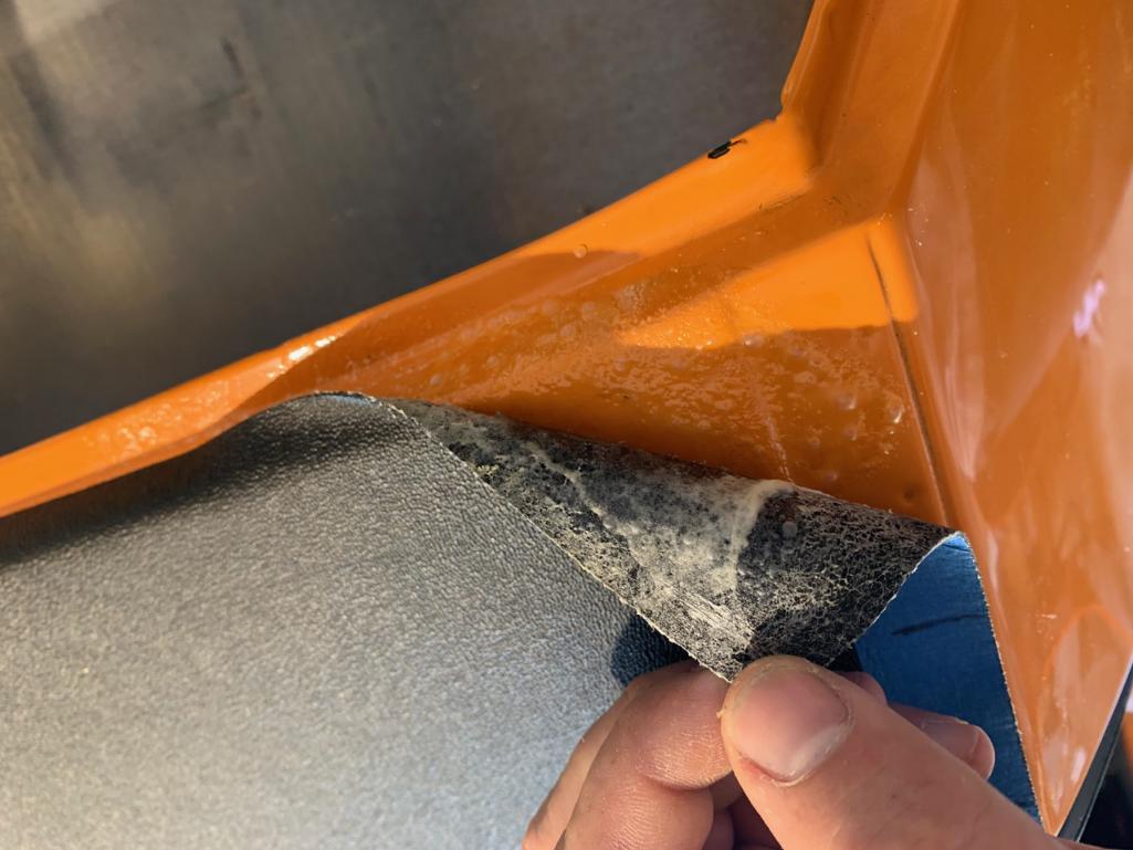 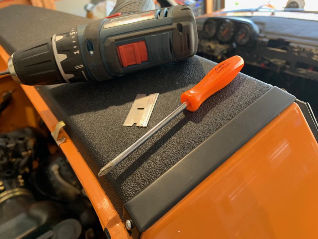 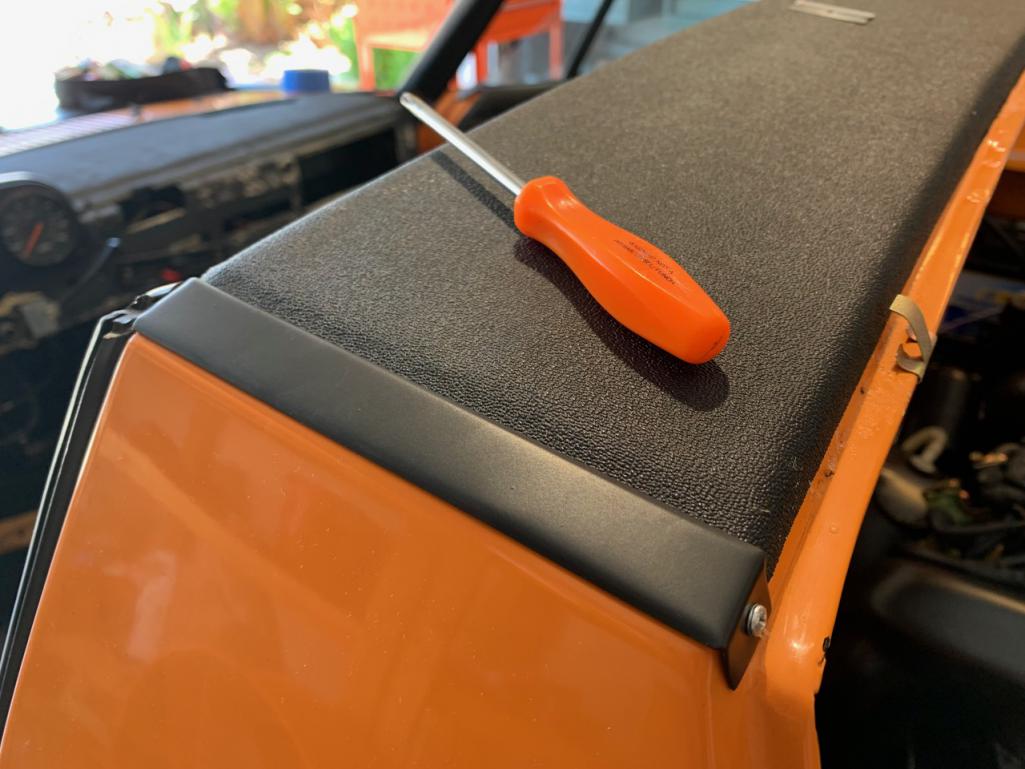 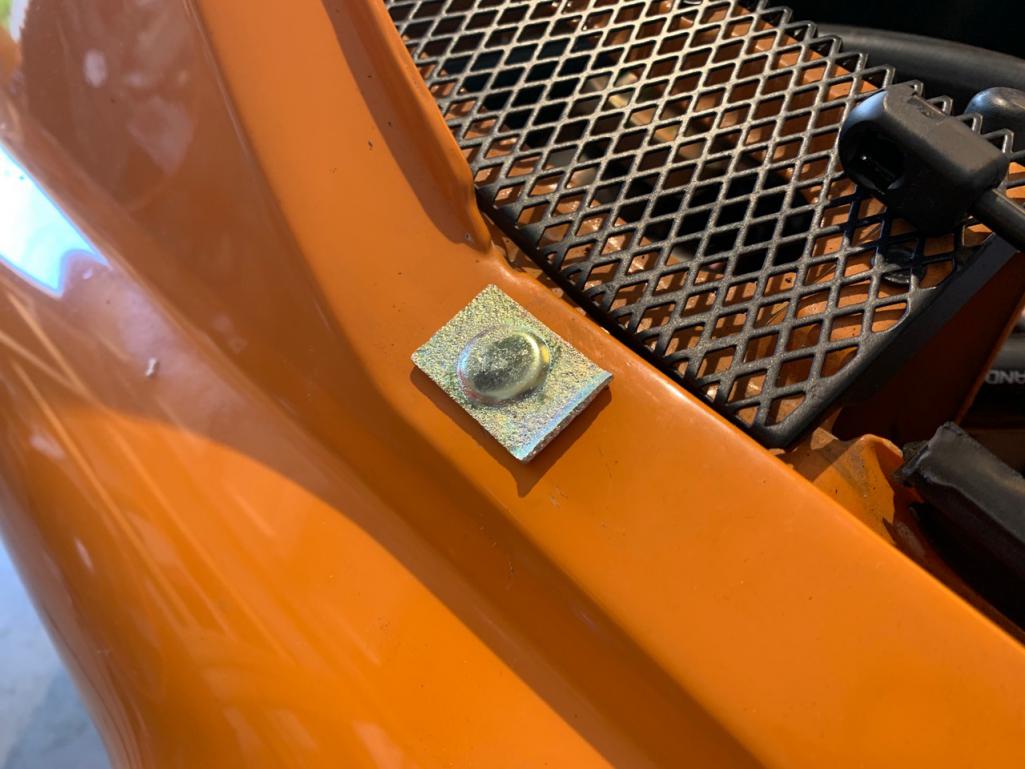 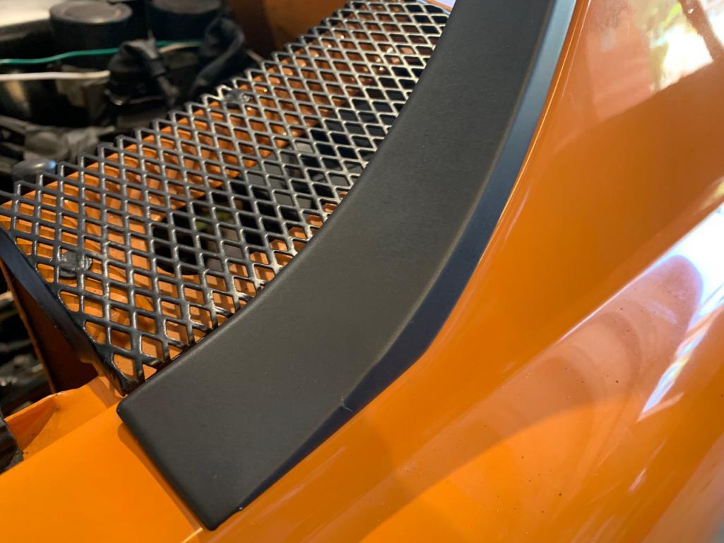 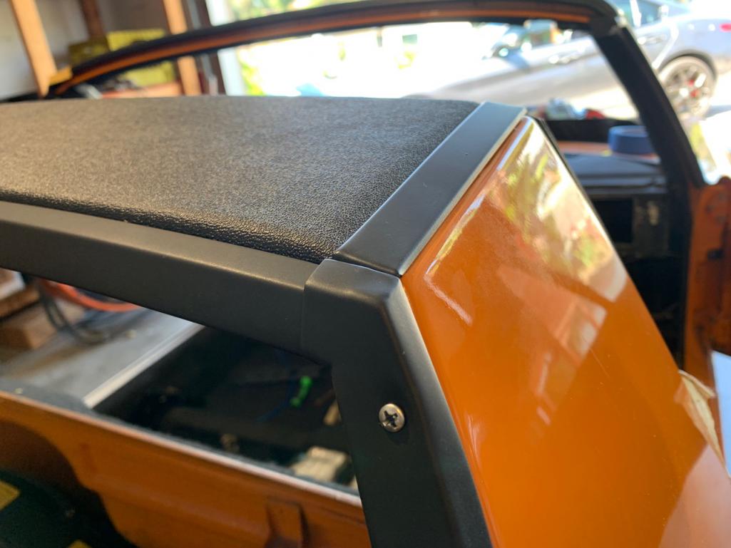 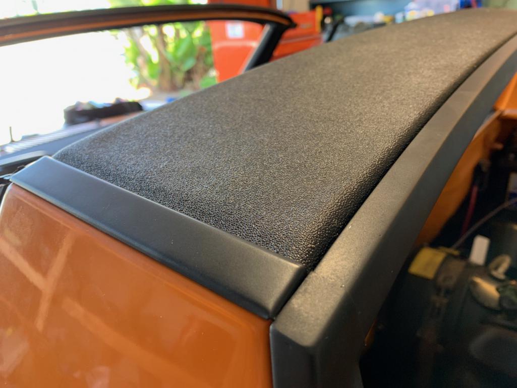 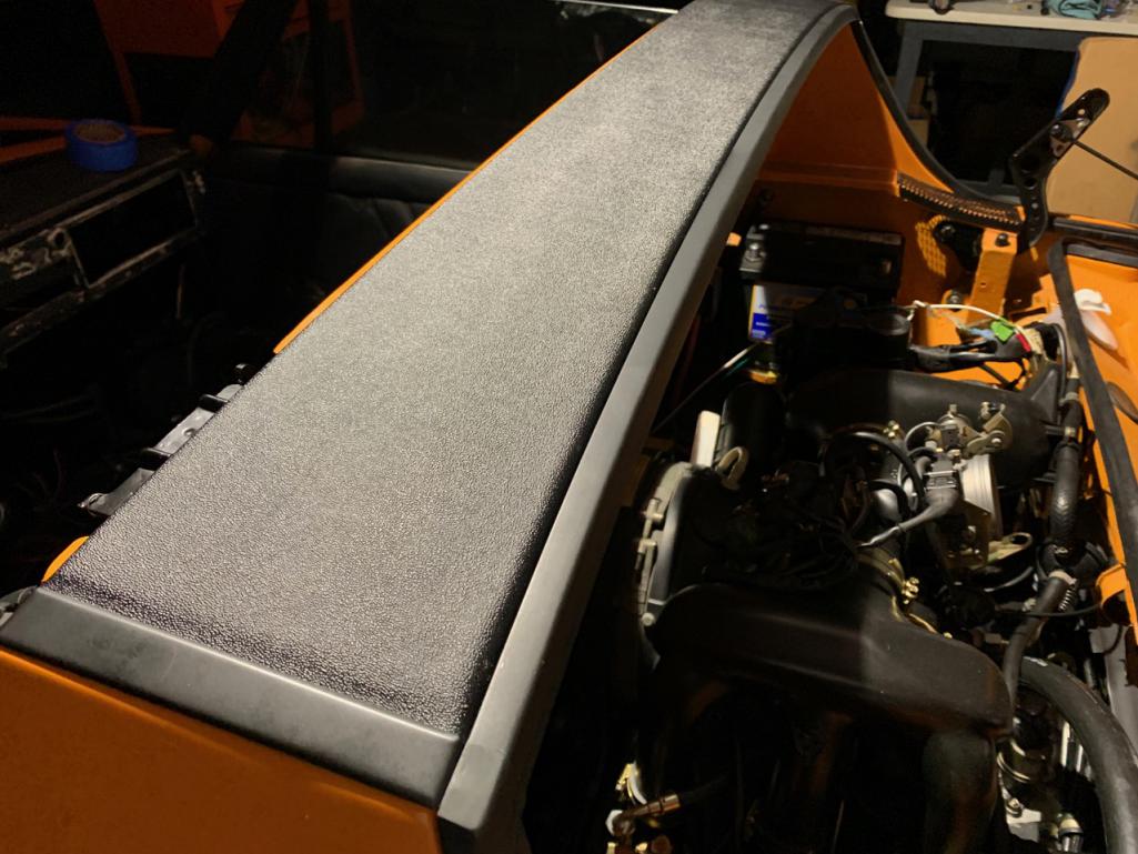 |
| autopro |
 Aug 9 2021, 09:58 PM Aug 9 2021, 09:58 PM
Post
#991
|
|
Member   Group: Members Posts: 306 Joined: 14-January 18 From: San Diego / Tijuana Member No.: 21,797 Region Association: Southern California |
This is great, thanks for the links and the advice. I'll have to do this in the future and your pictures will be very helpful. Thanks!
|
| RiqueMar |
 Aug 11 2021, 10:34 AM Aug 11 2021, 10:34 AM
Post
#992
|
|
Enrique Allen Mar     Group: Members Posts: 2,208 Joined: 28-August 08 From: San Diego, CA Member No.: 9,478 Region Association: Southern California 
|
Posting a 'How-to' regarding the removal of the front-trunk pull-handle. Usually, this is done for cleaning and lock replacement, or in my case - both. Looking through the site, I felt like this last part of the project is unrepresented, so sharing the steps I took to remove. It's pretty easy, and only take about 5-minutes.
For the first step, I don't have a picture, you need to make sure you can access the bottom of the handle to remove 1x flat-head screw (you'll see it in the last-photo). This means you might have to remove your speaker-grilles or anything blocking the bottom of the handle. It's pretty short, and only needs a few turns. Next, move to the front trunk and loosen the bolt that holds down the pull-wire, located inside the mechanism that locks the front-trunk. Straightedges the wire a bit, as much as you can, so it won't 'drag' inside the wire guide. Next, loosen the Phillips-screw that holds the wire-guide on the outside of that same mechanism. Now, move to pull the handle out of the slot. You only need to pull it out about 6-8 inches. From here, you'll notice that the handle is 'theaded' onto the release wire. Note more-or-less where it is so you don't have to re-adjust when you install the handle. All you need to do is rotate it a few-times, and it will disconnect. In the last photo, you can see the screw from the first step. (IMG:style_emoticons/default/bye1.gif) 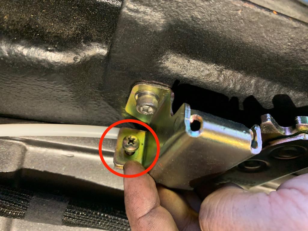 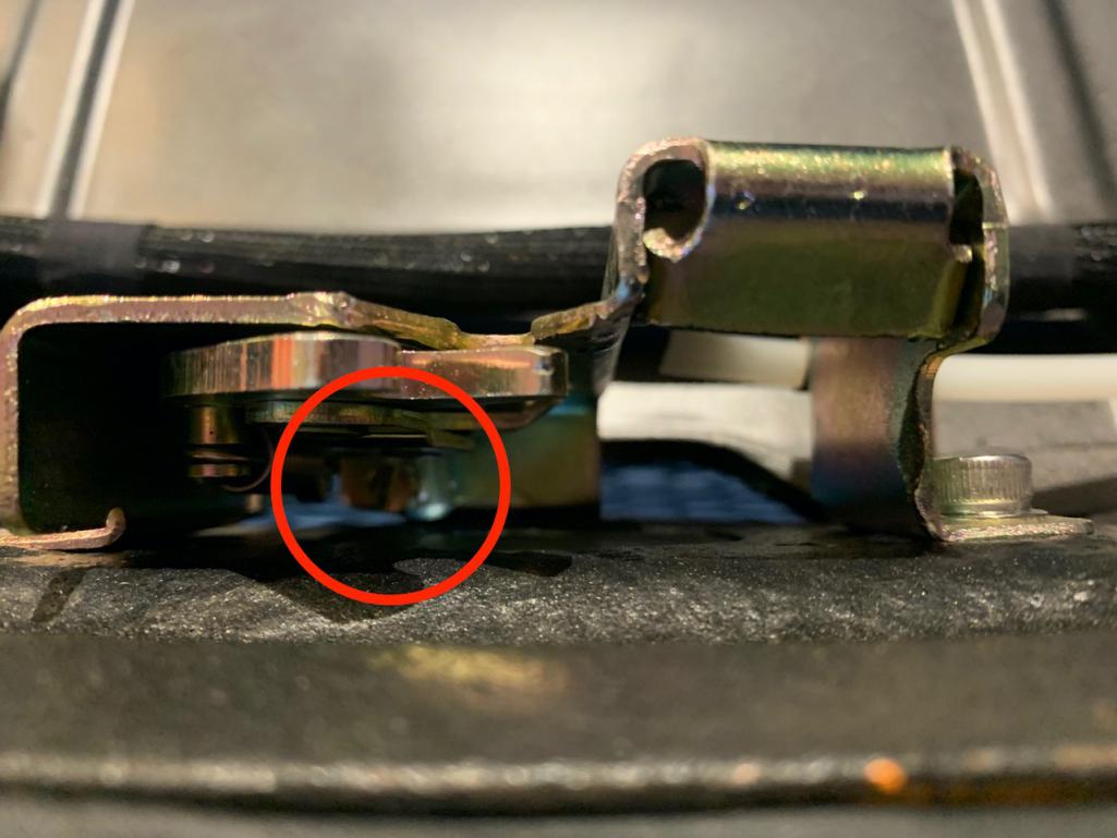 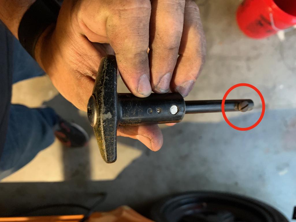 |
| RiqueMar |
 Sep 7 2021, 03:00 PM Sep 7 2021, 03:00 PM
Post
#993
|
|
Enrique Allen Mar     Group: Members Posts: 2,208 Joined: 28-August 08 From: San Diego, CA Member No.: 9,478 Region Association: Southern California 
|
Since my last post, I made a stop at Werks Reunion and thought I'de share a few photos. Great to see and meet everyone as well as see all the great cars. I especially enjoyed all the modified and 'custom' approaches to the various Porsche models!
Hopefully someday, I can be a part of this great get-together! 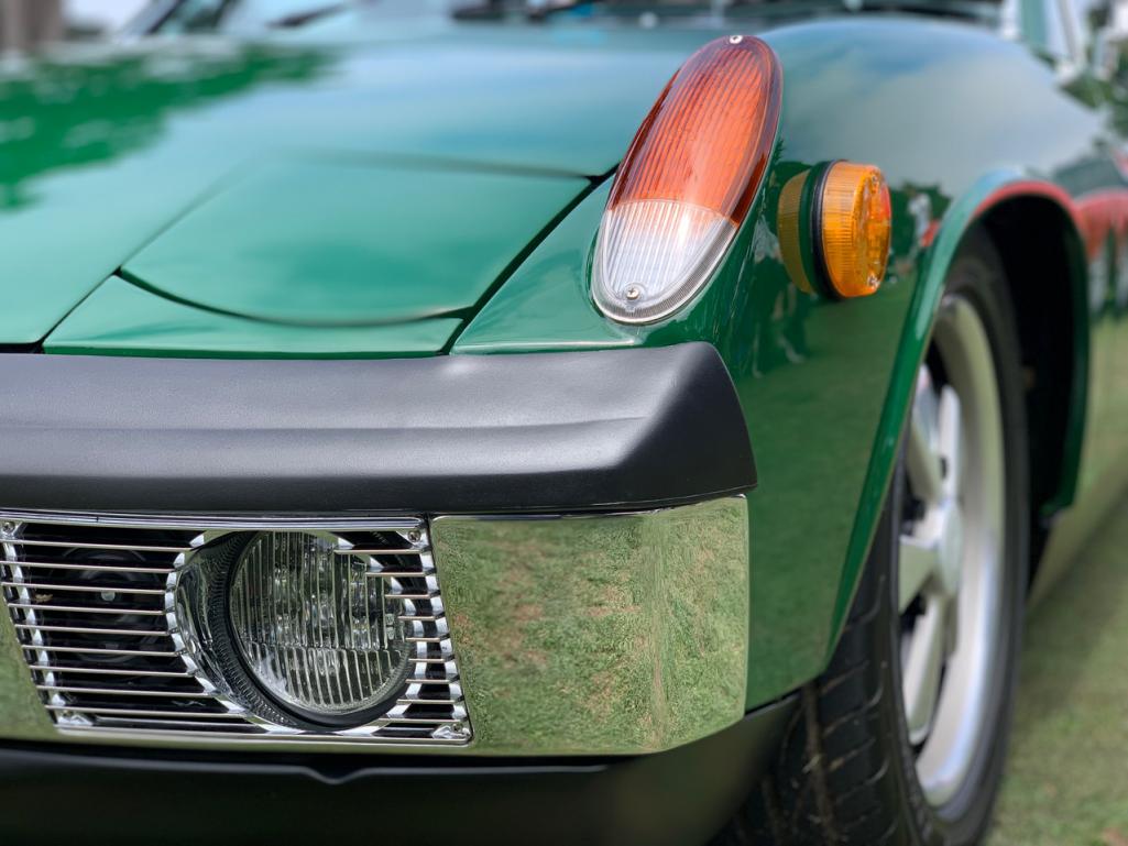 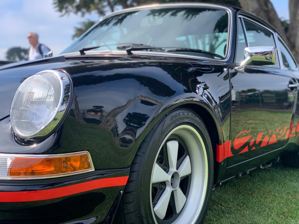 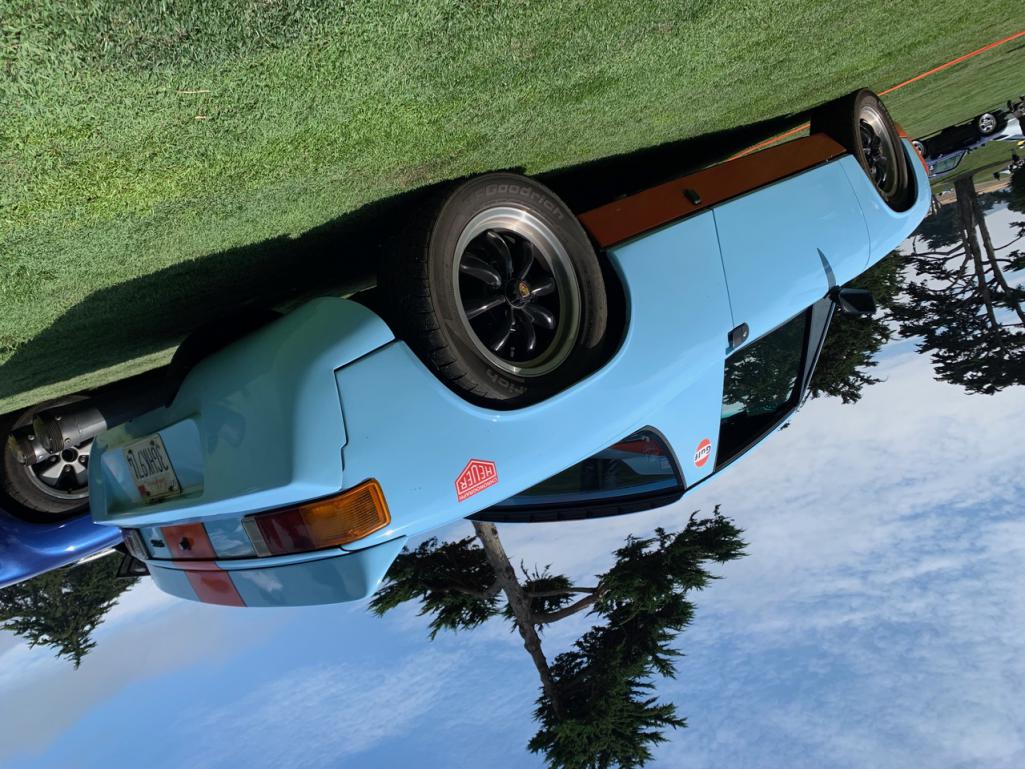 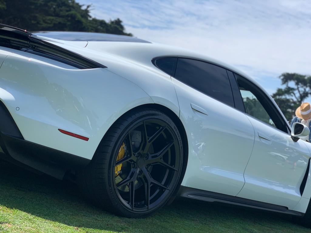 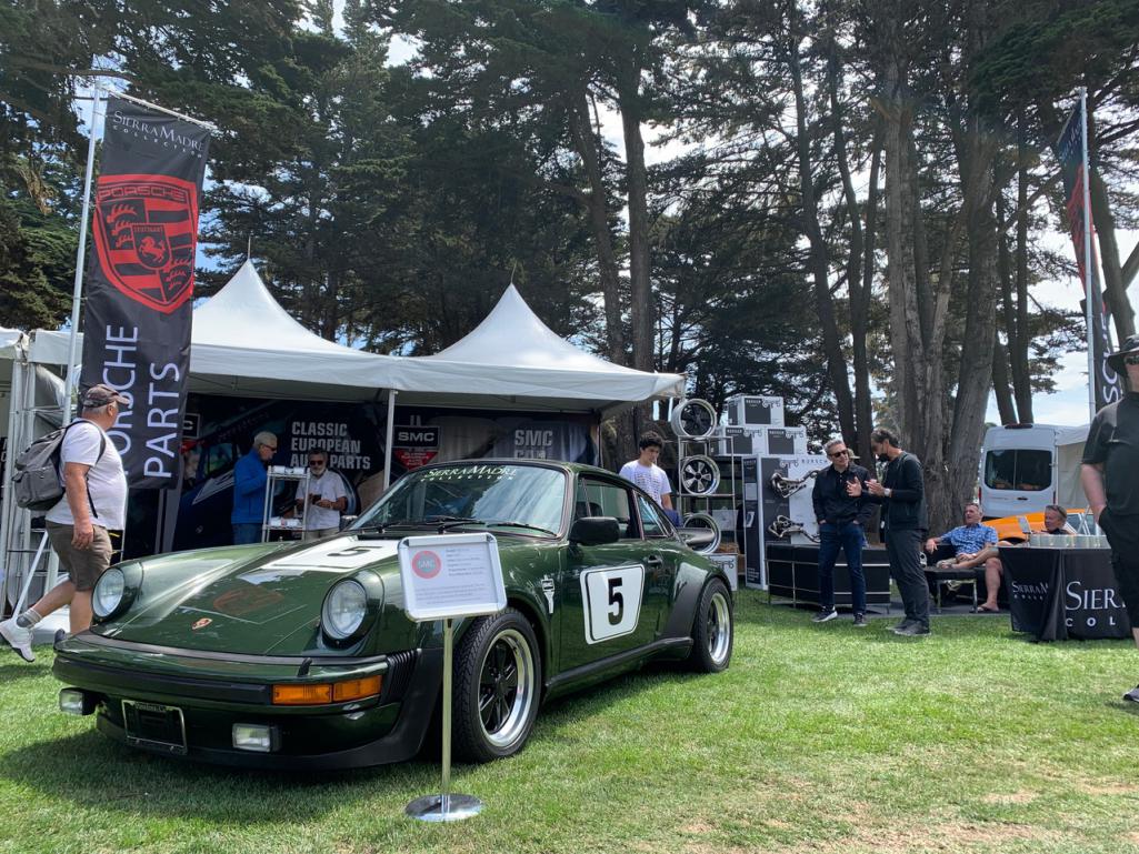 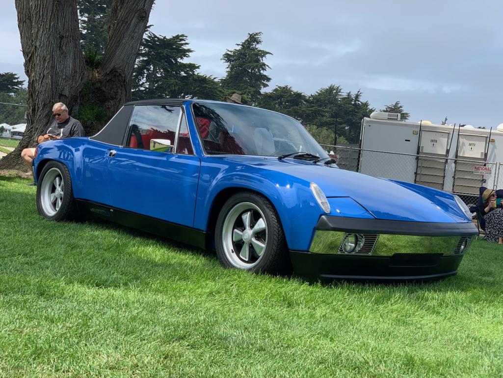 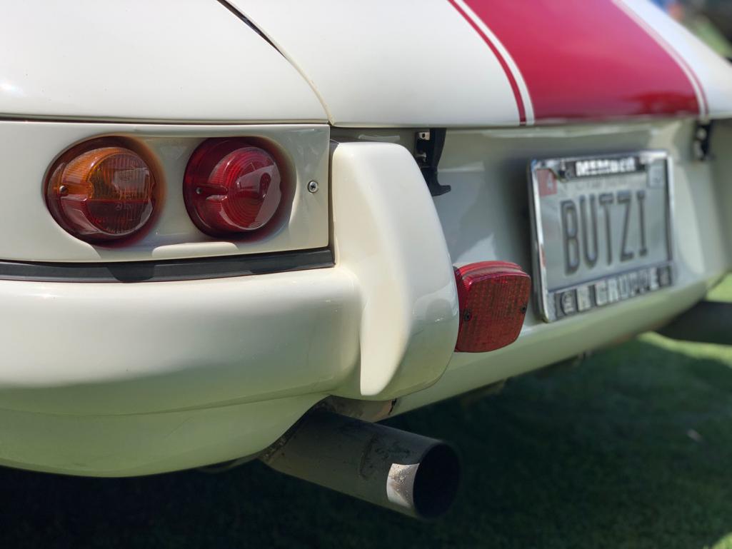 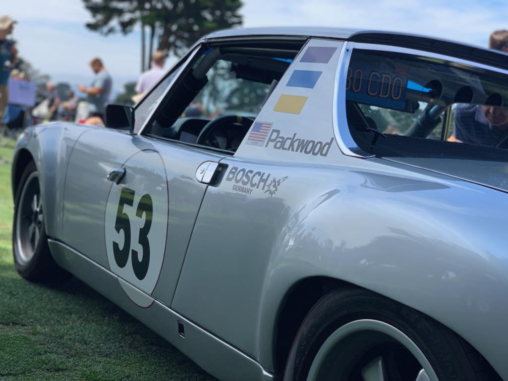 |
| RiqueMar |
 Sep 7 2021, 03:39 PM Sep 7 2021, 03:39 PM
Post
#994
|
|
Enrique Allen Mar     Group: Members Posts: 2,208 Joined: 28-August 08 From: San Diego, CA Member No.: 9,478 Region Association: Southern California 
|
Since my last post, I've been hot on the car, stealing an hour or two whenever I can. Alot of progress was made after I picked it up from it's last-session at European Motorsports. We seem to have developed a pretty good cycle of dropping the car off to get items functioning, and then I take out back to the garage to clean up or sort everything out. At this point, the motor is functioning normally, as well as the gauges and status lights (Check engine, Fuel gauge and Light, Alternator Light, Oil Pressure, etc.). Though it came back as a 'rats nest', I'm very happy with the result in sorting it all and making a new section of the harness.
Pro-tip: Work like this is tedious. The following photos don't do the portion of this project justice. All-in-all, just organizing and forming the harness took me the better part of 20-hours. It will be 'messy' at times, so I've found that the best practice is to jump in and re-organize and clean-up every so often using male/female connectors to shorten and consolidate color-schemes and then replace those wires with the correct gauge or color-code. I used zip-ties (alot of zip-ties) to form a section, run the wires, cut and re-solder, only to find a better or 'cleaner' way as I proceeded. Patience is key. Once I had the general form down and 'tested' the startup every so-often, I used electrical tape to form the structure of the harness, and then wrapped everything with safety sheathing. For this specific section, I used an open-ended safety sheathing in case I have to get back in there. Finally, I added a fuse / ground block for everything related to engine management. For the time being, this keeps everything tidy, as well as keeps my options open for the future should I switch to a different engine management system (dare I say ITBs? (IMG:style_emoticons/default/w00t2.gif)) After the main ECU harness was done, I spent this last weekend sorting the center-console gauges and hooking-up the Diagnostic plug. Easy enough in my configuration, as there are only about 5-connections for various sensors, RPM, and codes. Though I'm not 100% sure where it will be located in the future, I'm currently thinking inside the center console or underneath the dashboard. We'll see. (IMG:style_emoticons/default/bye1.gif) 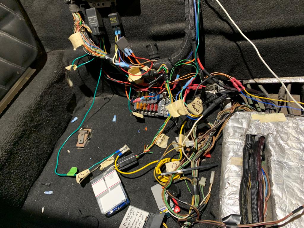 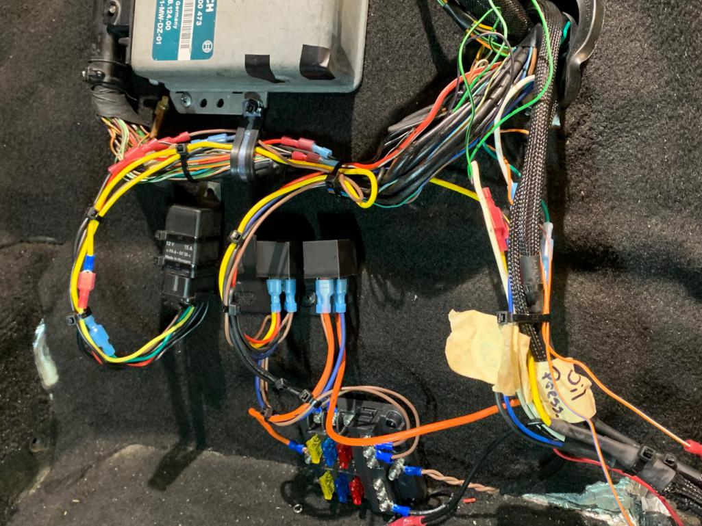 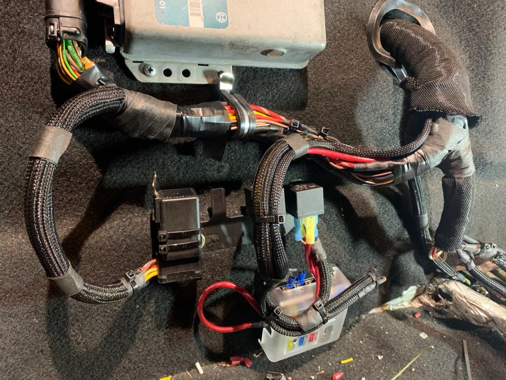 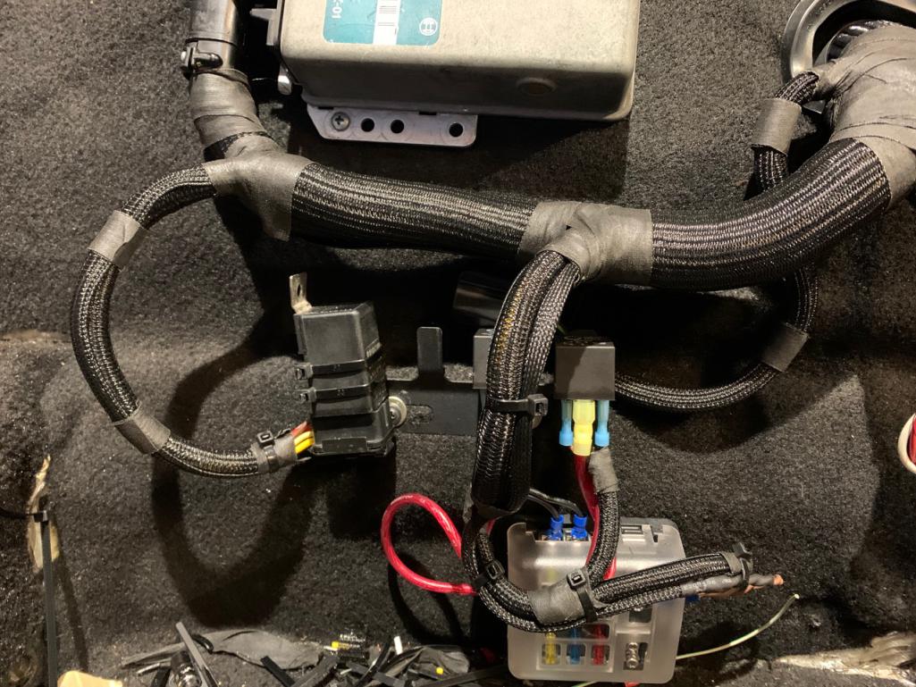 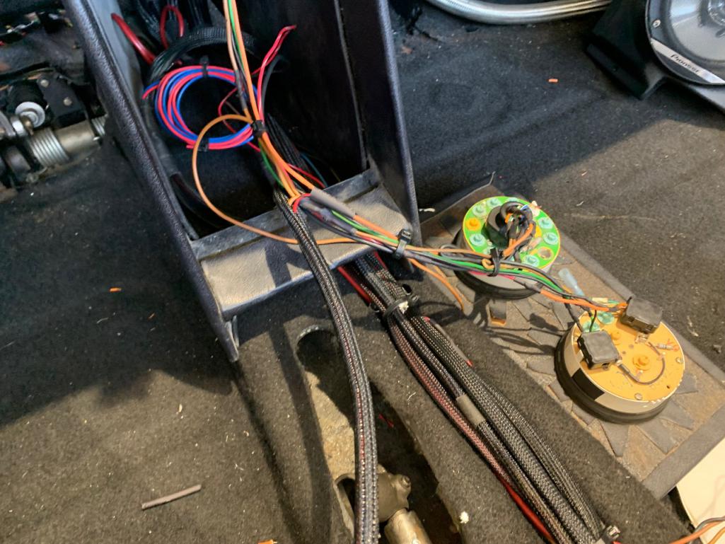 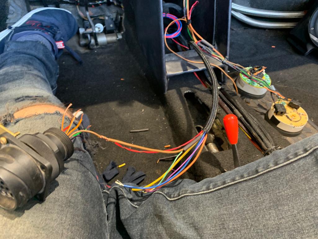 |
| RiqueMar |
 Sep 7 2021, 04:36 PM Sep 7 2021, 04:36 PM
Post
#995
|
|
Enrique Allen Mar     Group: Members Posts: 2,208 Joined: 28-August 08 From: San Diego, CA Member No.: 9,478 Region Association: Southern California 
|
In-between wiring (to keep my sanity) I've been trying to tackle the basic 914 related stuff; Clutch and Accelerator cable, Shifter and linkage, and Dash-fascia. Those following along will remember that a few weeks ago I was having trouble finding the dash-panels for a 914/6, so I made my own, and added some customization by combining the radio plate with the piece that starts on the Drivers right-side.
The first models were made out of aluminum and, even though I thought they looked great, I wanted to go with something a little more period-correct. I ended up settling on the early vinyl (thanks to 914Rubber), and am very happy with the result. Application is easy enough (follow this great video from Ian Karr found here > YouTube Link ). Pro-tip: Setup your work area in advance and don't be afraid to use a 'sharpie' to mark out your layout, it will help you both save material, and give you a good idea of how things will end-up. This is especially helpful for the area right before the glove box and around the 914/6 ignition key, there you have to cut and wrap the vinyl around the backside of the panel. I saved these challenging areas for last, once the majority of the glue had dried and set, and then cut slices so everything could 'lay' nicely. To make sure they stayed down, I held them to the piece with some blue painters tape for about 30-minutes. Another Pro-tip: To make your life a whooole-lot easier, you can remove the fresh-air control face. Just drill out the two rivets (seen in the photo, circled in red). From there, the slider-levers will pop out of the plastic. This will not only save the trim around the controls face from getting damaged (ask me how I know) but is waaaaaay easier than disconnecting the control wires, from the control or under the cowl. Once your dash-plate is on, just replace with 2x M4 screws. You can thank me later, beer appreciated. 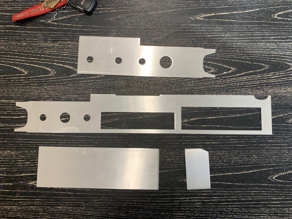 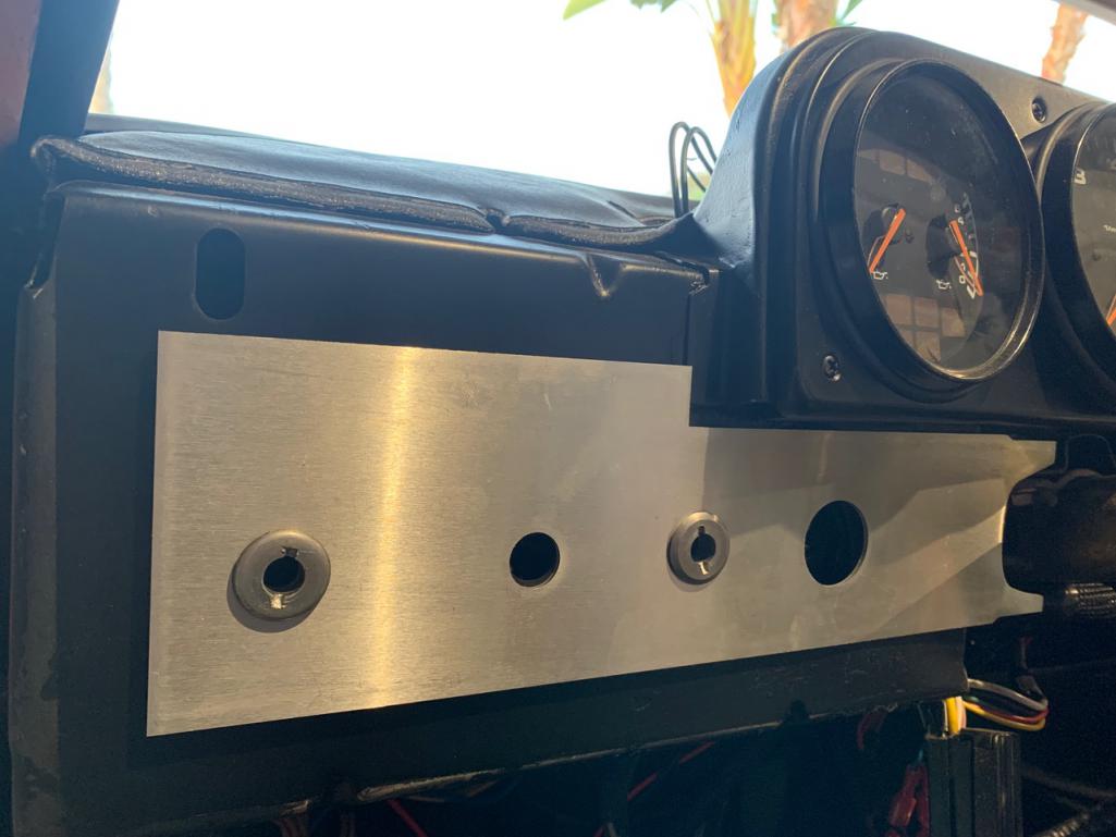 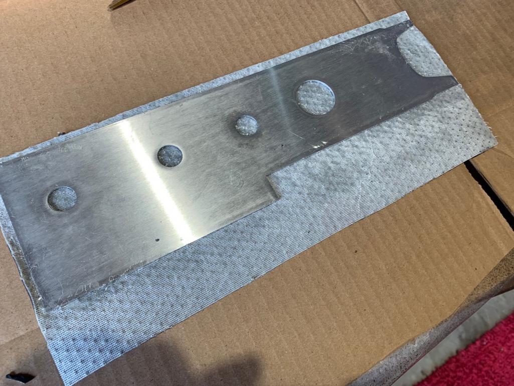 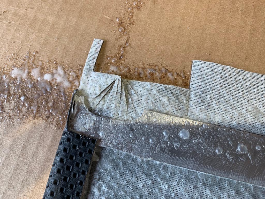 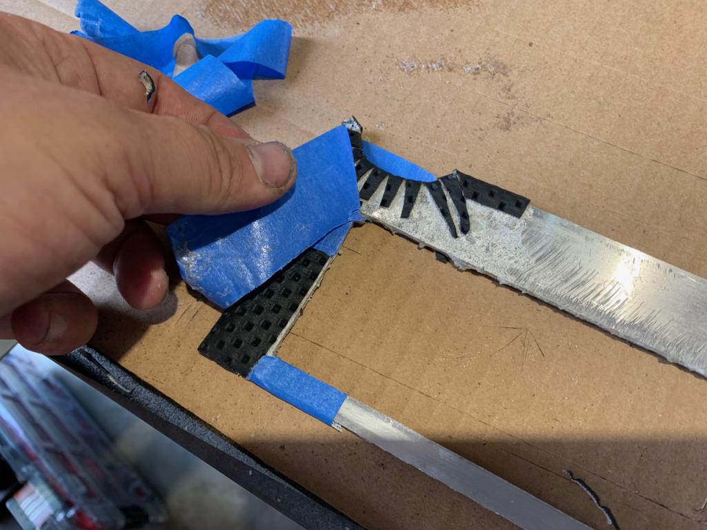 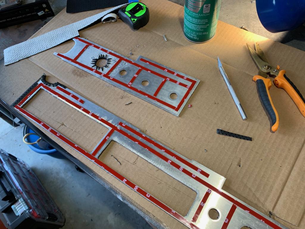 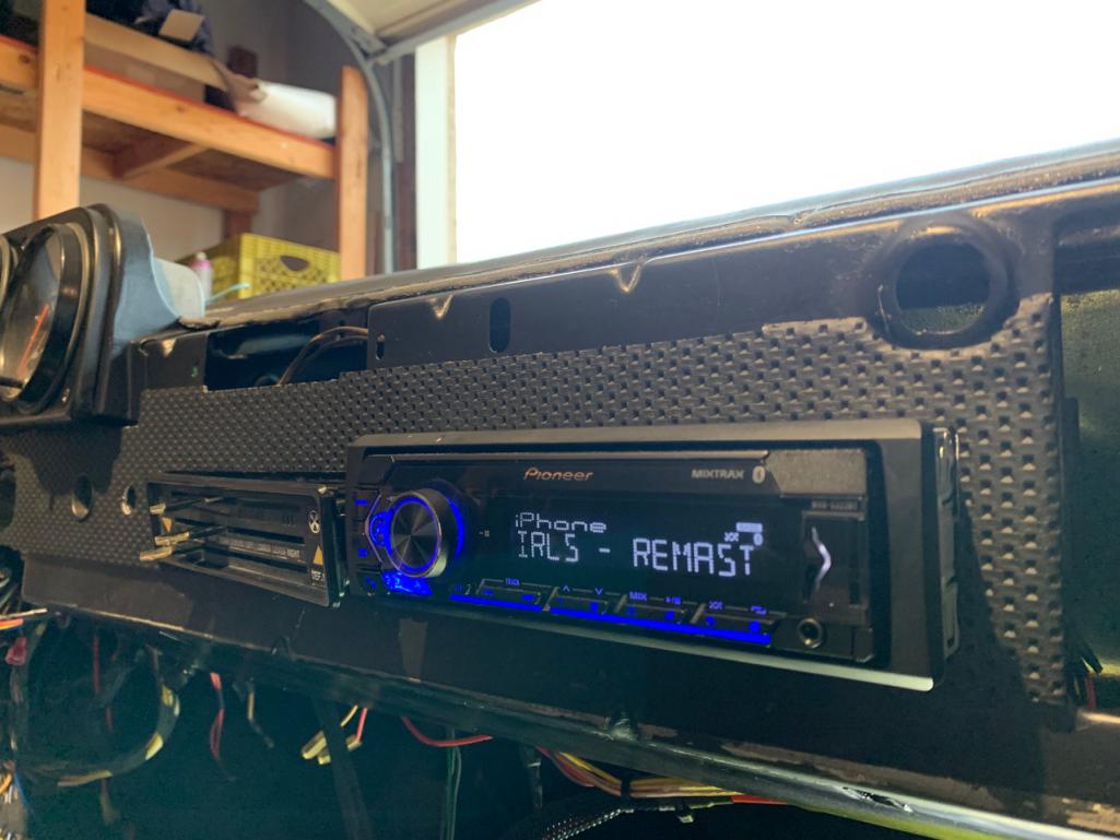 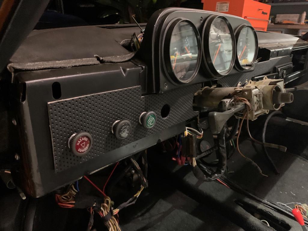 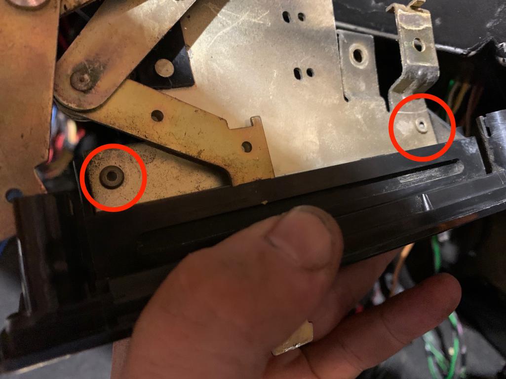 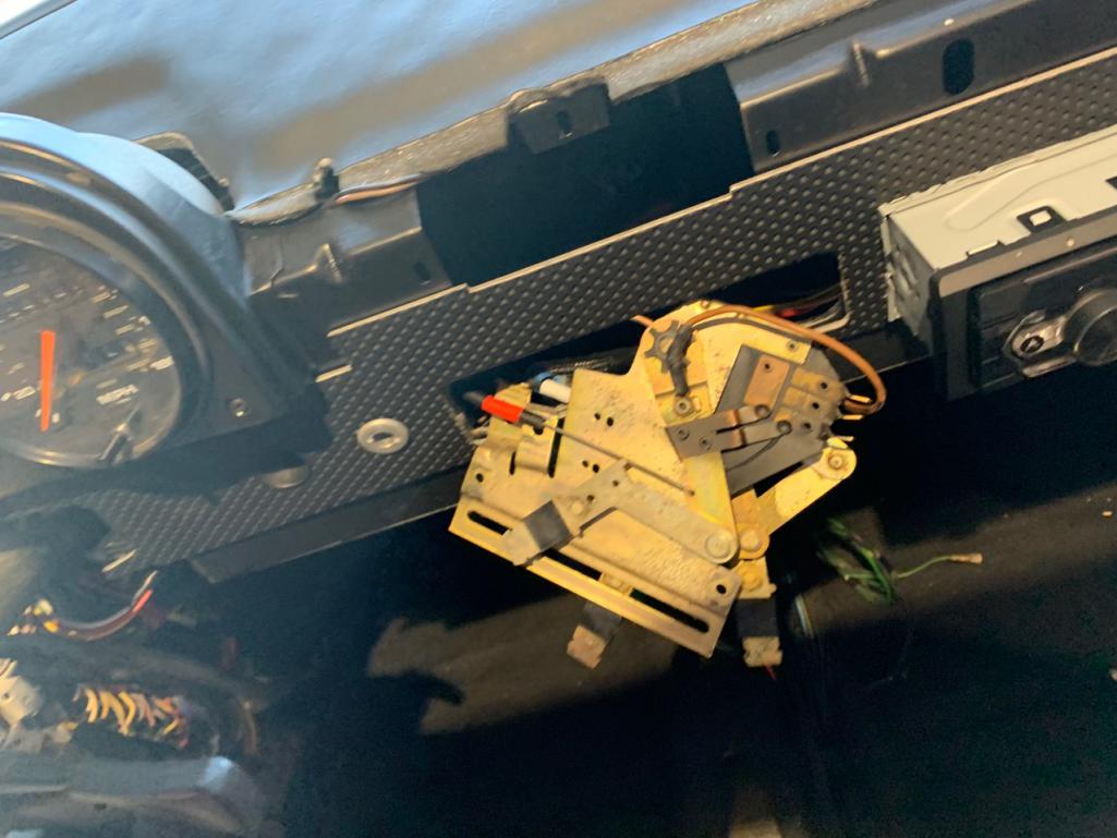 |
| Montreal914 |
 Sep 7 2021, 05:56 PM Sep 7 2021, 05:56 PM
Post
#996
|
|
Senior Member    Group: Members Posts: 1,800 Joined: 8-August 10 From: Claremont, CA Member No.: 12,023 Region Association: Southern California 
|
Very nice!
I assume if was for the radio installation that the cars came with a separate panel, but I always though the vinyl vertical joint line was “unfinished”. (IMG:style_emoticons/default/dry.gif) When I get to my dash, I will definitely do the vinyl one piece from steering to glove box like you did. (IMG:style_emoticons/default/smilie_pokal.gif) Please post a picture once everything is done. (IMG:style_emoticons/default/smile.gif) |
| RiqueMar |
 Sep 7 2021, 07:11 PM Sep 7 2021, 07:11 PM
Post
#997
|
|
Enrique Allen Mar     Group: Members Posts: 2,208 Joined: 28-August 08 From: San Diego, CA Member No.: 9,478 Region Association: Southern California 
|
Very nice! I assume if was for the radio installation that the cars came with a separate panel, but I always though the vinyl vertical joint line was “unfinished”. (IMG:style_emoticons/default/dry.gif) When I get to my dash, I will definitely do the vinyl one piece from steering to glove box like you did. (IMG:style_emoticons/default/smilie_pokal.gif) Please post a picture once everything is done. (IMG:style_emoticons/default/smile.gif) @Montreal914 - Same. For me once you see that line, you can't unsee it. Maybe I'm just too picky, but it looks weird. If you like, I think I have some prototype pieces. They may need some sanding or trimming (I remember the radio / heater control inlet was about 1/32" too small). Let me know if these would help. |
| Montreal914 |
 Sep 7 2021, 07:20 PM Sep 7 2021, 07:20 PM
Post
#998
|
|
Senior Member    Group: Members Posts: 1,800 Joined: 8-August 10 From: Claremont, CA Member No.: 12,023 Region Association: Southern California 
|
Very nice! I assume if was for the radio installation that the cars came with a separate panel, but I always though the vinyl vertical joint line was “unfinished”. (IMG:style_emoticons/default/dry.gif) When I get to my dash, I will definitely do the vinyl one piece from steering to glove box like you did. (IMG:style_emoticons/default/smilie_pokal.gif) Please post a picture once everything is done. (IMG:style_emoticons/default/smile.gif) @Montreal914 - Same. For me once you see that line, you can't unsee it. Maybe I'm just too picky, but it looks weird. If you like, I think I have some prototype pieces. They may need some sanding or trimming (I remember the radio / heater control inlet was about 1/32" too small). Let me know if these would help. Thank you for the offer. I am unfortunately far from getting into the dash in my rebuild project. Also I still haven’t decided what I will be doing for the radio. I am fully aware of your laser cutting and panel fabrication abilities. (IMG:style_emoticons/default/sunglasses.gif) Nice to see beautiful projects getting closer to the end. Thank you for sharing the process! (IMG:style_emoticons/default/smilie_pokal.gif) |
| Cairo94507 |
 Sep 8 2021, 07:31 AM Sep 8 2021, 07:31 AM
Post
#999
|
|
Michael           Group: Members Posts: 10,270 Joined: 1-November 08 From: Auburn, CA Member No.: 9,712 Region Association: Northern California 
|
@RiqueMar - Making nice progress brother. Thanks for the photo (IMG:style_emoticons/default/smile.gif)
|
| RiqueMar |
 Sep 8 2021, 11:16 PM Sep 8 2021, 11:16 PM
Post
#1000
|
|
Enrique Allen Mar     Group: Members Posts: 2,208 Joined: 28-August 08 From: San Diego, CA Member No.: 9,478 Region Association: Southern California 
|
Aaaaaaaaand my engine won't start now. Had it starting/reving/idling consistently while cleaning up the wiring. I think I must have connected something wrong, because over the weekend while testing gauges I noticed the DME and ECU were warm to the touch. Disconnecting the DME, believe I have a short somewhere in the system, because even when the DME relay is unplugged, I'm still getting voltage when touching various wires / connections
For now, I'm moving onto the more 'general' 914 things; Bleeding the Brakes, Accelerator/Clutch Cables, E-Brake, Shifter, etc. While I'm grateful to have learned so much so far, I don't want to dig in too much as I'm still very much a novice on the subject. For anyone following along, I've created the following diagram documenting my work so-far, I'm sure it's just a wire thats connected wrong or something, any input from the 'pro's' is appreciated. 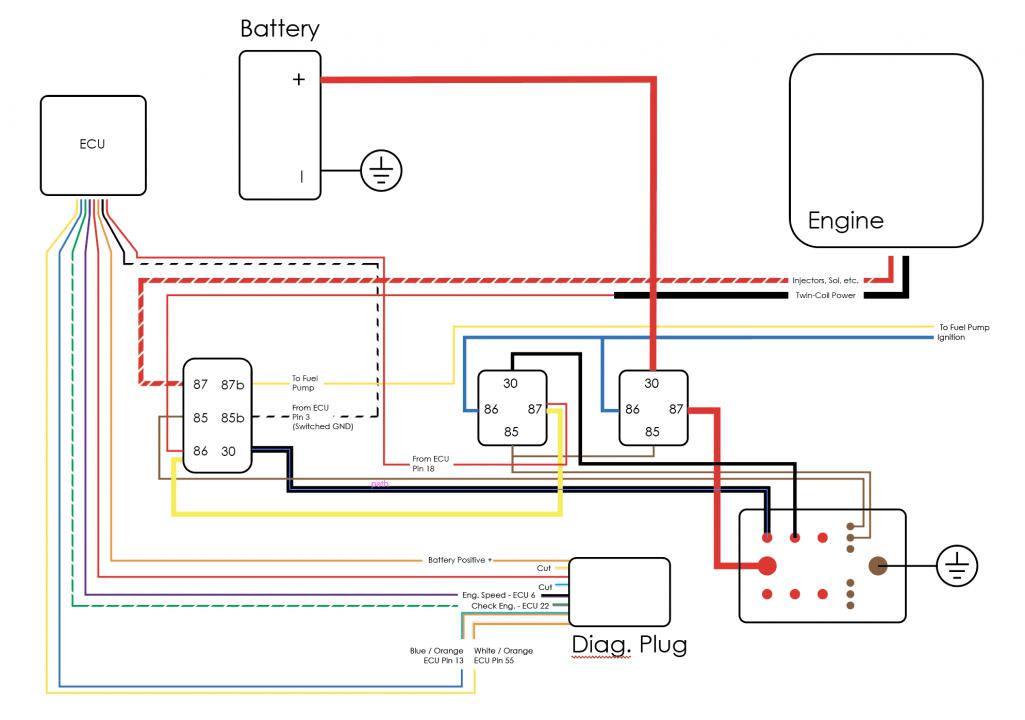 |
  |
2 User(s) are reading this topic (2 Guests and 0 Anonymous Users)
0 Members:

|
Lo-Fi Version | Time is now: 4th April 2025 - 05:26 AM |
Invision Power Board
v9.1.4 © 2025 IPS, Inc.


