|
|
|
Porsche, and the Porsche crest are registered trademarks of Dr. Ing. h.c. F. Porsche AG.
This site is not affiliated with Porsche in any way. Its only purpose is to provide an online forum for car enthusiasts. All other trademarks are property of their respective owners. |
|
|

  |

| McMark |
 Jun 13 2009, 07:23 PM Jun 13 2009, 07:23 PM
Post
#1
|
|
914 Freak!  Group: Retired Admin Posts: 20,179 Joined: 13-March 03 From: Grand Rapids, MI Member No.: 419 Region Association: None |
Since quite a few people were interested in crank fire and aftermarket FI system I finally finished up my crank position sensor setup. So if you want to run distributor-less ignition or modern FI, this setup is the ONLY setup built specifically to bolt onto a Type 4.
It's a complete bolt on upgrade, which means no drilling or modifying any parts to make this work. Only the cooling fan needs to be removed to complete the installation. This setup is great for modern FI system, which need a 'trigger signal'. Fuel only setups usually get their signal from the coil firing, but that signal is DIRTY and unreliable. This crank fire setup is smooth and clean. You can't beat it. There is no other setup built specifically for our motors. Quick easy installation with no headaches. Complete package price is $175 and includes the trigger wheel, the sensor, and the mounting bracket. You won't need to go searching for anything else. Attached image(s) 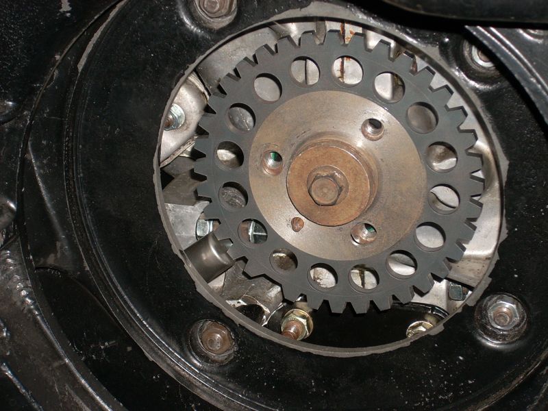
|
   |

 
|
| Gint |
Jun 13 2009, 07:25 PM
Post
#2
|
|
Mike Ginter Group: Admin Posts: 16,086 Joined: 26-December 02 From: Denver CO. Member No.: 20 Region Association: Rocky Mountains |
When I get to phaseII I'm in for one!
|
|
|
|
| Katmanken |
Jun 13 2009, 07:28 PM
Post
#3
|
|
You haven't seen me if anybody asks... Group: Members Posts: 4,738 Joined: 14-June 03 From: USA Member No.: 819 Region Association: Upper MidWest |
I nominate McMark for sainthood......
I propose that we al know him henceforth as Saint McMark of the position sensor and we all send him offerings of $175.00..... |
|
|
|
| hcdmueller |
Jun 13 2009, 08:30 PM
Post
#4
|
|
????????????? Group: Members Posts: 542 Joined: 4-February 06 From: UK Member No.: 5,527 Region Association: England |
Let me know how to pay and I will take one. I am collecting parts for my return later this year. This checks off several boxes.
|
|
|
|
| tat2dphreak |
Jun 13 2009, 08:37 PM
Post
#5
|
|
stoya, stoya, stoya Group: Benefactors Posts: 8,797 Joined: 6-June 03 From: Wylie, TX Member No.: 792 Region Association: Southwest Region |
when I start to do FI and ignoition, I'm totally IN this is a great deal, imo
|
|
|
|
| jhadler |
Jun 14 2009, 01:07 AM
Post
#6
|
|
Long term tinkerer... Group: Members Posts: 1,879 Joined: 7-April 03 From: Lyons, CO Member No.: 529 |
As soon as I can figure out if I can swing it, I'll be getting this. Even if I don't do EFI now, I won't have to pull the motor to do it later...
-Josh2 |
|
|
|
| CliffBraun |
Jun 14 2009, 02:04 AM
Post
#7
|
|
Member Group: Members Posts: 252 Joined: 26-April 06 From: San Luis Obispo,ca Member No.: 5,933 Region Association: None |
I have some questions, Looks really nice though.
Is it a hall effect sensor? if so, how do the sections removed for weight affect signal? Also, There seems to be a set of teeth with a way larger gap than the others. What's up with that? As I understand crank position you want to know at least two positions of the crank for a 4 cyl 4 stroke (two cyls fire/crank rotation) I might be wrong though. |
|
|
|
| jimkelly |
Jun 14 2009, 06:03 AM
Post
#8
|
|
Delaware USA Group: Members Posts: 4,969 Joined: 5-August 04 From: Delaware, USA Member No.: 2,460 Region Association: MidAtlantic Region |
i'm guessing that gap is TDC - top dead center.
jim |
|
|
|
| zymurgist |
Jun 14 2009, 06:58 AM
Post
#9
|
|
"Ace" Mechanic Group: Members Posts: 7,411 Joined: 9-June 05 From: Hagerstown, MD Member No.: 4,238 Region Association: None |
Sweet!
|
|
|
|
| ottox914 |
Jun 14 2009, 08:37 AM
Post
#10
|
|
The glory that once was. Group: Members Posts: 1,302 Joined: 15-December 03 From: Mahtomedi, MN Member No.: 1,438 Region Association: Upper MidWest |
QUOTE(CliffBraun @ Jun 14 2009, 12:04 AM)  I have some questions, Looks really nice though. Is it a hall effect sensor? if so, how do the sections removed for weight affect signal? Also, There seems to be a set of teeth with a way larger gap than the others. What's up with that? As I understand crank position you want to know at least two positions of the crank for a 4 cyl 4 stroke (two cyls fire/crank rotation) I might be wrong though. Look closely and see that there are 35 teeth, one missing. 360 degrees is a circle. The "missing tooth" is now a reference point for TDC. The programing of the SDS requires a different sensor set up, so this new system may not be of much help for that ECU, but for those looking to do MS, this is the right tool for the job, priced right, easy to install. Great job. |
|
|
|
| DNHunt |
Jun 14 2009, 08:55 AM
Post
#11
|
|
914 Wizard? No way. I got too much to learn. Group: Members Posts: 4,099 Joined: 21-April 03 From: Gig Harbor, WA Member No.: 598 |
Really nice Mark. Simple.
|
|
|
|
| toon1 |
Jun 14 2009, 08:56 AM
Post
#12
|
|
Senior Member Group: Members Posts: 1,849 Joined: 29-October 05 From: tracy,ca Member No.: 5,022 |
Looks good Mark. Do you have pics. of how the sensor mounts to the case?
|
|
|
|
| Spoke |
Jun 14 2009, 09:01 AM
Post
#13
|
|
Jerry Group: Members Posts: 6,996 Joined: 29-October 04 From: Allentown, PA Member No.: 3,031 Region Association: None |
Really cool! The Type IV moving into the 21st century.
A question though and probably shows my lack of knowledge on the subject, I remember on my Subaru having to change not only the crank angle sensor but also the cam angle sensor. With TDC of the crank being for 2 of the cylinders, how do you know which cylinder to fire? When I was prepping the engine for my red 914, I couldn't tell if I had the dizzy pointing to the right cylinder w/o removing a valve cover to check for TDC of cylinder 1. |
|
|
|
| DNHunt |
Jun 14 2009, 09:15 AM
Post
#14
|
|
914 Wizard? No way. I got too much to learn. Group: Members Posts: 4,099 Joined: 21-April 03 From: Gig Harbor, WA Member No.: 598 |
Jerry
The system is batch fire Fuel and wasted spark ignition. The spark fires in 1&3 together and 2&4 together so it always fires 2 plugs. It will fire a pair of cylinders near TDC on the compression stroke in one and near TDC on the exhaust stroke in the other. Because the exhaust gasis a poor conductor very little spark energy is used and that little bit is wasted hence the name. It eliminates the need for a cam sensor. I suppose you could say it is not state of the art but it is pretty simple and doesn't give up much to very elaborate systems that use a cam sensor to control each cylinder on its own. Dave |
|
|
|
| toon1 |
Jun 14 2009, 09:17 AM
Post
#15
|
|
Senior Member Group: Members Posts: 1,849 Joined: 29-October 05 From: tracy,ca Member No.: 5,022 |
With the 36-1 trigger wheel, the missing tooth indicates TDC. Tooth #10( in this case)indicates10* BTDC and fires cyl.#1
When mounting the trigger wheel, the engine must be brought to TDC.(just like installing a dizzy.) It does not matter where the sensor is mounted Or where the missing tooth is placed, as long as the sensor points to a certain tooth on the wheel( #10 I think) form the missing tooth in the rotation of the engine When you configure the programming in the software there is a decoder program which is configured for a 4 cyl.(simple to do) Everytime the sensor senses the missing tooth the computer know to start a new cycle. I have my sensor mounted to the fan shroud at about the 10 o clock posistion where Mark has his at about 8 o clock |
|
|
|
| CliffBraun |
Jun 14 2009, 12:49 PM
Post
#16
|
|
Member Group: Members Posts: 252 Joined: 26-April 06 From: San Luis Obispo,ca Member No.: 5,933 Region Association: None |
QUOTE(toon1 @ Jun 14 2009, 08:17 AM) With the 36-1 trigger wheel, the missing tooth indicates TDC. Tooth #10( in this case)indicates10* BTDC and fires cyl.#1 When mounting the trigger wheel, the engine must be brought to TDC.(just like installing a dizzy.) It does not matter where the sensor is mounted Or where the missing tooth is placed, as long as the sensor points to a certain tooth on the wheel( #10 I think) form the missing tooth in the rotation of the engine When you configure the programming in the software there is a decoder program which is configured for a 4 cyl.(simple to do) Everytime the sensor senses the missing tooth the computer know to start a new cycle. I have my sensor mounted to the fan shroud at about the 10 o clock posistion where Mark has his at about 8 o clock Thanks, Nice product. Has anyone figured out a good way to do a cam sensor? |
|
|
|
| 904svo |
Jun 14 2009, 12:56 PM
Post
#17
|
|
904SVO Group: Members Posts: 1,119 Joined: 17-November 05 From: Woodstock,Georgia Member No.: 5,146 |
QUOTE(CliffBraun @ Jun 14 2009, 10:49 AM) QUOTE(toon1 @ Jun 14 2009, 08:17 AM) With the 36-1 trigger wheel, the missing tooth indicates TDC. Tooth #10( in this case)indicates10* BTDC and fires cyl.#1 When mounting the trigger wheel, the engine must be brought to TDC.(just like installing a dizzy.) It does not matter where the sensor is mounted Or where the missing tooth is placed, as long as the sensor points to a certain tooth on the wheel( #10 I think) form the missing tooth in the rotation of the engine When you configure the programming in the software there is a decoder program which is configured for a 4 cyl.(simple to do) Everytime the sensor senses the missing tooth the computer know to start a new cycle. I have my sensor mounted to the fan shroud at about the 10 o clock position where Mark has his at about 8 o clock Thanks, Nice product. Has anyone figured out a good way to do a cam sensor? Modify the distrubutor for cam position sensor, thats what Ford did. |
|
|
|
| McMark |
Jun 14 2009, 01:38 PM
Post
#18
|
|
914 Freak! Group: Retired Admin Posts: 20,179 Joined: 13-March 03 From: Grand Rapids, MI Member No.: 419 Region Association: None |
Why would you want a cam sensor? You will find no appreciable benefit to going with sequential injection, so you're talking about adding complexity for zero benefit. (IMG:style_emoticons/default/confused24.gif)
QUOTE With TDC of the crank being for 2 of the cylinders, how do you know which cylinder to fire? As Dave mentioned, batch fire injectors and wasted spark systems fire fuel and/or spark every crank revolution. That's why it's called wasted spark, one of the spark events is worthless. This is an absolutely common way to run your fuel injection. It makes things much much more simple and has no real benefit on anything less than a 'bleeding edge' motor.This system uses a VR sensor, not a Hall Sensor. SDS requires the use of a Hall Sensor, so this system will not work with SDS. Here is a detail of the sensor mount. Attached image(s) 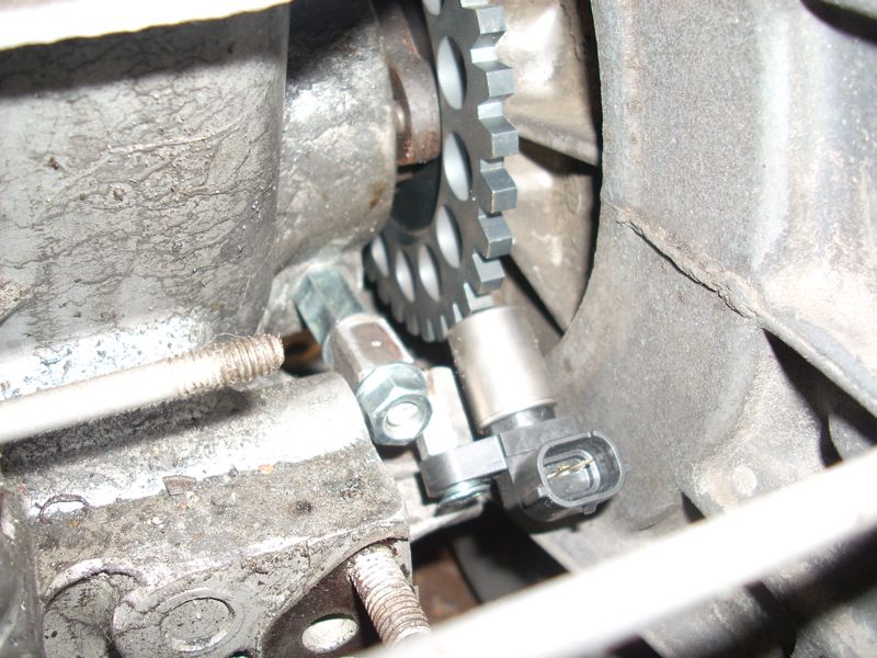
|
|
|
|
| Jacob |
Jun 14 2009, 02:12 PM
Post
#19
|
|
Member Group: Members Posts: 131 Joined: 12-February 08 From: Mansfield, Oh Member No.: 8,705 Region Association: Upper MidWest |
Looks like the center hub is about the same thickness as the stock washer, right? That is great! That means you are not adversely affecting you cooling system. How is the toothed ring affixed to the hub. Press fit? Welded?
Looks like great workmanship. |
|
|
|
| McMark |
Jun 14 2009, 02:25 PM
Post
#20
|
|
914 Freak! Group: Retired Admin Posts: 20,179 Joined: 13-March 03 From: Grand Rapids, MI Member No.: 419 Region Association: None |
The toothed wheel replaces the stock 'washer' and installs in the same manner. The toothed wheel is 'sandwiched' between the hub and the fan, just like the stock piece.
|
|
|
|
|
1 User(s) are reading this topic (1 Guests and 0 Anonymous Users)
0 Members:

|
Lo-Fi Version | Time is now: 28th June 2024 - 03:14 PM |
Invision Power Board
v9.1.4 © 2024 IPS, Inc.