|
|
FRONT SWAY BAR INSTALL
by Orange914
Ever wondered how much effort and time it would take to put in a front sway bar? It's really
not bad and SO worth the effort!
This covers the install from beginning to end with lots of pictures.
You can easily do it in a weekend or less, it requires r&r of the fuel tank and front wheels,
a drill and uni-bit, basic hand tools/jack stands, die grinder cut off wheel and of course the complete sway
bar set. (I've heard not all 914's don't have the u-bracket on the lower control arm and this will require
welding (one on each side)
TOOLS & SUPPLIES
- Sway bar/end links/all grade 5+ bolts/hardware
- Jack & stands
- Tire iron
- 3/8" drill
- Unibit or hole saw and drill bit set
- Bocket set & ratchet
- Box end wrench set
- Marker pen (for marking pattern to drill)
- Die grinder & cut off wheel
- Wheel bearing grease (for bushings)
- Welder & *u-brackets (ONLY if u-brackets NOT factory installed on lower arms - check
before starting project)
Step 1: PREPARING vehicle
- Plan your gas to be at the lowest level to facilitate fuel tank removal
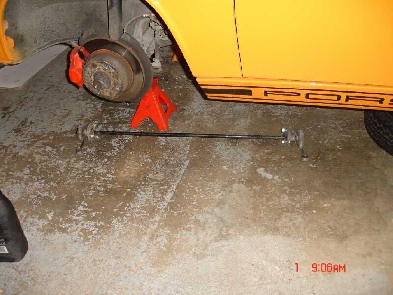
- Put front end up and remove rims
- Lay out sway bar end links all bushing, brackets, bolts and inventory
- Have drill & uni-bit Along with basic hand tools set aside and ready
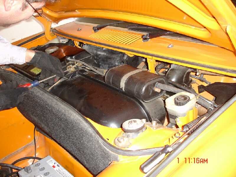
Step 2: REMOVE tank
- Unbolt upper fill tank/remove, unbolt tank strap, lift out of way and remove tank blocks
- Lift (preferably empty) fuel tank to stopping point. The fuel lines will give resistance
and limited lift. The easiest way is just cut existing fuel lines(old/dry/cracked and brittle anyway). Be
careful to pay attention to proper line routing as reversed hook up WILL cause damage.
- Place out of the way
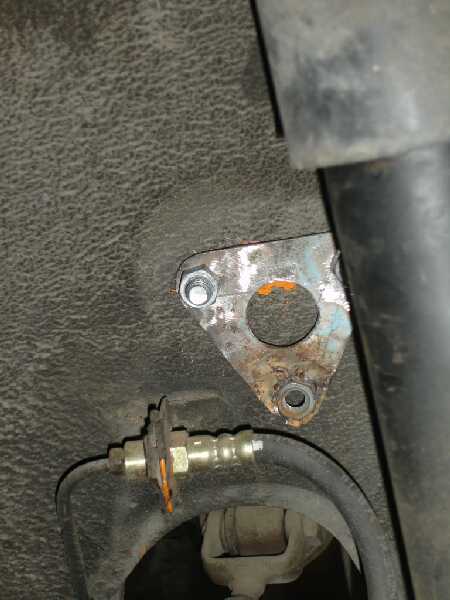
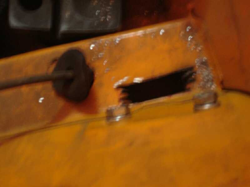
Step 3: MARK AND DRILL template for bar clamp brackets
- Look for factory raised area at inner wheel well
- Use sway bar bracket for hole template, center in boss area and scribe or mark for
drilling
- Drill top hole, hang and check alignment of other marks
- Drill remaining holes
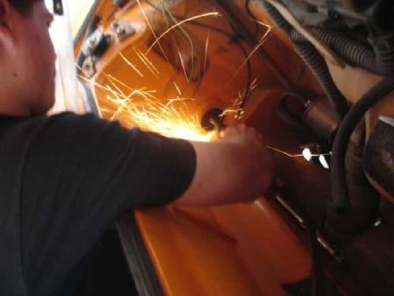
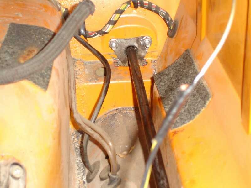
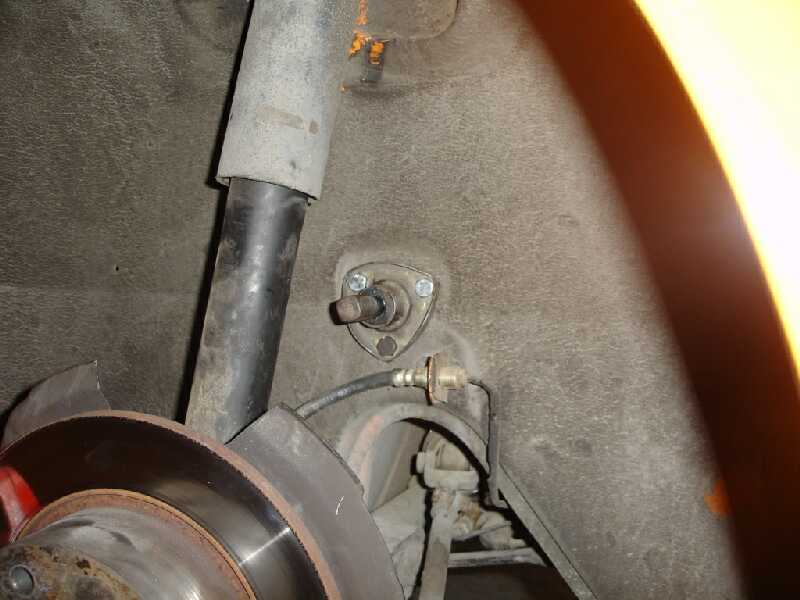
Step 4: INSTALL INNER bar, BRACKETS and ARMS
- Cut away apx. A 3/4" x 3" groove to facilitate inner bracket
- Slip in bar through holes and inner brackets, grease and install bushings, brackets and
retaianing bolts
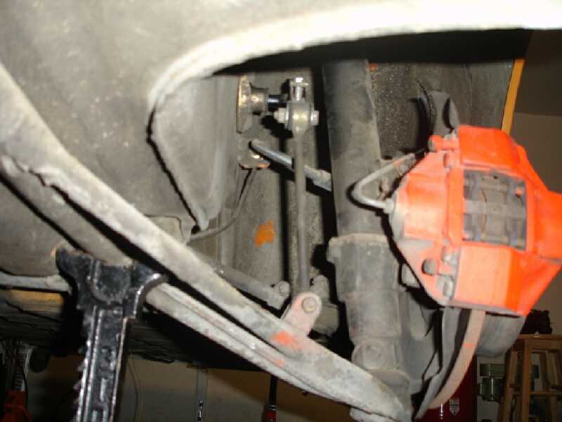
- Clamp on arms and end links, attach to lower control arm u-bracket (you may have not
factory brackets and have to fabricate/weld new to the lower arms)
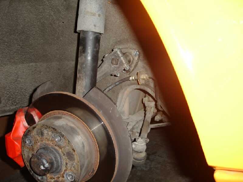
Step 5: RE-INSTALL FUEL TANK and RIMS, TEST DRIVE and ENJOY
|
|