|
|

|
Porsche, and the Porsche crest are registered trademarks of Dr. Ing. h.c. F. Porsche AG.
This site is not affiliated with Porsche in any way. Its only purpose is to provide an online forum for car enthusiasts. All other trademarks are property of their respective owners. |
|
|
| Steve_R |
 Jul 6 2015, 05:28 PM Jul 6 2015, 05:28 PM
Post
#1
|
|
Member   Group: Members Posts: 68 Joined: 8-August 12 From: San Diego, CA Member No.: 14,777 Region Association: None |
Well, it’s been about a year since I finished my 914 restoration, you can read all about it
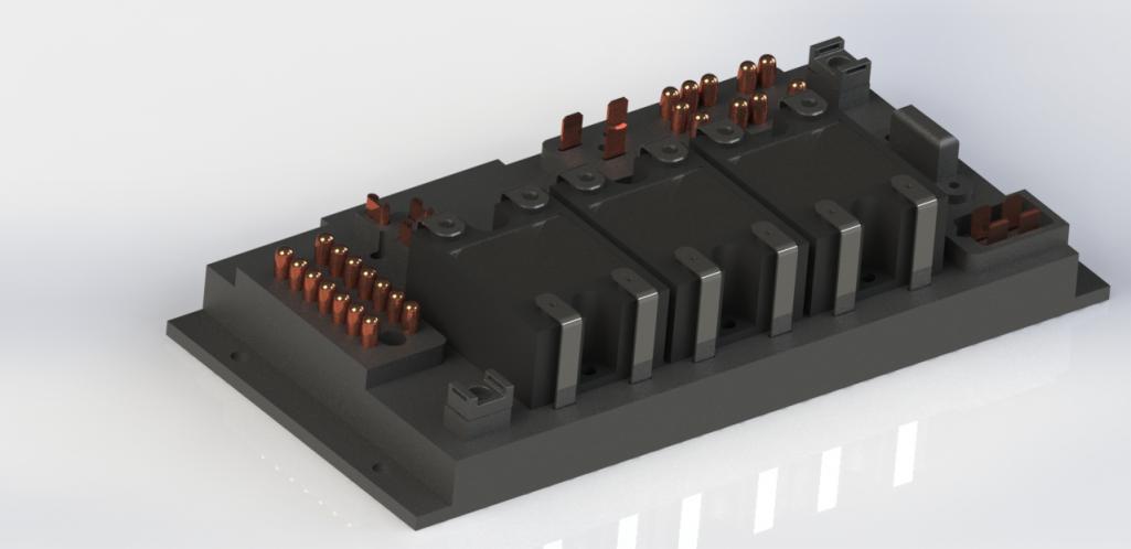
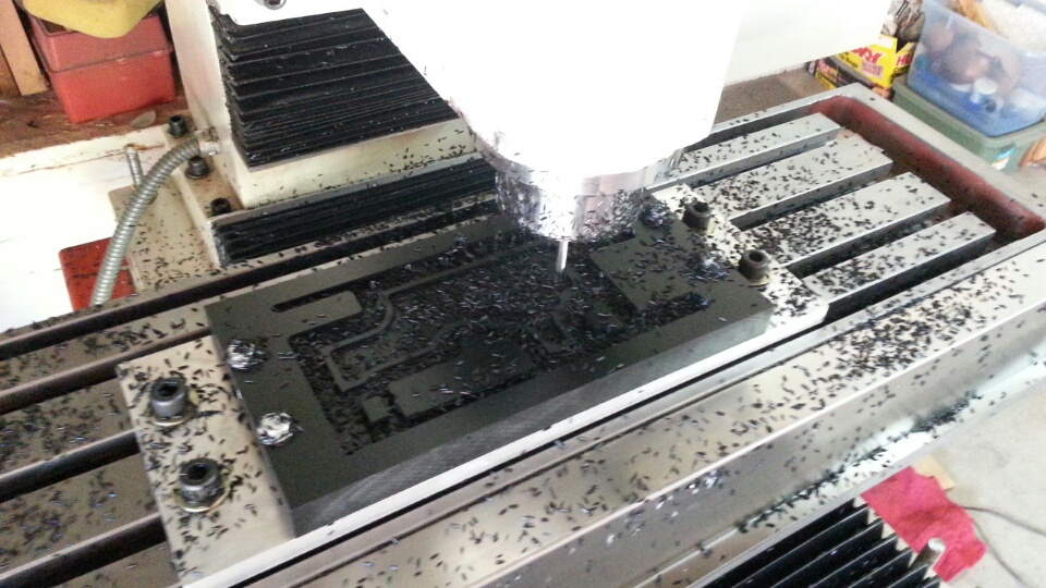
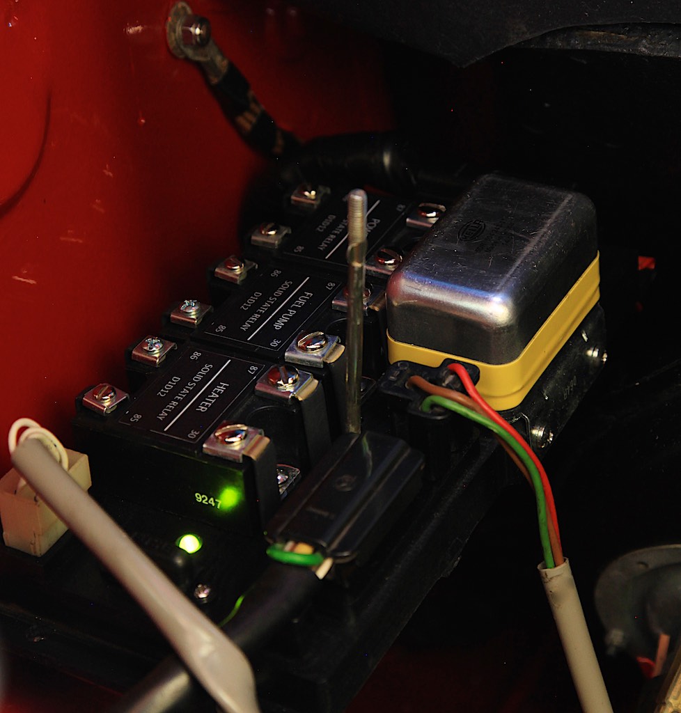
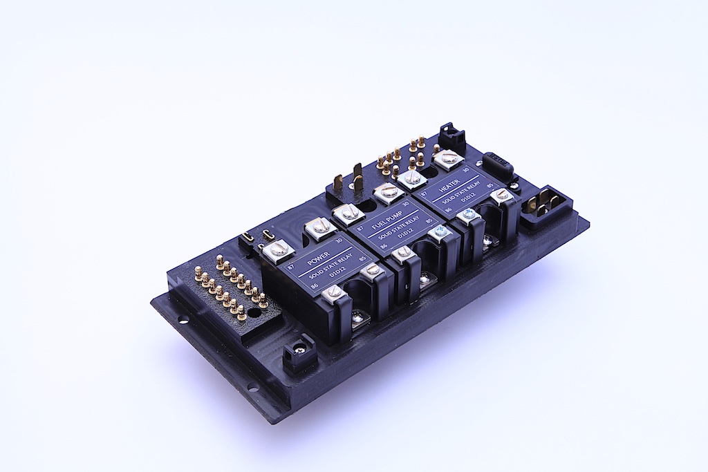
HERE. Everything works perfect except for the electrical problems I’ve been having with the relay board. I spent lots of hours trouble shooting electrical issues with the fuel pump. It turs out that my relay board had some bad connections for the fuel pump relay. After searching this site I discovered that the relay board is truly the weakest link in the 914. I tried to remove the epoxy bedding underneath the board and resolder the connections. This worked for a while but the fuel pump would sometimes stop and kill the engine. I finally figured out that the contacts for the fuel pump relay to the board were causing the problem. This seems like a never ending problem. I could buy another 40 year old used board and have the same problems. So, to make a long story short, I decided to design a new relay board from scratch. I replaced the original electromechanical relays with industrial solid state relays. They have the same connection labels as the stock relays: 85 & 86 for the coil and 30 & 87 for the switch. The relays are available at most electrical parts dealers like Mouser or Digi-Key if one ever needs to be replace. They also use a lot less power than the original 914 relays. Also, since they are solid state and don’t have any moving parts they will last a lot longer and are more reliable. I also replaced the old ceramic fuse with a modern ATC style fuse and added an LED that illuminates when the fuel pump has power. This is great for trouble shooting fuel pump issues. It comes on for a few seconds after the key is turned on and stays on when the engine is running. Also, I removed the connections and plug for the rear window defroster. I used wires soldered to the connectors eliminating all of the riveted connections. All connections are soldered. To make the board I CNC machined the board out of high density polyethylene plastic. I built a few extra boards to offset some of the development costs. They are quite labor extensive to build so I don’t plan to mass produce them. PM me if you want one. I would like to get $500.00 each. That includes the board with the solid stare relays. It does not include the voltage regulator. I used a solid state one from Pelican Parts. Both the stock and solid state voltage regulators will work. Attached thumbnail(s)  Attached image(s)   
|
  |
Replies
| JeffBowlsby |
 Jul 22 2015, 01:41 PM Jul 22 2015, 01:41 PM
Post
#2
|
|
914 Wiring Harnesses      Group: Members Posts: 8,788 Joined: 7-January 03 From: San Ramon CA Member No.: 104 Region Association: None 
|
Drooling over this, I have some observations and questions:
* This board would not work for 914s with a rear window defroster * This board would not work for the 1972-only 914s that use pin 3 of the 12-pin connector for an oil temp sender circuit (to the dash gauge) * Why the difference in the slotted/Phillips screws on the corners of each relay? Are those screws are ready power sources in the engine bay? * Would you consider making a kit with just the base and parts list/instructions available? |
| Steve_R |
 Jul 22 2015, 06:37 PM Jul 22 2015, 06:37 PM
Post
#3
|
|
Member   Group: Members Posts: 68 Joined: 8-August 12 From: San Diego, CA Member No.: 14,777 Region Association: None |
Drooling over this, I have some observations and questions: * This board would not work for 914s with a rear window defroster * This board would not work for the 1972-only 914s that use pin 3 of the 12-pin connector for an oil temp sender circuit (to the dash gauge) * Why the difference in the slotted/Phillips screws on the corners of each relay? Are those screws are ready power sources in the engine bay? * Would you consider making a kit with just the base and parts list/instructions available? Hi Jeff, * This board would not work for 914s with a rear window defroster .Yep, there was only enough room for 3 solid state relays. I read somewhere that only about 5% of 914 have a rear window defroster. Is this true? * This board would not work for the 1972-only 914s that use pin 3 of the 12-pin connector for an oil temp sender circuit (to the dash gauge) Good point. My car is a 1973 and I didn't notice that there is a difference. Are there any other differences between years for the relay boards? * Why the difference in the slotted/Phillips screws on the corners of each relay? Are those screws are ready power sources in the engine bay? . No reason. one of the relays I got had different fasteners. * Would you consider making a kit with just the base and parts list/instructions available? Maybe in the future. Right now I am working on another project. |
| JeffBowlsby |
 Jul 22 2015, 08:37 PM Jul 22 2015, 08:37 PM
Post
#4
|
|
914 Wiring Harnesses      Group: Members Posts: 8,788 Joined: 7-January 03 From: San Ramon CA Member No.: 104 Region Association: None 
|
Drooling over this, I have some observations and questions: * This board would not work for 914s with a rear window defroster * This board would not work for the 1972-only 914s that use pin 3 of the 12-pin connector for an oil temp sender circuit (to the dash gauge) * Why the difference in the slotted/Phillips screws on the corners of each relay? Are those screws are ready power sources in the engine bay? * Would you consider making a kit with just the base and parts list/instructions available? Hi Jeff, * This board would not work for 914s with a rear window defroster .Yep, there was only enough room for 3 solid state relays. I read somewhere that only about 5% of 914 have a rear window defroster. Is this true? * This board would not work for the 1972-only 914s that use pin 3 of the 12-pin connector for an oil temp sender circuit (to the dash gauge) Good point. My car is a 1973 and I didn't notice that there is a difference. Are there any other differenced between years for the relay boards? * Why the difference in the slotted/Phillips screws on the corners of each relay? Are those screws are ready power sources in the engine bay? . No reason. one of the relays I got had different fasteners. * Would you consider making a kit with just the base and parts list/instructions available? Maybe in the future. Right now I am working on another project. Your work is commendable Steve, I hope you can find a way to make these available to the masses. I understand that the 914 was one of the first if not the first vehicle to use a configured board like this and a modern replacement using current technology would be welcomed. If a kit was available, there are enough DIY types here that mounting the relays and wiring it up would be one way to minimize the investment. Maybe a group buy in quantity as well. Mark Whitesell may be interested in producing them with your assistance, especially if they can be molded or done in a production mode. "Mikey914" The 914/4 boards were all the same, but the three harnesses that plug into them were different. The 1972-only ignition harness is the only one that uses pin 3 of the 12-pin, I don't recall if the chassis harnesses interface with the board differently, would need to research it. The /6 guys need their version just as much as the /4 guys do. |
| Steve_R |
 Jul 22 2015, 09:35 PM Jul 22 2015, 09:35 PM
Post
#5
|
|
Member   Group: Members Posts: 68 Joined: 8-August 12 From: San Diego, CA Member No.: 14,777 Region Association: None |
Drooling over this, I have some observations and questions: * This board would not work for 914s with a rear window defroster * This board would not work for the 1972-only 914s that use pin 3 of the 12-pin connector for an oil temp sender circuit (to the dash gauge) * Why the difference in the slotted/Phillips screws on the corners of each relay? Are those screws are ready power sources in the engine bay? * Would you consider making a kit with just the base and parts list/instructions available? Hi Jeff, * This board would not work for 914s with a rear window defroster .Yep, there was only enough room for 3 solid state relays. I read somewhere that only about 5% of 914 have a rear window defroster. Is this true? * This board would not work for the 1972-only 914s that use pin 3 of the 12-pin connector for an oil temp sender circuit (to the dash gauge) Good point. My car is a 1973 and I didn't notice that there is a difference. Are there any other differenced between years for the relay boards? * Why the difference in the slotted/Phillips screws on the corners of each relay? Are those screws are ready power sources in the engine bay? . No reason. one of the relays I got had different fasteners. * Would you consider making a kit with just the base and parts list/instructions available? Maybe in the future. Right now I am working on another project. Your work is commendable Steve, I hope you can find a way to make these available to the masses. I understand that the 914 was one of the first if not the first vehicle to use a configured board like this and a modern replacement using current technology would be welcomed. If a kit was available, there are enough DIY types here that mounting the relays and wiring it up would be one way to minimize the investment. Maybe a group buy in quantity as well. Mark Whitesell may be interested in producing them with your assistance, especially if they can be molded or done in a production mode. "Mikey914" The 914/4 boards were all the same, but the three harnesses that plug into them were different. The 1972-only ignition harness is the only one that uses pin 3 of the 12-pin, I don't recall if the chassis harnesses interface with the board differently, would need to research it. The /6 guys need their version just as much as the /4 guys do. Thanks Jeff. I already spoke to mark about these. Unfortunately, when I designed this board I was not thinking about mass producing them. I have a good day job. I really just planned to make one and a couple extra to sell to help pay for some of the tools I needed. The board itself is machined from plastic using a CNC mill that uses 10 different tools (end mills and drills) and takes 3 hours to machine. My mill does not have an automatic tool changer so I need to be near the mill for the 3 hours. Also, the relays are industrial quality that are used in robots and medical equipment so they're not cheep. However, I think it could be redesigned to be machined on a CNC router with one tool and use automotive solid state relays. Right now I just have too much on my plate. |
Posts in this topic
 Steve_R Solid State Relay Board Jul 6 2015, 05:28 PM
 Jeff Bowlsby Wow... Jul 6 2015, 05:35 PM
 steuspeed :agree: :shades2: Jul 6 2015, 05:44 PM
 SirAndy :trophy:
Very nice!
Just a FYI, i was able t... Jul 6 2015, 05:47 PM
 jim_hoyland Thanks for posting; I saw your car at the PCA Conc... Jul 6 2015, 05:59 PM
 McMark Really cool! :thumbsup:
What's the back ... Jul 6 2015, 06:00 PM

 Steve_R
Really cool! :thumbsup:
What's the back... Jul 7 2015, 06:55 AM

 McMark
Really cool! :thumbsup:
What's the bac... Jul 7 2015, 10:26 PM

 Mueller
[quote name='Steve_R' post='2207091' date='Jul 7 ... Jul 7 2015, 10:51 PM


 SirAndy What is the diameter of the stock round units? The... Jul 8 2015, 05:36 PM

 N_Jay
Wasn't planning on it. I'm a bit of a nu... Sep 21 2016, 07:06 AM
 Harpo Very impressive. You have some skills there.
Dav... Jul 6 2015, 06:04 PM
 Mike Bellis I like it!
I'm running solid state relays... Jul 6 2015, 06:09 PM
 Mblizzard Holy crap that is cool!
Wish I had the cash a... Jul 6 2015, 07:08 PM
 somd914 :drooley: :drooley: :drooley:
Very nice work. ... Jul 6 2015, 07:12 PM
 saigon71 Very impressive - nice work! :beer2: Jul 6 2015, 08:15 PM
 914Sixer Am I missing it or is there no plug for the heated... Jul 7 2015, 08:47 AM

 Steve_R
Am I missing it or is there no plug for the heate... Jul 7 2015, 07:47 PM
 Mueller Damn...that is a nice assembly....Tormach mill? Jul 7 2015, 09:40 AM
 thieuster I take my hat off, sir! Amazing stuff!
M... Jul 7 2015, 09:47 AM
 clapeza Doesn't this belong in the Sandbox?
...becaus... Jul 7 2015, 12:07 PM
 Maltese Falcon +1
First Class product Jul 8 2015, 12:20 AM
 GregAmy I'm gonna sound redundant but...that's som... Jul 8 2015, 06:22 AM
 Cairo94507 :woohoo: :trophy: That is some very nice work the... Jul 8 2015, 06:56 AM
 02loftsmoor
Well, it’s been about a year since I finished m... Jul 8 2015, 08:49 AM

 Mueller
r
Question for you Looks like they are. Are the... Jul 8 2015, 01:35 PM

 Steve_R
[quote name='Steve_R' post='2206828' date='Jul 6 ... Jul 8 2015, 04:01 PM

 Mueller
 is correct, these are not serviceable. N... Jul 8 2015, 06:12 PM
Mueller
Mueller is correct, these are not serviceable. N... Jul 8 2015, 06:12 PM

 Steve_R
Mueller is correct, these are not serviceable. ... Jul 8 2015, 06:31 PM
 jfort Very cool. Nice work. I assume it won't work o... Jul 8 2015, 09:26 AM
 pete000 Nice blend of modern technology ! Jul 8 2015, 02:01 PM
 dangerranger01 I like this a lot. Did you do your own pcb, or how... Jul 8 2015, 04:57 PM

 Steve_R
I like this a lot. Did you do your own pcb, or ho... Jul 8 2015, 05:40 PM
 mr914 :agree:
Impressive, got to be in the hundreds of ... Jul 8 2015, 05:09 PM
 Geezer914 That is a work of art worthy of being framed and h... Jul 8 2015, 05:27 PM
 jwc914 This will go very well with my 160 amp alt kit. It... Jul 11 2015, 02:22 PM

 Steve_R
This will go very well with my 160 amp alt kit. I... Jul 11 2015, 05:17 PM
 02loftsmoor I would like to get with on the relay board. Wes Jul 11 2015, 11:01 PM
 Cairo94507 I wish you made one of those boards for the Sixes.... Jul 12 2015, 07:12 AM
 Kalani
Well, it’s been about a year since I finished m... Jul 13 2015, 10:08 PM
 Kalani Hello Steve,
Do you have any left, and has the p... Jul 13 2015, 10:10 PM

 Steve_R
Hello Steve,
Do you have any left, and has the ... Jul 13 2015, 11:18 PM
 Zimms These are beautiful! Worth every cent.
Jul 15 2015, 10:09 AM

 jd74914
However, I think it could be redesigned to be mac... Jul 22 2015, 09:43 PM

 Steve_R
[quote name='Steve_R' post='2213744' date='Jul 22... Jul 22 2015, 09:58 PM
 Strudelwagon we use these at work... Apr 7 2016, 10:50 PM
 cegallegos99 Any good relay boards for sale?
I am asking since... Apr 17 2016, 09:45 PM

 RoadGlue
Any good relay boards for sale?
I am asking sinc... Apr 18 2016, 04:45 PM
 Cairo94507 Man, do I wish Steve would make these for a Six...... Sep 21 2016, 07:12 AM
 N_Jay So close, but so far.
I certainly understand why ... Sep 21 2016, 07:24 AM

 Whitney Mic
So close, but so far.
I certainly understand why... Sep 21 2016, 06:49 PM
 N_Jay If I can get the pins for the body and engine conn... Sep 21 2016, 08:15 PM
 NS914 Hi Steve,
Your relay board is truly a work of art... Sep 23 2016, 07:47 AM
 cegallegos99 Hi
I am looking at yours as a new production
Do ... Jan 14 2017, 11:48 PM
 Mueller Steve,
If you decide to out source the machining... May 16 2017, 11:59 AM
 Mikey914 We've been spending some time putting together... May 16 2017, 02:00 PM

 peteyd
We've been spending some time putting togethe... Apr 3 2020, 02:38 PM

 Mikey914
[quote name='Mikey914' post='2486779' date='May 1... Apr 3 2020, 07:19 PM

 Spoke
Actually we are working on the board. We decided ... Apr 3 2020, 08:24 PM

 peteyd
[quote name='Mikey914' post='2486779' date='May ... Apr 6 2020, 06:04 AM
 mbseto I'd volunteer to create an STL file (i.e. a fi... Apr 3 2020, 03:45 PM
 Spoke What needs to be done on this? Looks like it would... Apr 3 2020, 05:20 PM
 Mikey914 Size is really the issue. They are relitively inex... Apr 3 2020, 08:54 PM
 GregAmy I suggest that one of the biggest failures on thes... Apr 3 2020, 09:03 PM
 Mikey914 That's where we are going with this. Apr 3 2020, 09:15 PM
  |
38 User(s) are reading this topic (38 Guests and 0 Anonymous Users)
0 Members:

|
Lo-Fi Version | Time is now: 8th January 2025 - 12:34 AM |
Invision Power Board
v9.1.4 © 2025 IPS, Inc.


