|
|

|
Porsche, and the Porsche crest are registered trademarks of Dr. Ing. h.c. F. Porsche AG.
This site is not affiliated with Porsche in any way. Its only purpose is to provide an online forum for car enthusiasts. All other trademarks are property of their respective owners. |
|
|
  |
| 76-914 |
 Feb 3 2013, 06:15 PM Feb 3 2013, 06:15 PM
Post
#41
|
|
Repeat Offender & Resident Subaru Antagonist           Group: Members Posts: 13,694 Joined: 23-January 09 From: Temecula, CA Member No.: 9,964 Region Association: Southern California 
|
future
|
| 76-914 |
 Feb 3 2013, 07:50 PM Feb 3 2013, 07:50 PM
Post
#42
|
|
Repeat Offender & Resident Subaru Antagonist           Group: Members Posts: 13,694 Joined: 23-January 09 From: Temecula, CA Member No.: 9,964 Region Association: Southern California 
|
OK so here we go again. This is the area behind the drivers behind. Immediately to the right of this pic is the pull tube attach for the engine lid release. More on that later.
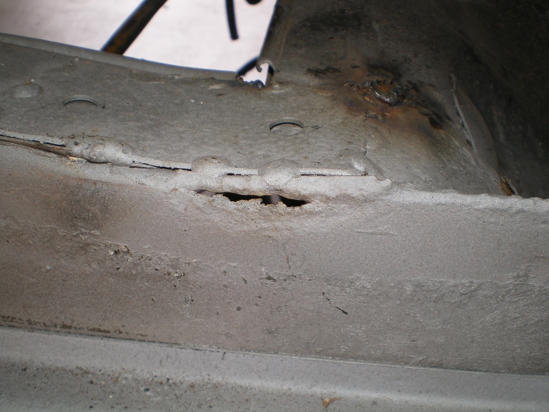 Another look at it from below, looking up. See the crack of light? No you can't because it's the last pic in this post. Don't know how I did that but could'nt correct it. lol The backup spoon in place.......... 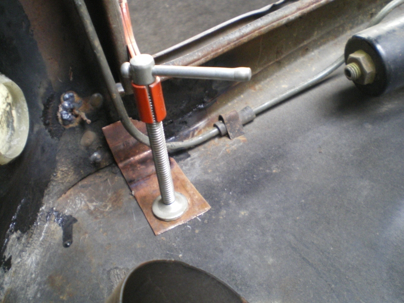 Another look at it from the cabin side this time. Flash really puts a tinge to the color. Anyway you can clearly see the copper in the pic. 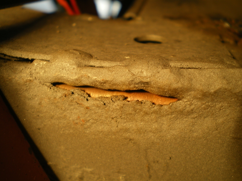 In this pic you can see where the crack was filled and ground down (on the left side). See the "V" area to the right that has rusted away. Imagine that area going another 1" down and that is how far the rust traveled on the back side. This area is close to that pull tube which gets a lot of work so I want to reinforce this area. 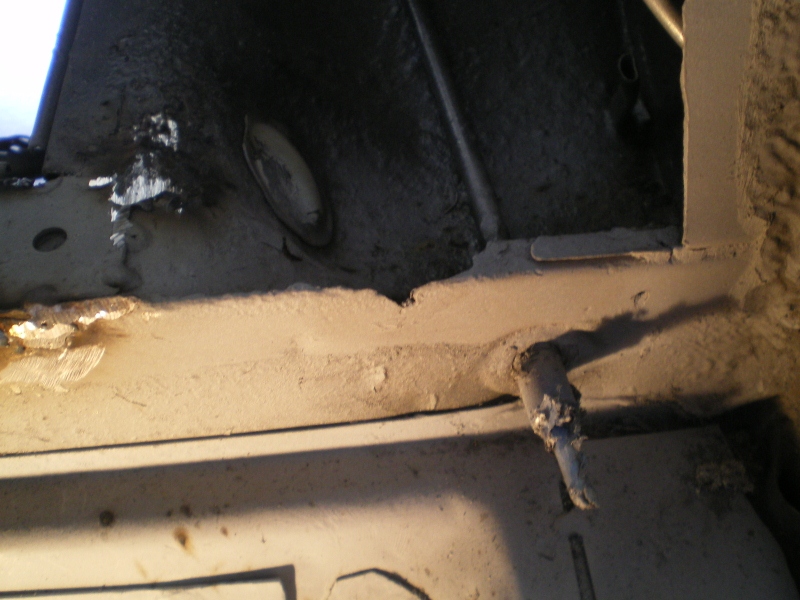 In order to do this I need to make a pattern..... 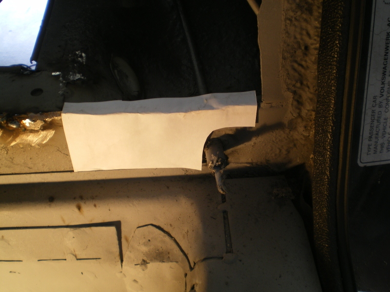 And a piece of .045". 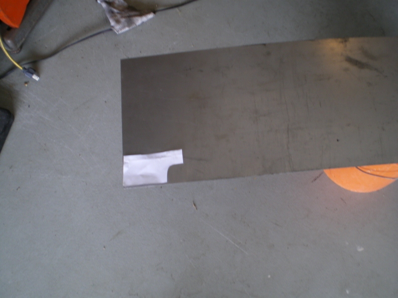 The pattern is taped in place and traced onto the steel piece. 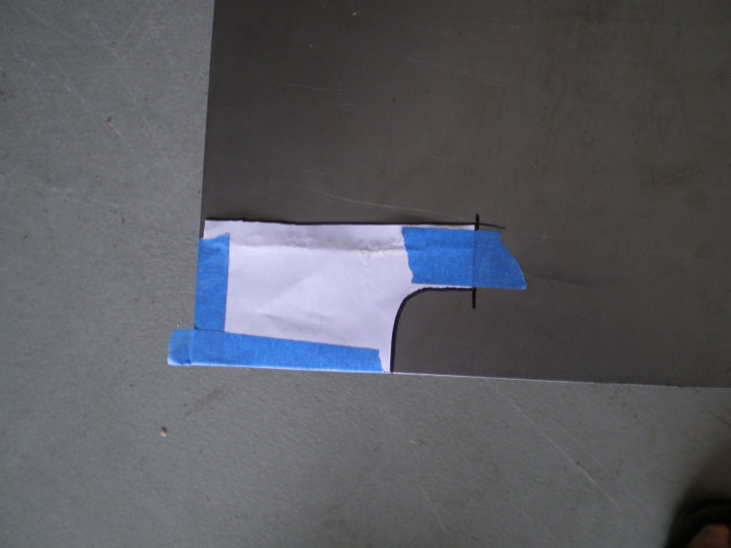 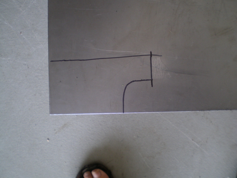 A quick cut out. This piece will be trimmed and edges polished with 3M wheel before it is welded in place. 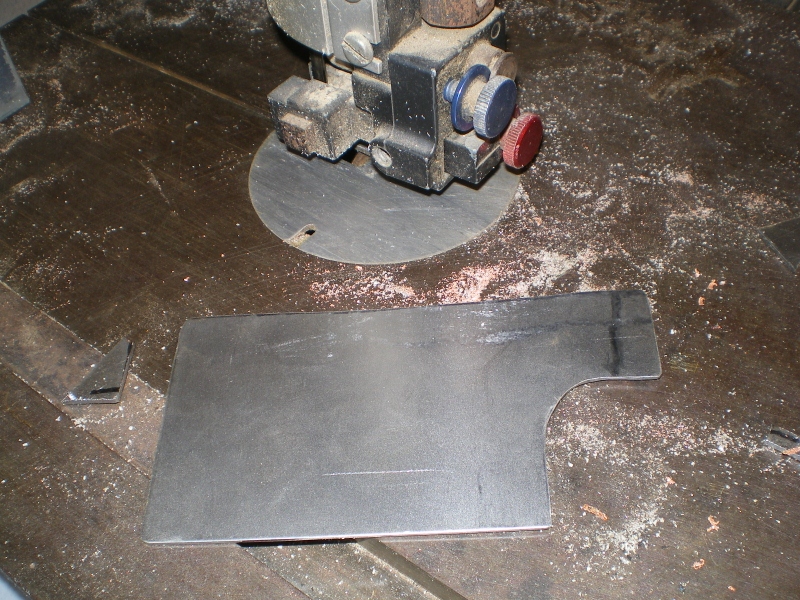 Initial fitting......... 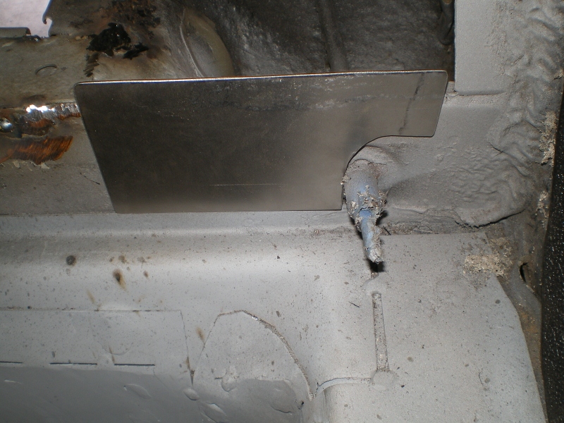 See the saw blade? It's laying on what is left of the old flange. It does 2 things. It gives an accurated location for a bend reference and #2, with a little movement it will scribe your piece for you. 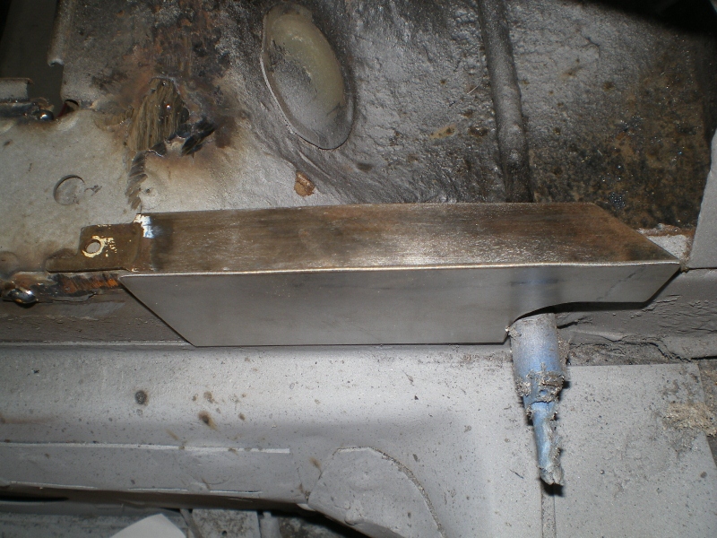 With the piece scribed (I marked the scribes w/felt tip to show in the pic's) we are ready to mark the bend line. I thought we just did? (IMG:style_emoticons/default/slap.gif) Well close. Our mark is where we want the bottom of our flange to end up, right? To get there accurately we have to take a couple of things into account. The thickness of our metal and the bend radius. In this case the metal is .047" and the bend radius is .0675". Add those 2 numbers together, subtract them from your reference line and mark your bend line. 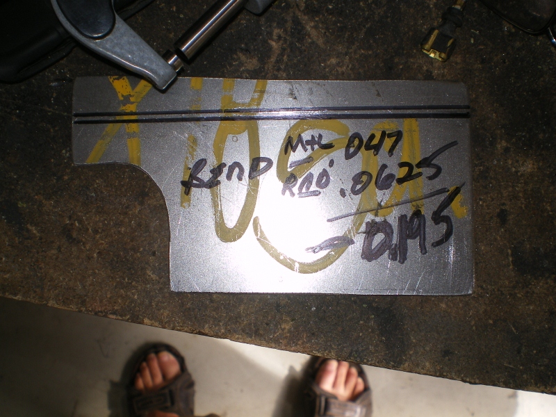 Years ago I did this and you might also. These cheap Chinese vices are good for something. It's quite easy to radius "one" jaw with a file, quickly. It can be done with a long file in <5 min's and won't effect future operations. Notice the jaw on the left is radius-ed. This next part isn't important unless you want it to fit so pay attention. Notice the feeler gage. The base of it is aligned with the scribe mark on the new bend line. You cannot see it but it is at the top of the fat lower ink line which is for illustration. The point is that the bend line "must" be aligned with the top of the jaw(or bottom of feeler gage). 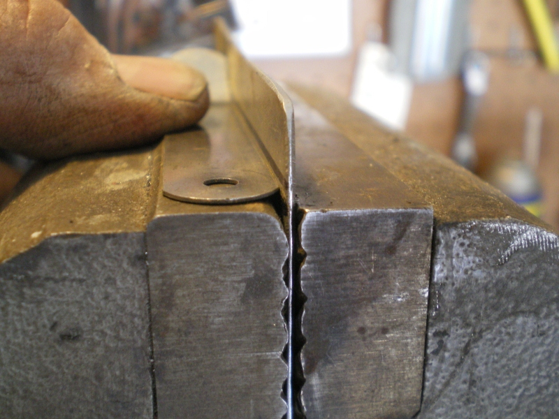 I'm using a piece of hardwood but it could be a piece of square tube as well. But I slowly hammer it down being careful to not let the wood piece rise as it is tapped. BTW, anything longer than this would require my brake but his is < 6" so no biggie. 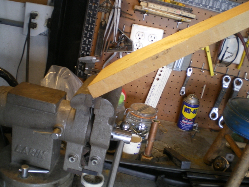 Attached image(s) 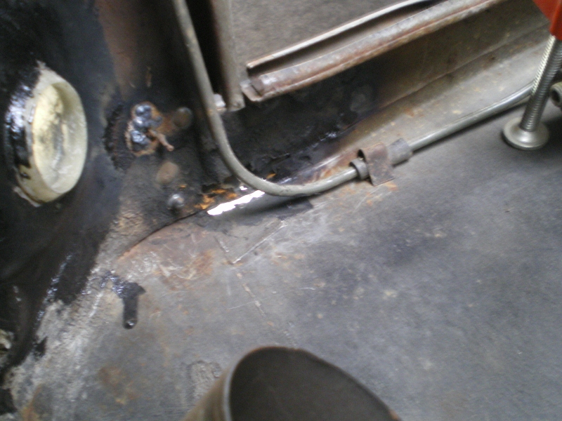
|
| 76-914 |
 Feb 3 2013, 08:18 PM Feb 3 2013, 08:18 PM
Post
#43
|
|
Repeat Offender & Resident Subaru Antagonist           Group: Members Posts: 13,694 Joined: 23-January 09 From: Temecula, CA Member No.: 9,964 Region Association: Southern California 
|
Here we see it taking shape..
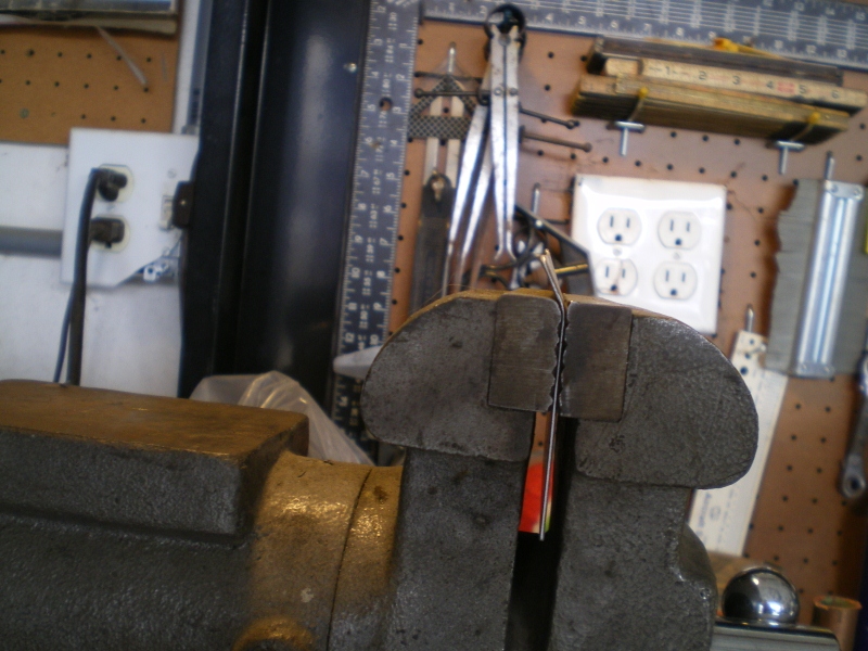 Now it is almost flat or at a 90' angle but that's as far as it is going here because of "springback" so I remove it now. Yes, I see the edge needs trimming. 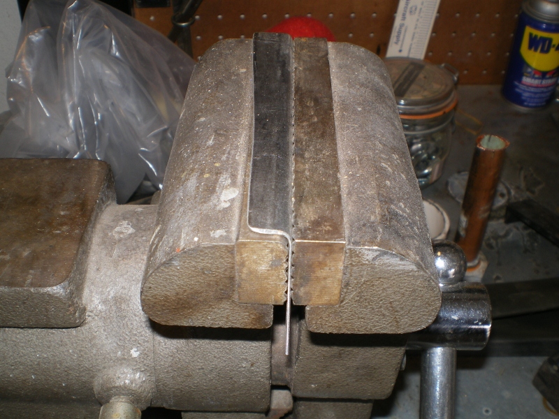 Here is the piece out of the vice, Just needs some weld holes drilled into it. 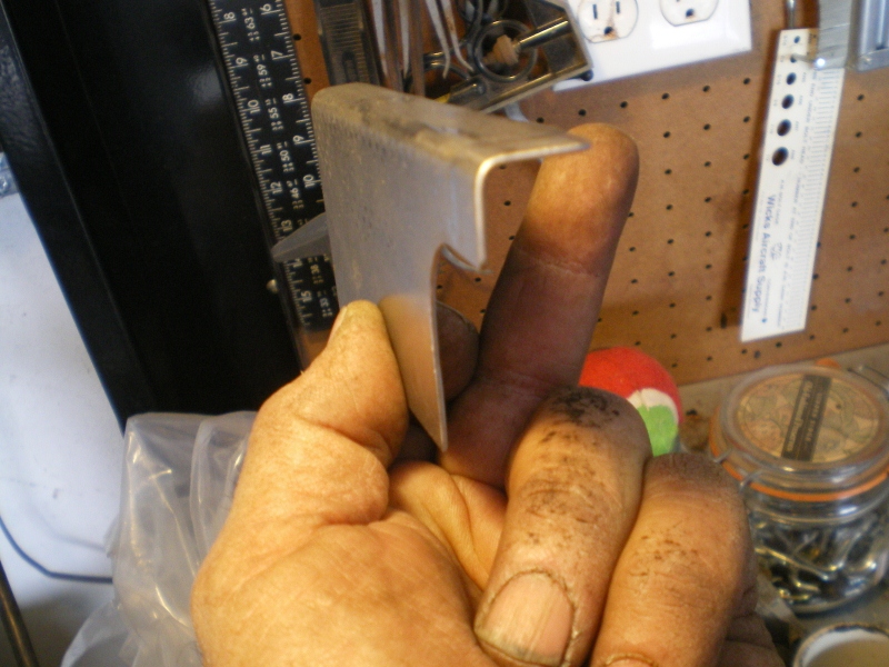 And fitted into place 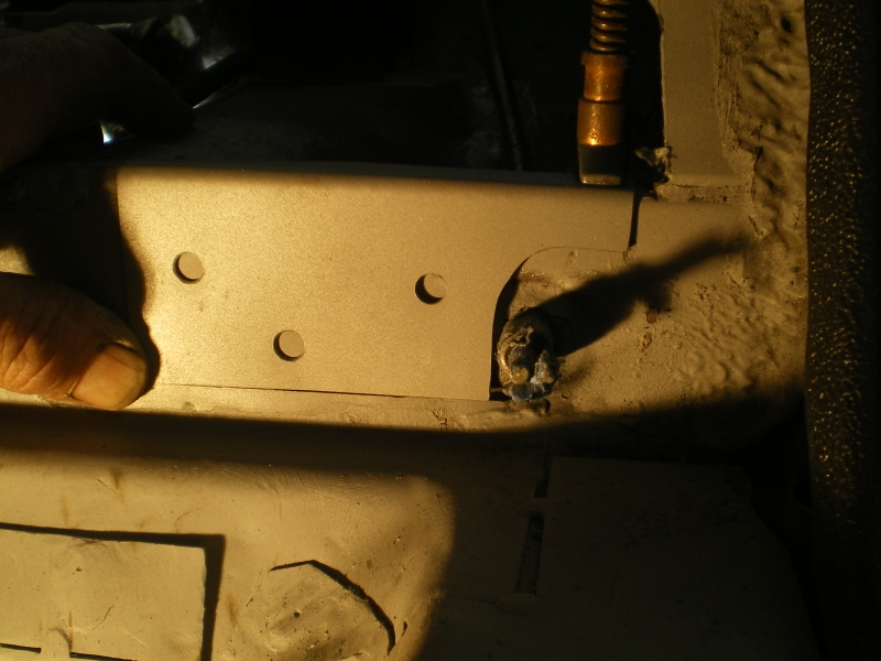 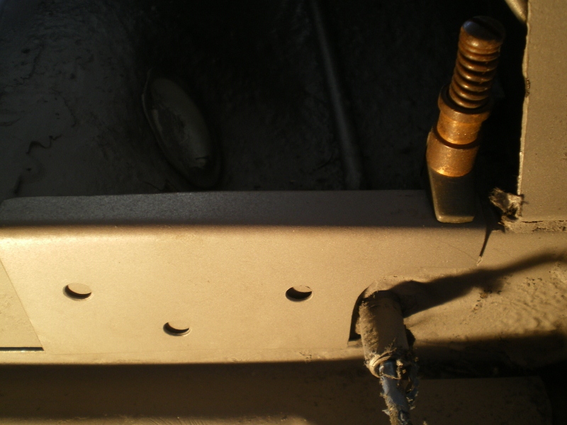 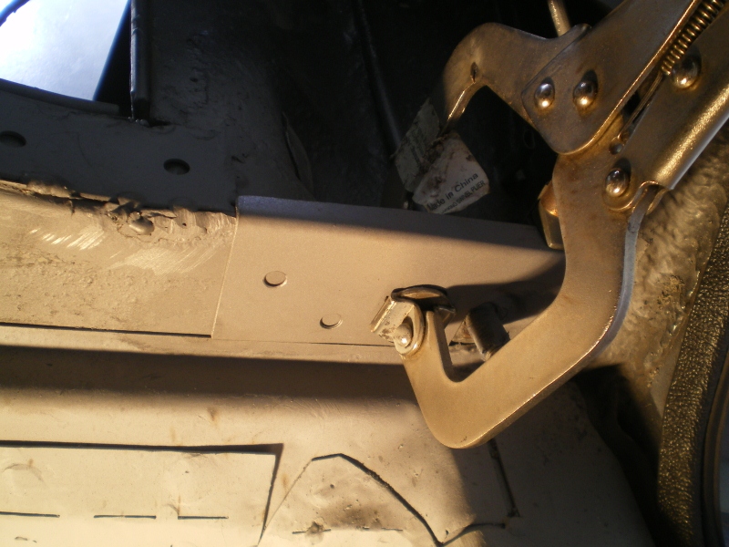 And welded in place 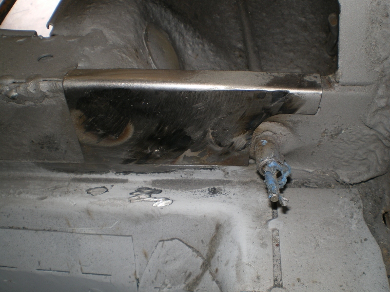 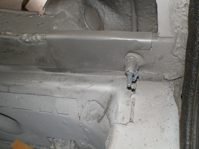 |
| Socalandy |
 Feb 3 2013, 08:46 PM Feb 3 2013, 08:46 PM
Post
#44
|
|
Its got to be Yellow!!!     Group: Members Posts: 2,432 Joined: 29-August 09 From: Orange Member No.: 10,742 Region Association: Southern California  |
Looking good Kent but who is this jester for? or were you showing the metal who's boss
Attached image(s) 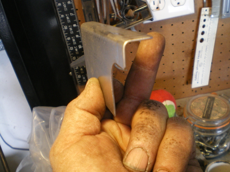
|
| 76-914 |
 Feb 6 2013, 11:37 PM Feb 6 2013, 11:37 PM
Post
#45
|
|
Repeat Offender & Resident Subaru Antagonist           Group: Members Posts: 13,694 Joined: 23-January 09 From: Temecula, CA Member No.: 9,964 Region Association: Southern California 
|
Hah, good one Andy! Just trying to hold it for the pic. I finally received the 20 ga metal today. First time they shipped 17 ga, oops. Anyway they were great about it. Bobco metals in LA. They are on the net and ship. Remember this? The psg side
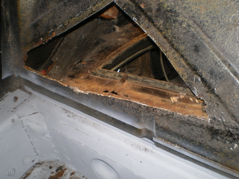 and the drvrs side 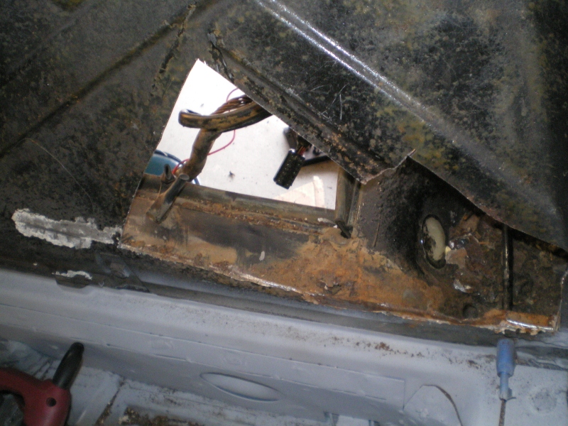 Here is a shot of the psg side pattern being traced 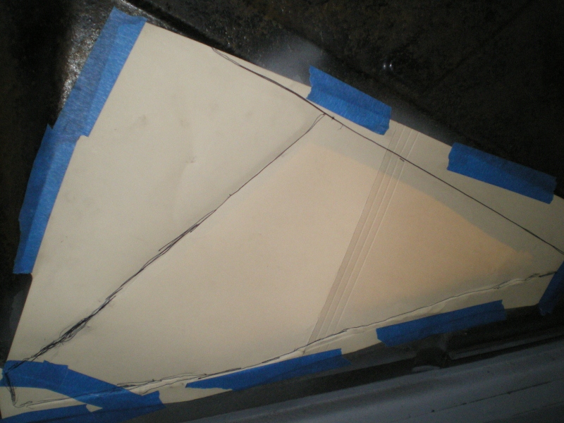 with the flash off you can see what I see, easy enough to trace out 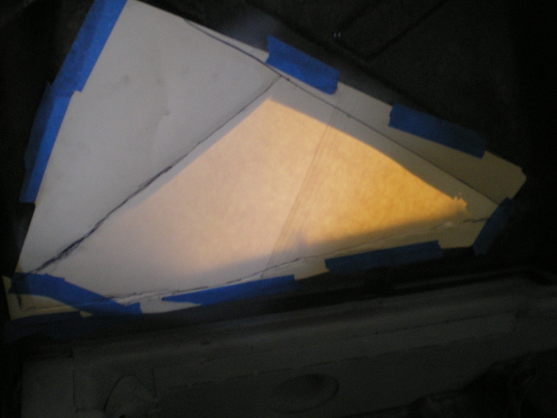 this is the first rough cut of the drvr side firewall patch piece 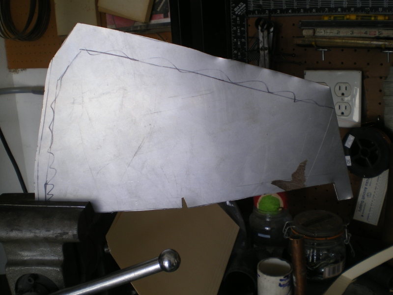 The piece placed against the firewall to check overall fit and mark for trim 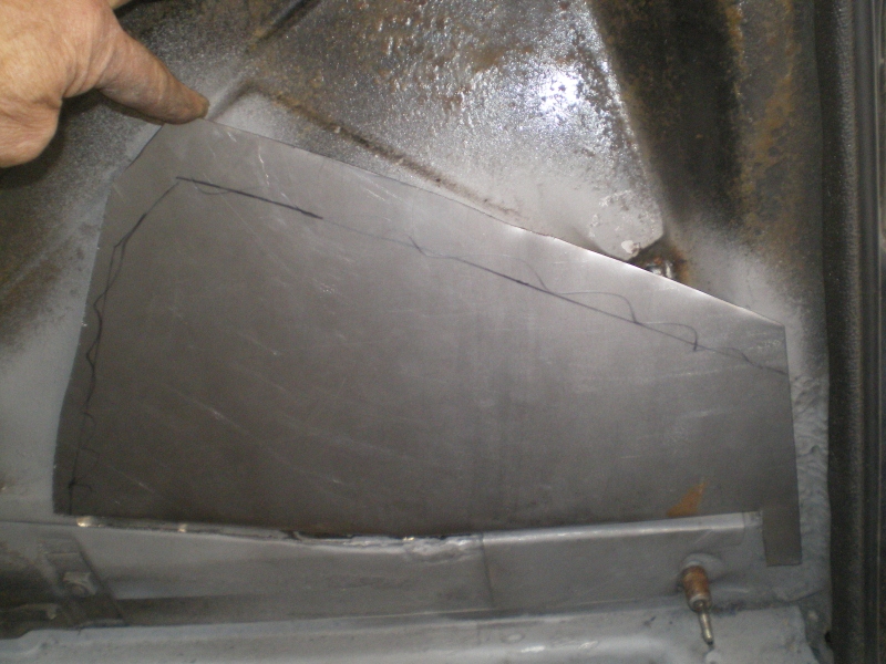 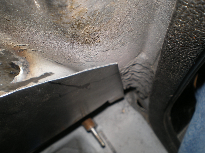 and a compound curve 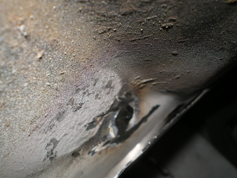 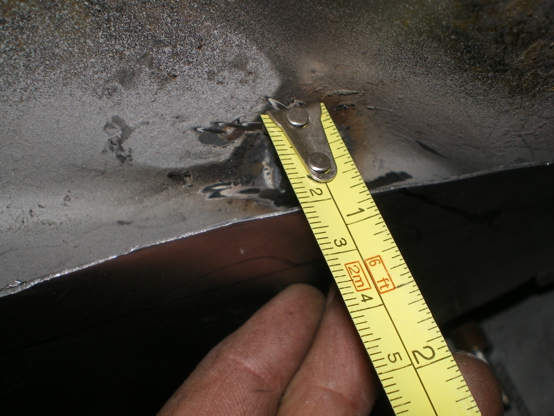 this is one of my CSOB tools I made out of water pump pliers and an old lawn mower blade years ago. with the piece firmly clamped a piece of .050" (6160) aluminum which is radiused, shown in the next pic, is driven into the steel right next to the fixture holding it. This is what created the raised portion that was necessary to meet the existing material 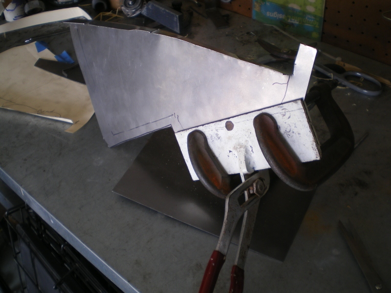 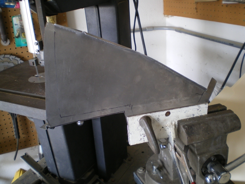 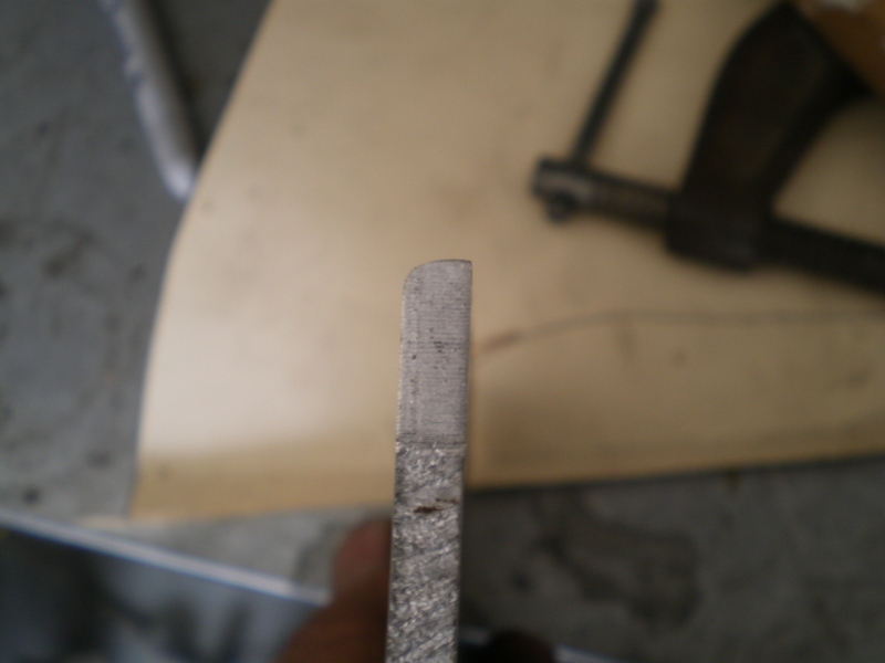 starting to take shape 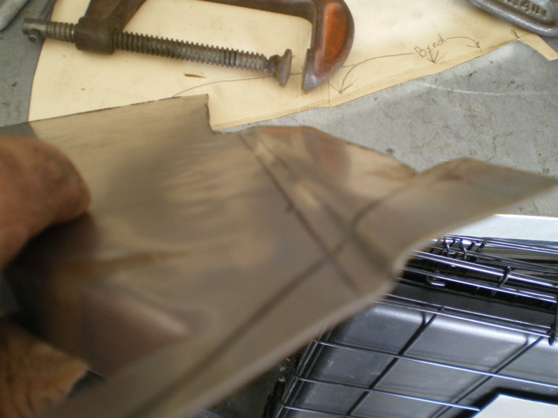 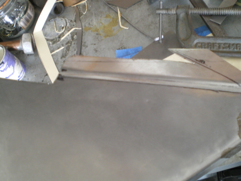 Attached image(s) 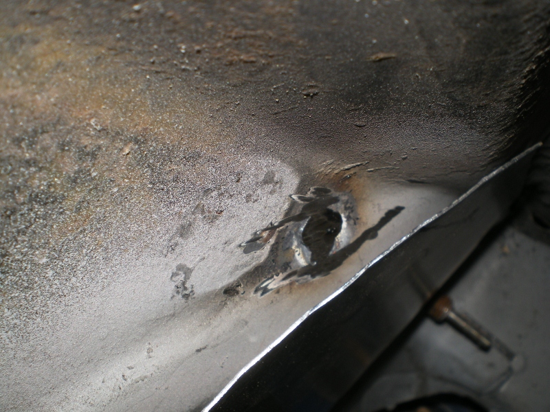
|
| 76-914 |
 Feb 6 2013, 11:37 PM Feb 6 2013, 11:37 PM
Post
#46
|
|
Repeat Offender & Resident Subaru Antagonist           Group: Members Posts: 13,694 Joined: 23-January 09 From: Temecula, CA Member No.: 9,964 Region Association: Southern California 
|
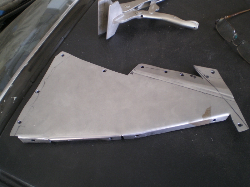 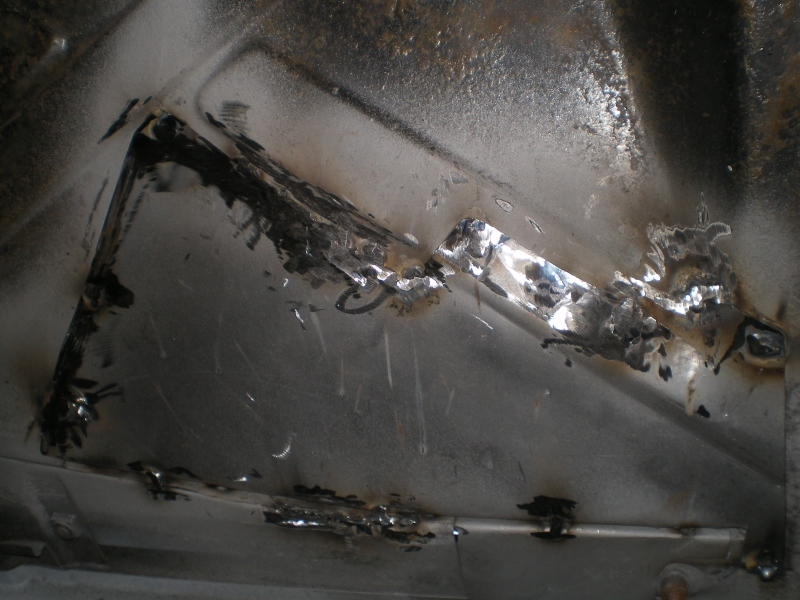 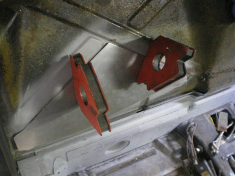 and the pass side, not much to it 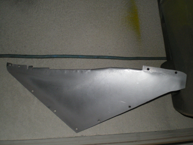 a little grinding and a little primer then it's on to the radiator 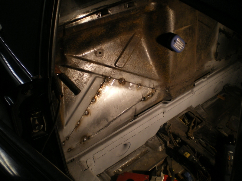 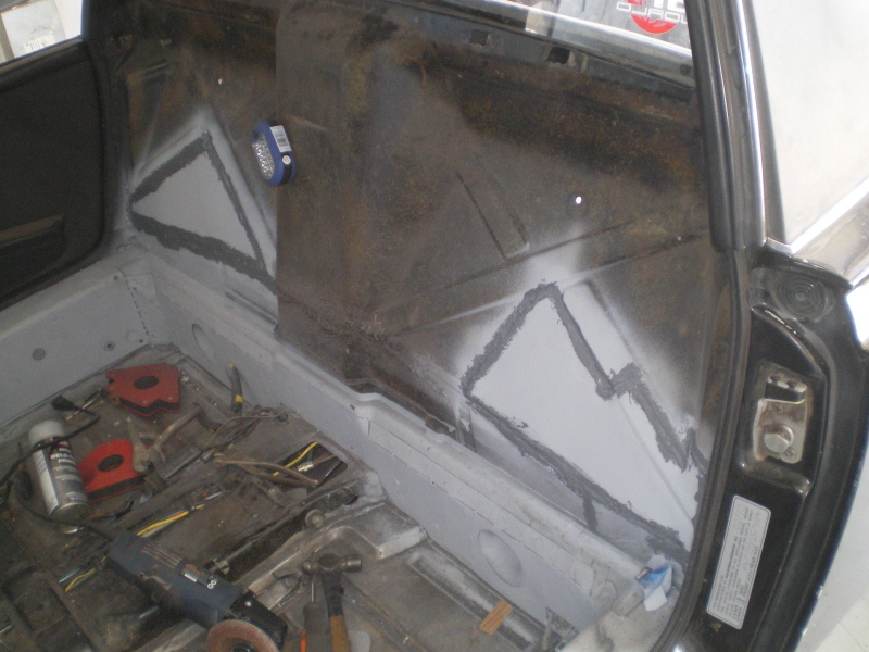 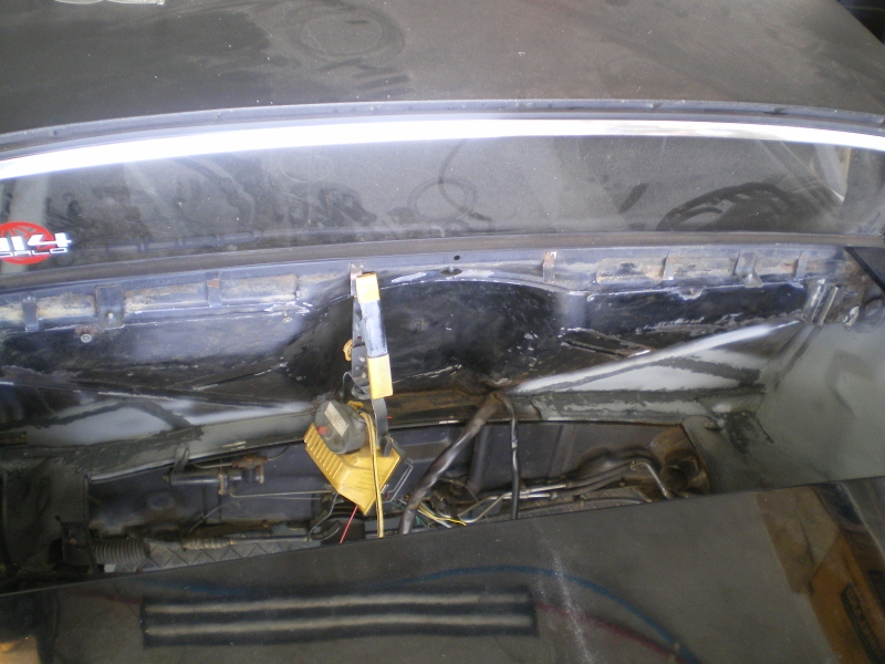 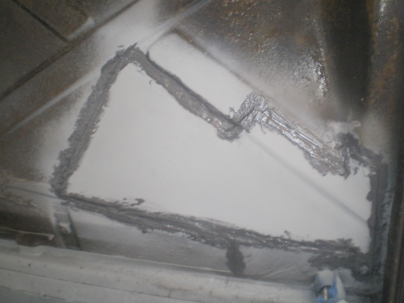 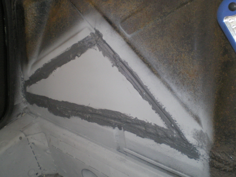 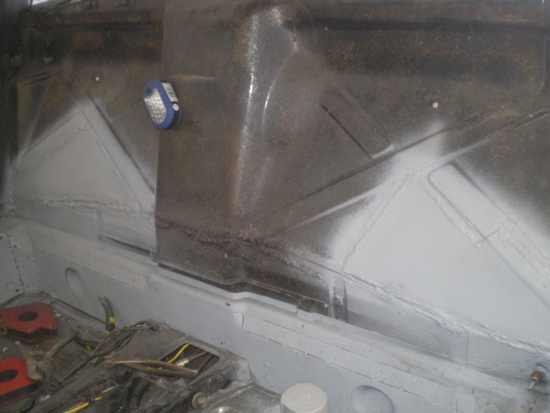 |
| 76-914 |
 Feb 7 2013, 04:59 PM Feb 7 2013, 04:59 PM
Post
#47
|
|
Repeat Offender & Resident Subaru Antagonist           Group: Members Posts: 13,694 Joined: 23-January 09 From: Temecula, CA Member No.: 9,964 Region Association: Southern California 
|
Well, with the rust repair (I think) behind me it's time to move on to the new water cooling system. I've ordered twin fan set up from EBay (thx for the tip BigKat) that I will use to begin some initial mock ups. For $45 incl shpg I can't go too wrong. If the size works I'll order a radiator to match. After a lot of reading I've decided to go the rubber hose route. Originally I believed that I wanted to run copper behind the valance thru the gussets but I thought I should avoid the plating process (IMG:style_emoticons/default/dry.gif) . While waiting for something to cool or dry I gave this a try with pleasing results. I know where I'm running my hoses now. (IMG:style_emoticons/default/piratenanner.gif)
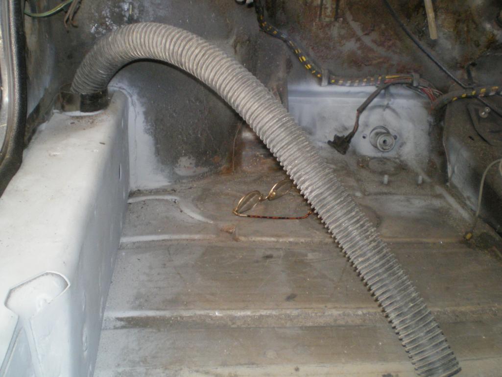 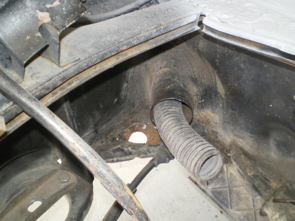 I also will be ducting thru the wheels but noticed a dent/crease on the R side. I know that area will be hacked but I needed to know if this was under stress before I began removing any material. The floor pan beneath the spare is beat to shit from bottoming out but I wasn't sure if it was a result of impact so hence my concern for the dent. It's hard to see in these pic's but the area is outlined in blue tape. 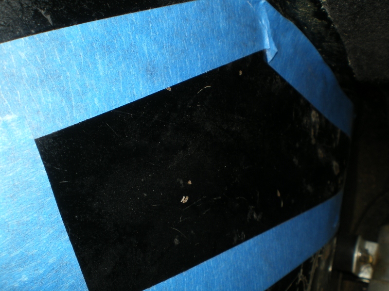 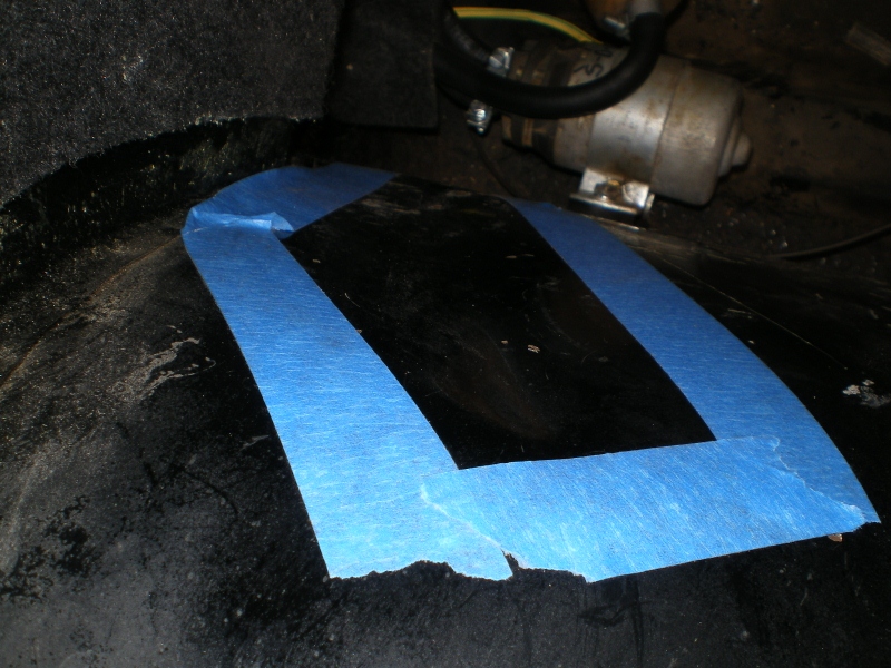 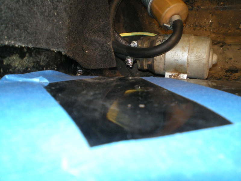 And here is my body tool. A 12lb sledge hammer with a piece of foam insulation duct taped on the end to soften the blow. 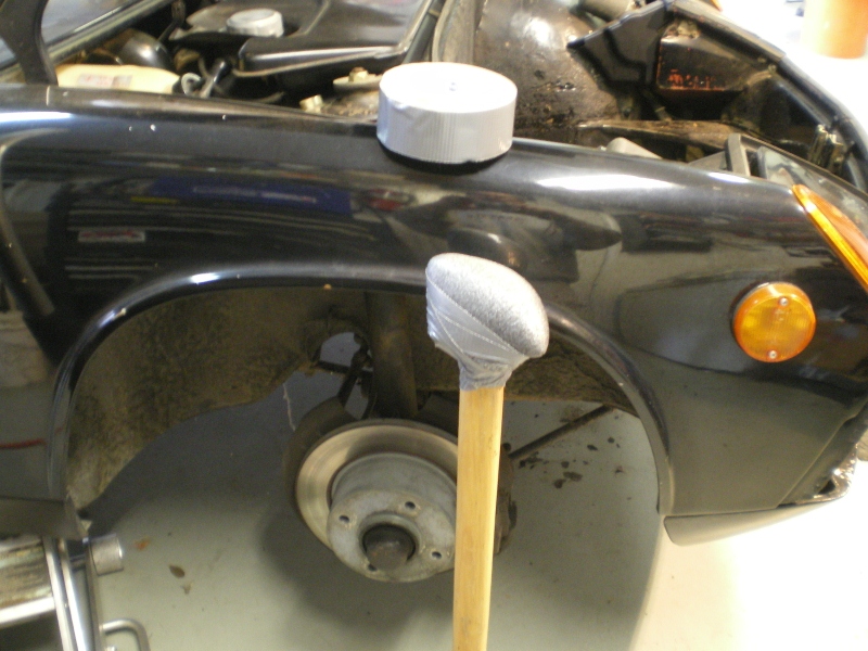 And just then my neighbor who has a dentless repair business walked in and said "What are you doing?" I said, "waiting for you". He told me that I probably would have stretched it and ended up with a bow going the other way. Talk about falling in a bucket of (IMG:style_emoticons/default/stromberg.gif) and coming out smelling like a rose. (IMG:style_emoticons/default/bootyshake.gif) Took him all of 2 min's. This is Jeremy (IMG:style_emoticons/default/pray.gif) 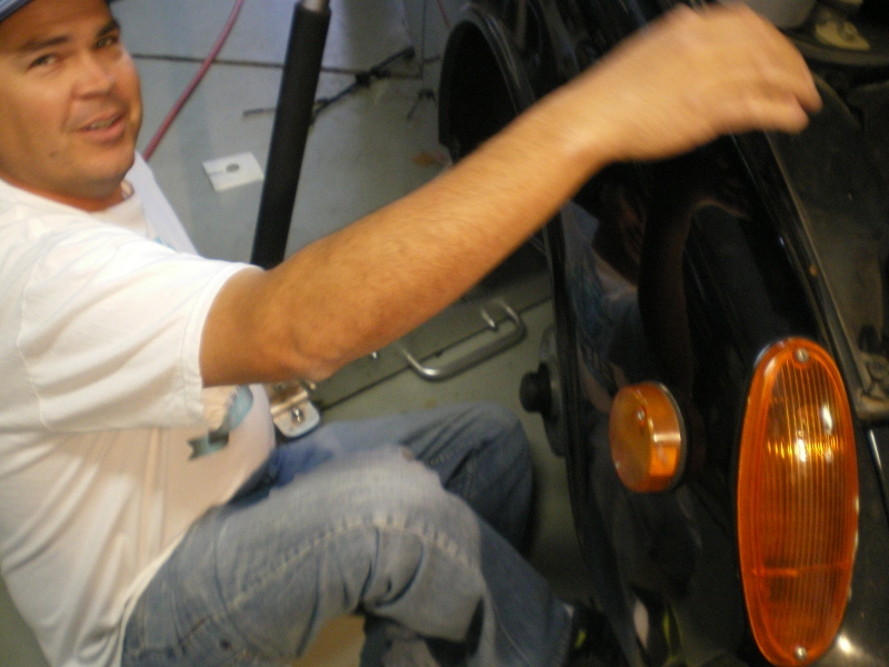 I asked Blackie if she was happy with her makeover. I think she approves. (IMG:style_emoticons/default/biggrin.gif) 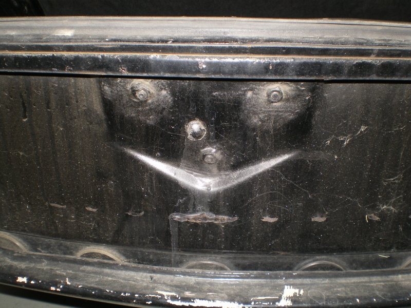 |
| 76-914 |
 Feb 24 2013, 07:58 PM Feb 24 2013, 07:58 PM
Post
#48
|
|
Repeat Offender & Resident Subaru Antagonist           Group: Members Posts: 13,694 Joined: 23-January 09 From: Temecula, CA Member No.: 9,964 Region Association: Southern California 
|
It's been too long so I'll post what I have. I've held back because the first fan assm has a bad bearing on one of the units and I ordered the wrong replacement (IMG:style_emoticons/default/headbang.gif) Jesus H. Anyway the radiator is held up in the snow storm so I went with "what I got" for now. I placed to fan unit for a quick birds eye view. Looks doable. Thanks for the tip BigCat. I went with your radiator suggestion too but it's not arrived.
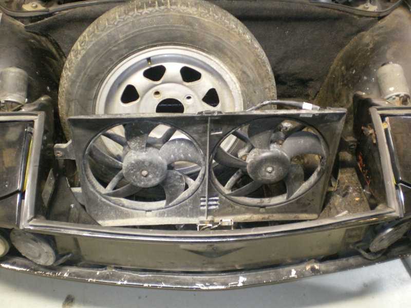 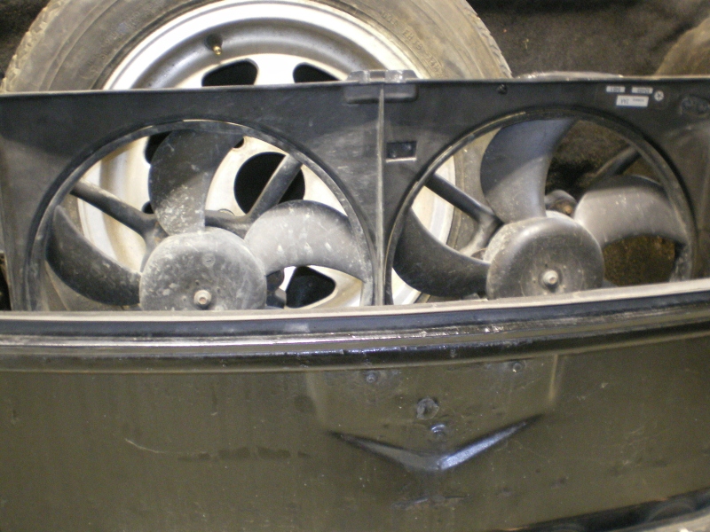 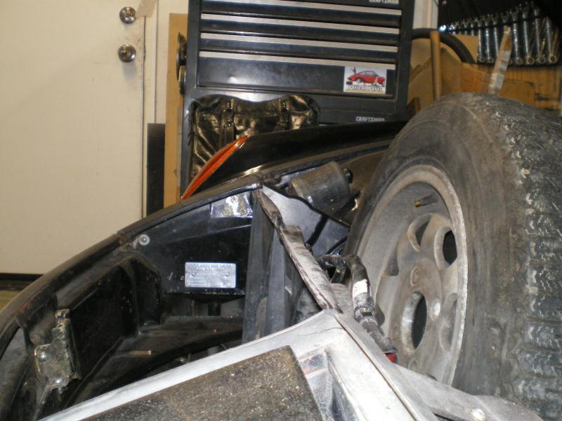 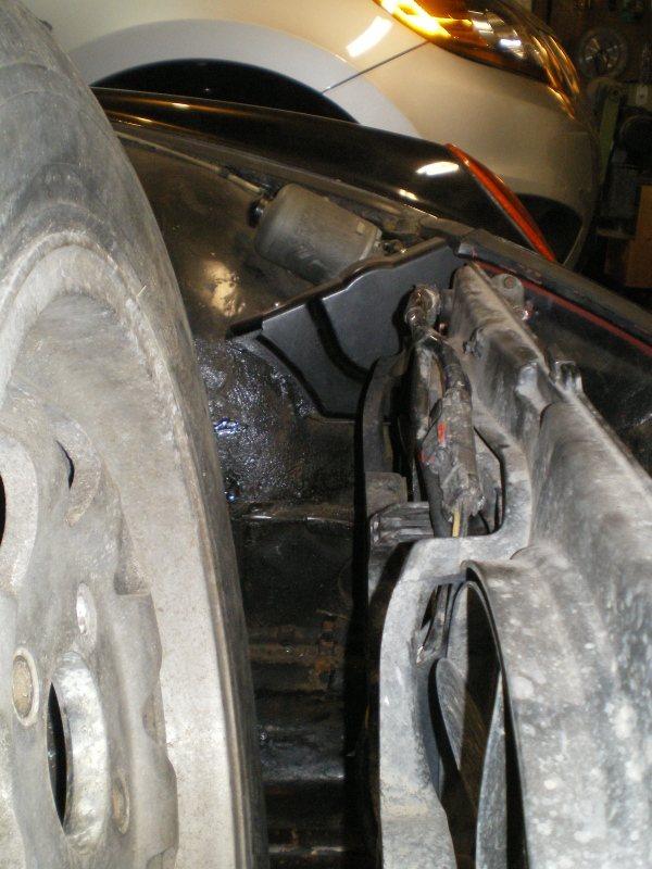 My plan ( I'm playing like I know what I'm doing (IMG:style_emoticons/default/happy11.gif) ) is to seal or box off the area immediately between the headlights to serve as a plenum of sorts. A quick temp install of the fans show they'll clear the sides enough. 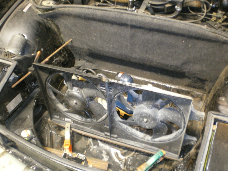 In order to do this the "box" must be reasonably sealed and here are a few lightning holes on these ribs that need to be sealed with the cardboard templates attached. 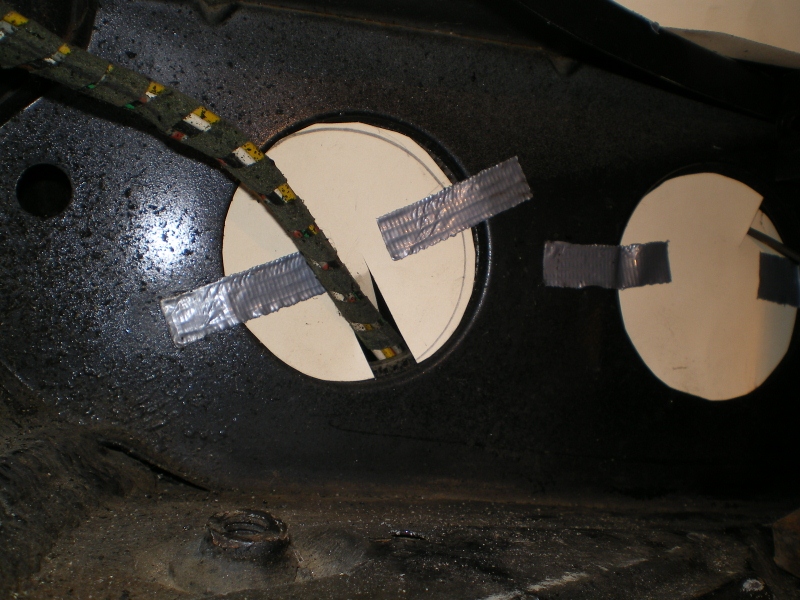 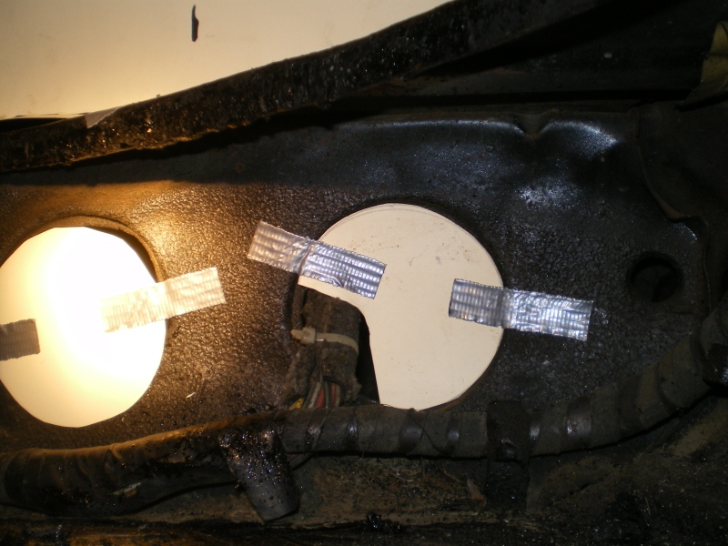 A few more but with the templates for the side pieces that will double as seals and attach points, I think (IMG:style_emoticons/default/smoke.gif) 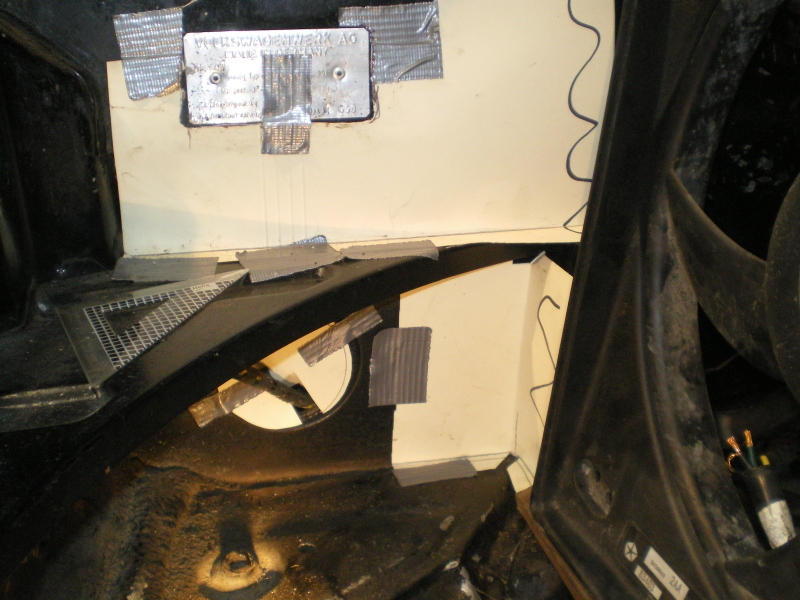 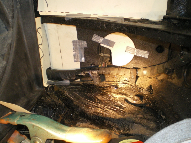 |
| 76-914 |
 Feb 24 2013, 08:18 PM Feb 24 2013, 08:18 PM
Post
#49
|
|
Repeat Offender & Resident Subaru Antagonist           Group: Members Posts: 13,694 Joined: 23-January 09 From: Temecula, CA Member No.: 9,964 Region Association: Southern California 
|
A few blanks Wurther'd into place
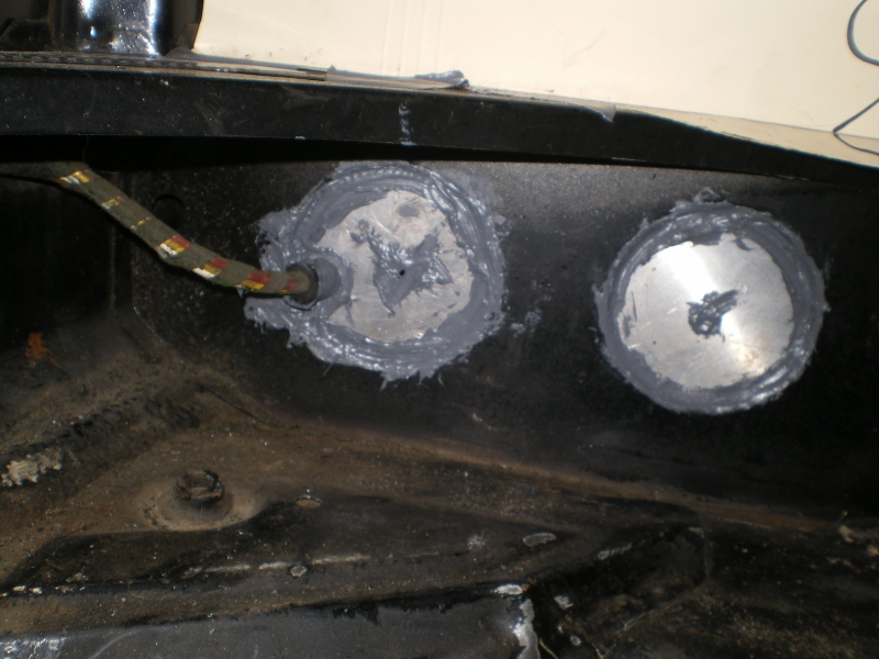 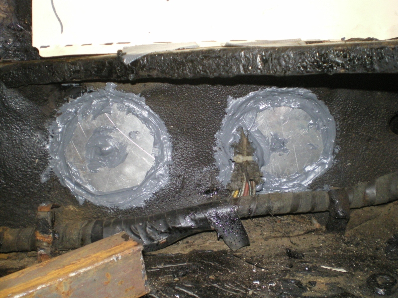 Another view 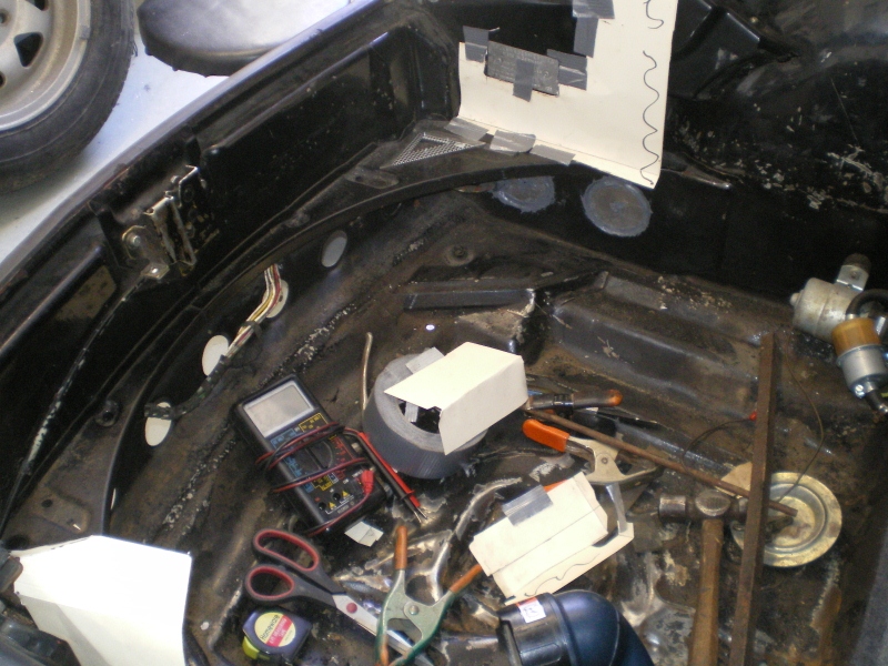 Then the brutalization 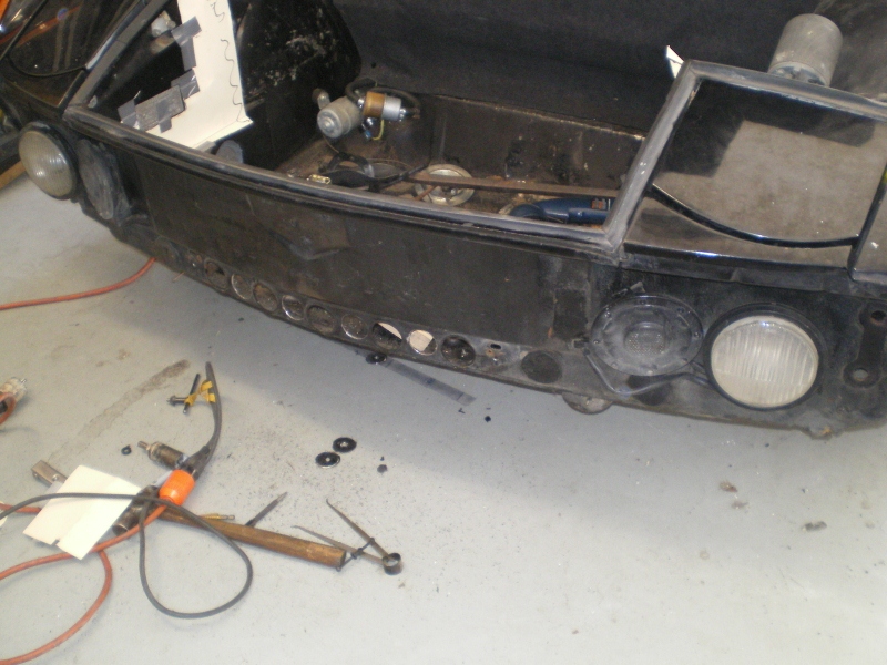 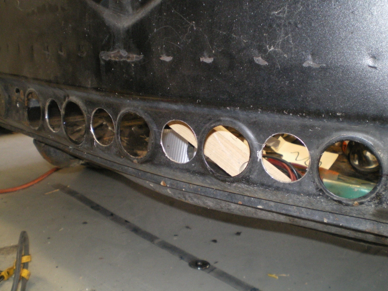 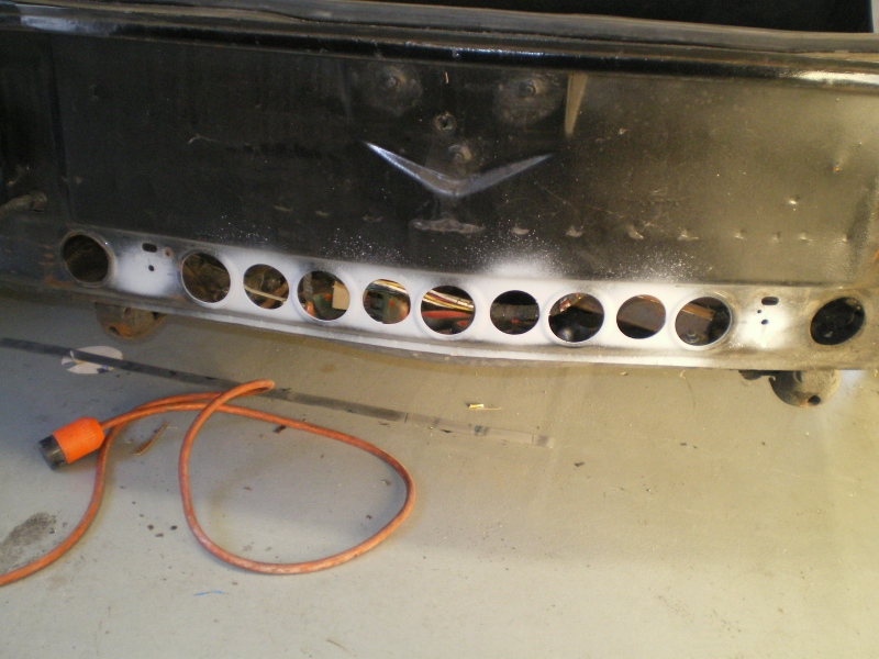 Then back to work. Here are the pieces laid out, first trim, fit in place and awaiting final bends and attach points. But that will have to wait until the radiator arrives. 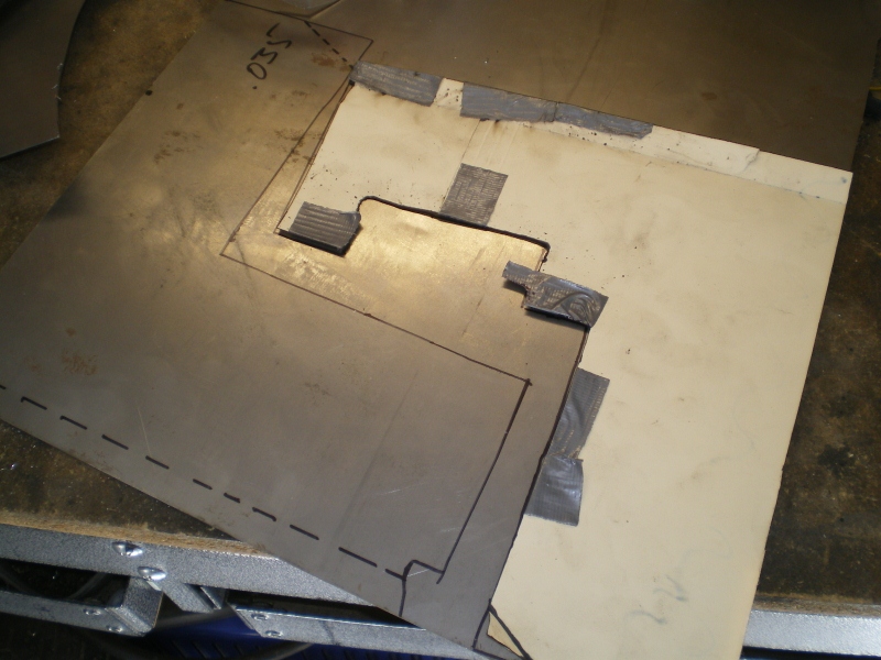 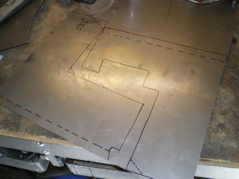 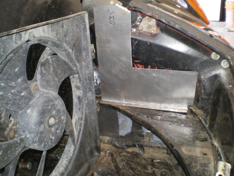 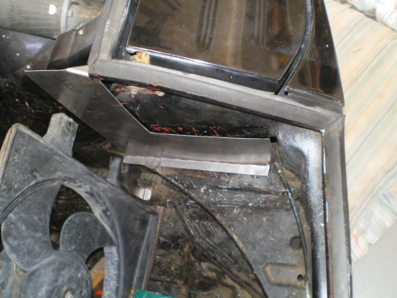 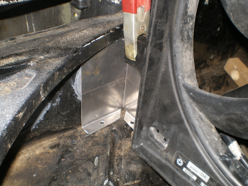 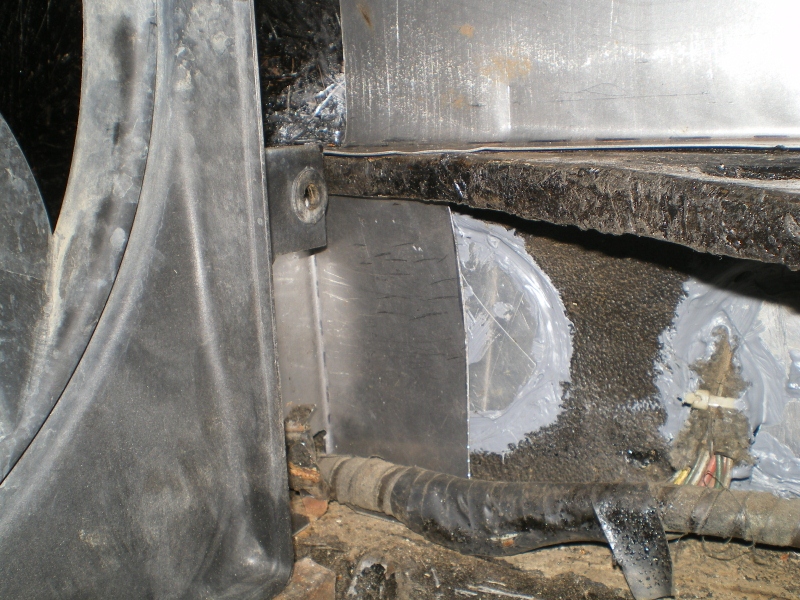 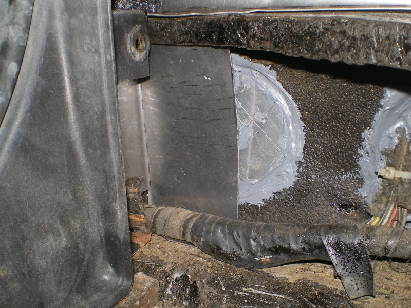 |
| 76-914 |
 Feb 24 2013, 08:30 PM Feb 24 2013, 08:30 PM
Post
#50
|
|
Repeat Offender & Resident Subaru Antagonist           Group: Members Posts: 13,694 Joined: 23-January 09 From: Temecula, CA Member No.: 9,964 Region Association: Southern California 
|
I'm going with a very good heater hose but not anything exorbitant. My heater hoses will not see the light of day so I see no need (at this time) to use green stripe or other big $$$ hoses. I was able to fish a piece thru the long w/o binding or kinking.
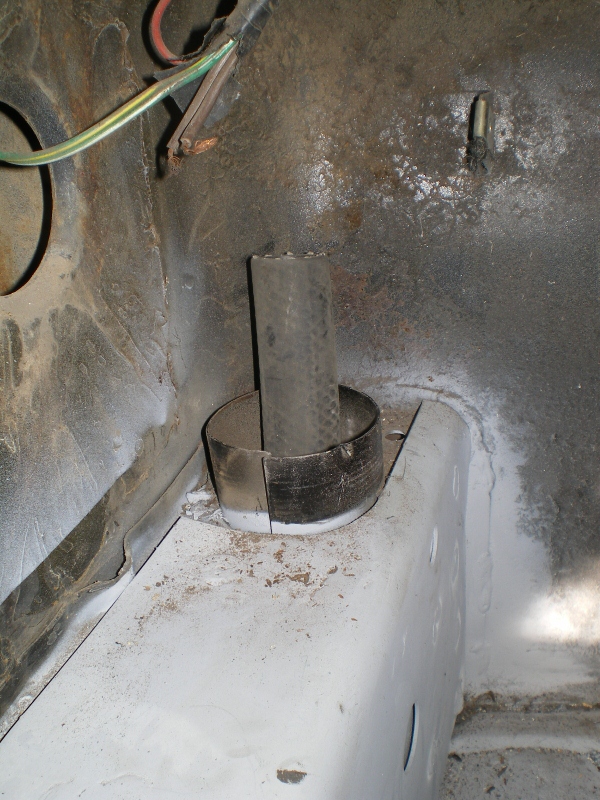 The trick is revealed. First fish the heater hose thru this vacuum/pool hose then fish the combination thru while rotating. The external hose has added benefits. It keeps the heater hose from crimping and adds some degree of wear protection to it, also. On final install I will trim the vac hose to conceal it. The metal opening will get a rubber grommet to center the heater hose where it passes thru on both ends. Will help to keep other critters out as well. (IMG:style_emoticons/default/happy11.gif) 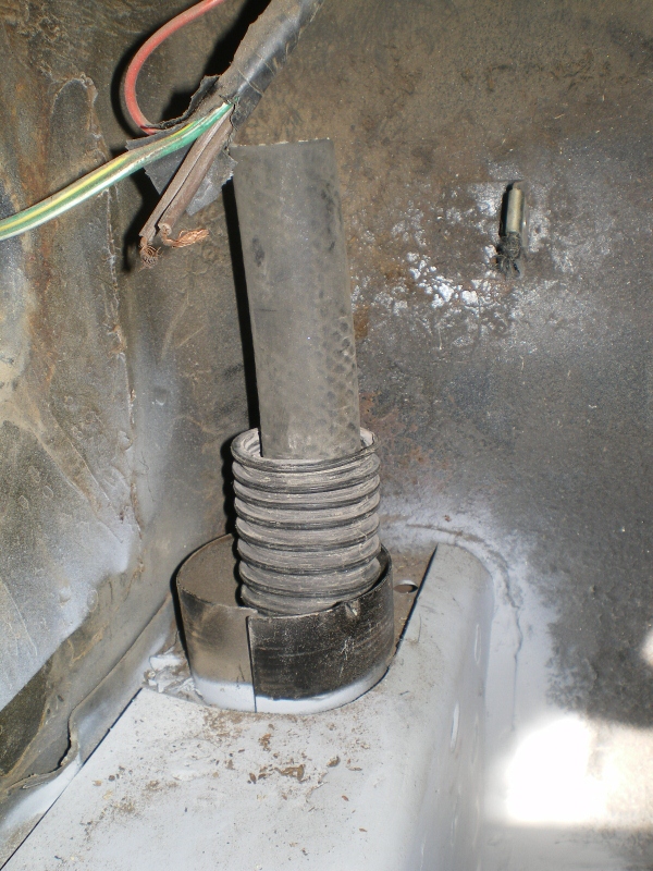 |
| 76-914 |
 Mar 3 2013, 07:36 PM Mar 3 2013, 07:36 PM
Post
#51
|
|
Repeat Offender & Resident Subaru Antagonist           Group: Members Posts: 13,694 Joined: 23-January 09 From: Temecula, CA Member No.: 9,964 Region Association: Southern California 
|
I'm glad this part is behind me. I had that thing in and out 50 times. Anywho, this is what I came up with. Let me clarify I; Bigcat suggested the radiator and fan set up. I just put em together. It's an Intrepid fan/s unit and Sirocco radiator. The fan set up is defective and was used as a mock up while a new one is shipped. The 2 are < $150 combined with shipping.
Here is the radiator/fan in it's removable frame. 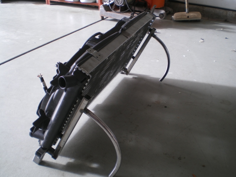 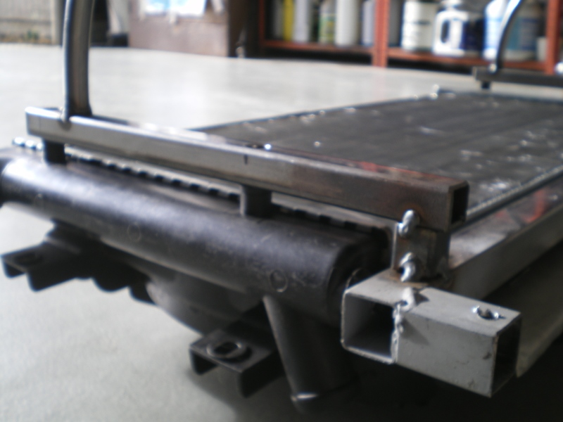 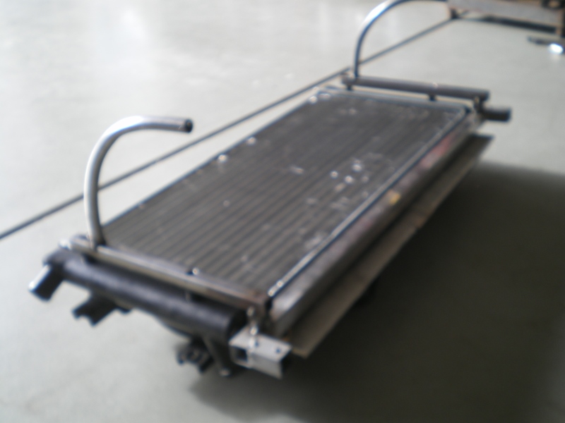 A look at the radiator to frame attach point. There are two per side. and yes those are cheese head screws. 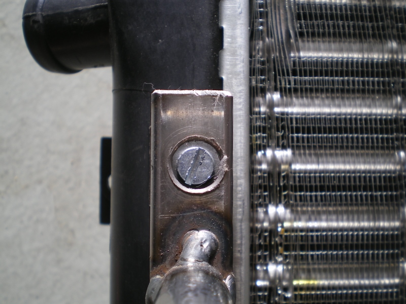 A side view of the same shot. That is a faucet washer compressed between the rad post and the frame. 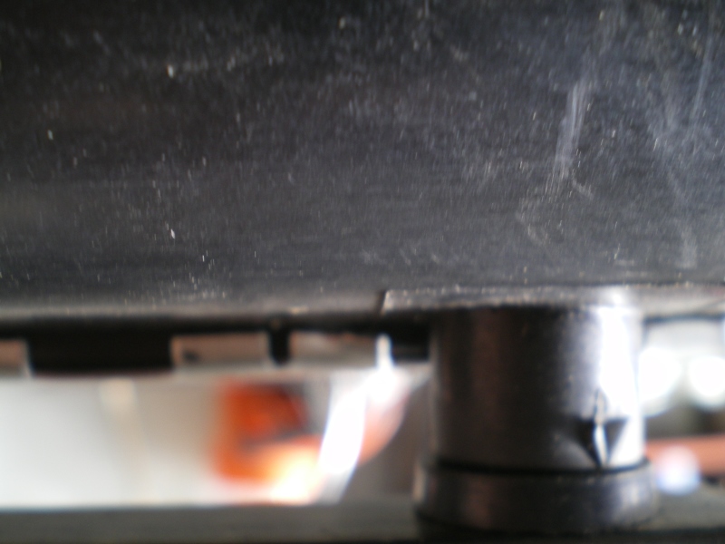 The square 1" legs of the frame will sit over these posts 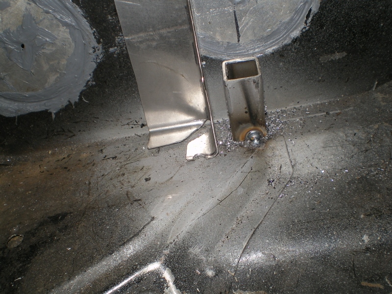 And the smaller round legs will sit atop these 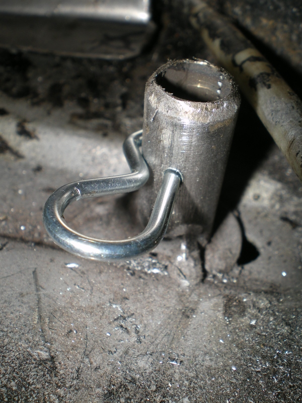 The square receiver end gets a rubber cushion 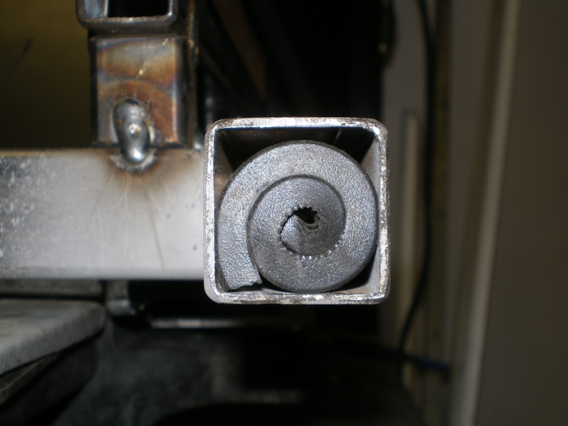 With this slightly massage washer to protect the rubber from wearing against the post. 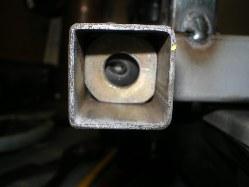 Then the unit is set and held in place by these hitch pins. For future access I will be able to remove all the radiator, shroud, etc. < 10 min's. (IMG:style_emoticons/default/biggrin.gif) 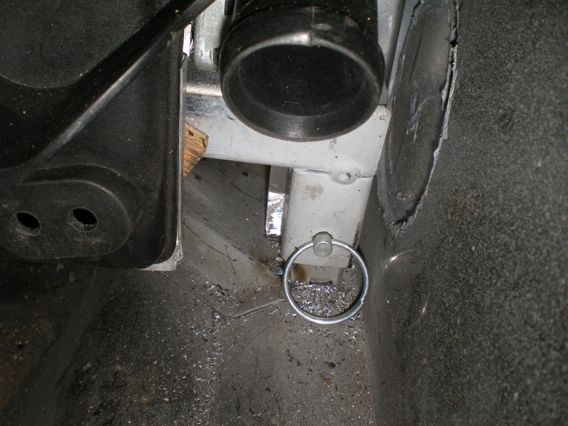 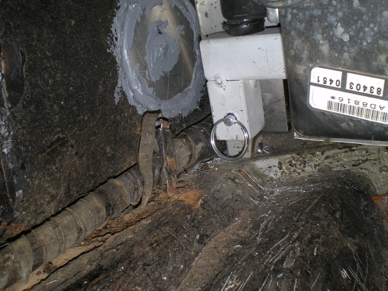 And in place 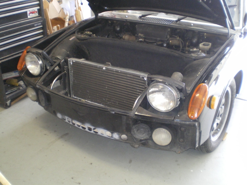 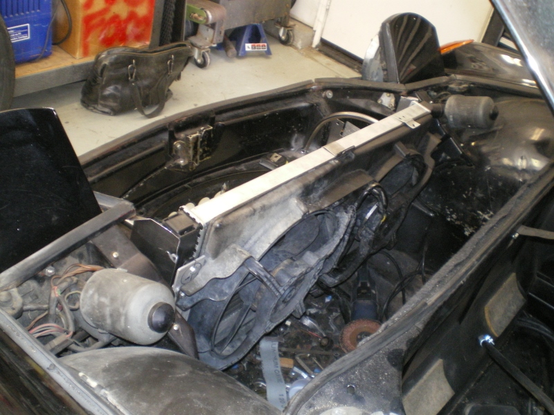 |
| Chris H. |
 Mar 4 2013, 10:36 PM Mar 4 2013, 10:36 PM
Post
#52
|
|
Senior Member     Group: Members Posts: 4,054 Joined: 2-January 03 From: Chicago 'burbs Member No.: 73 Region Association: Upper MidWest 
|
Man you are really moving fast! Great work! (IMG:style_emoticons/default/smilie_pokal.gif)
I'm still re-sealing my 3.3 and doing all the maintenance stuff but hope to be done pretty soon. |
| 76-914 |
 Mar 9 2013, 11:05 AM Mar 9 2013, 11:05 AM
Post
#53
|
|
Repeat Offender & Resident Subaru Antagonist           Group: Members Posts: 13,694 Joined: 23-January 09 From: Temecula, CA Member No.: 9,964 Region Association: Southern California 
|
Hey thanks, Chris. How's your's coming along? I was busy as Hell last week, didn't get (IMG:style_emoticons/default/stromberg.gif) done so I ended up on page 3. (IMG:style_emoticons/default/lol-2.gif) Got to hit it again yesterday so I did a final fit then welded in the side pieces that should mostly seal the gaps between the radiator and sides. There will be strips of felt or Armorflex between the metal and plastic radiator, eventually.
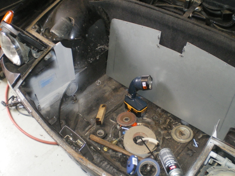 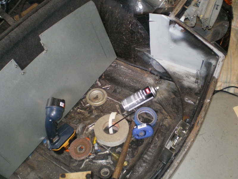 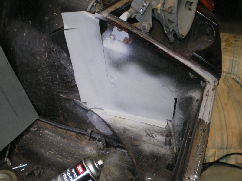 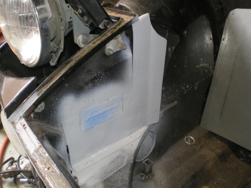 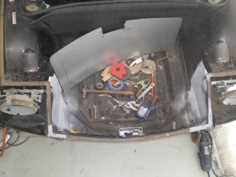 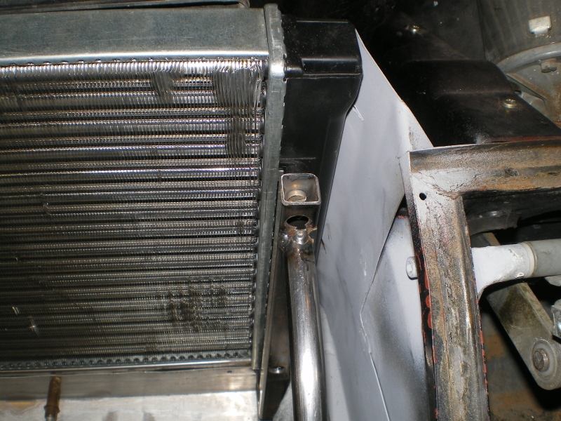 This piece will need to be massaged against the wall and then all seams and gaps get sealed with Wurth's at metal to metal junctions. 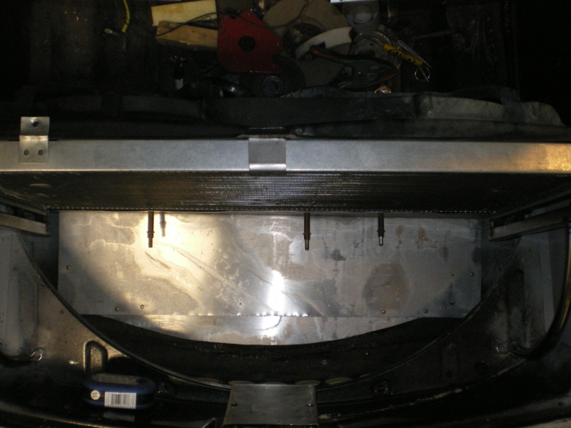 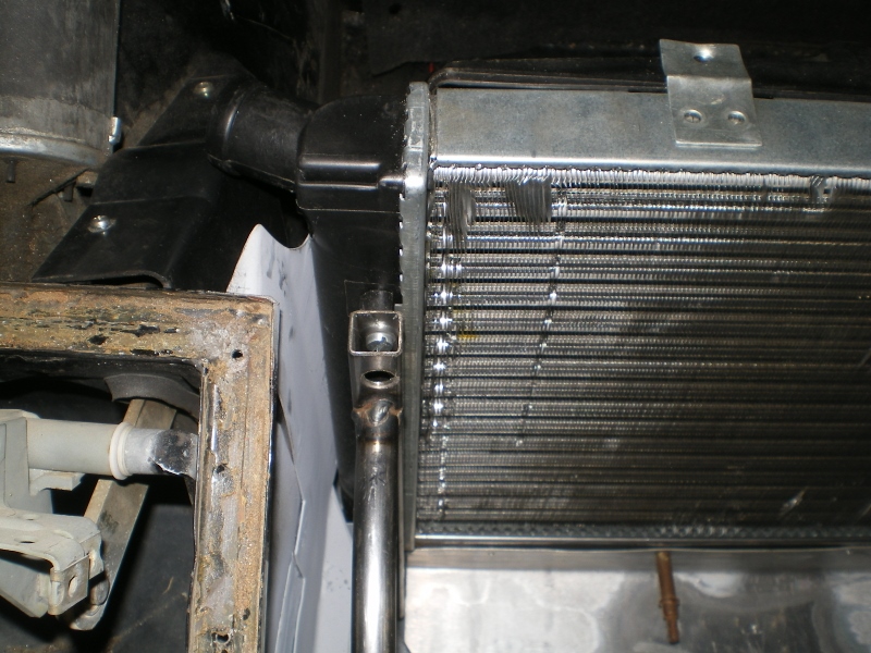 Then the bottom piece which was done with aluminum for obvious reasons. 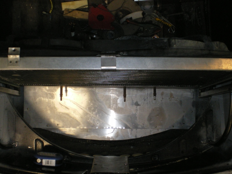 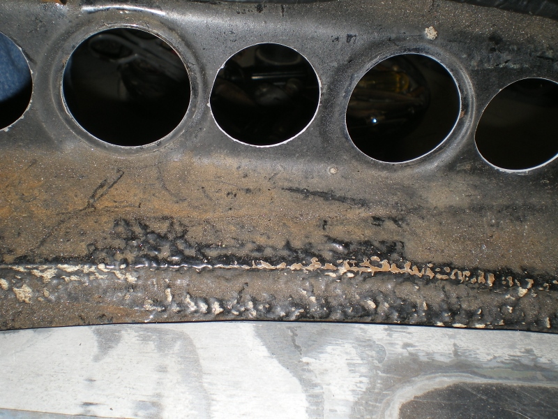 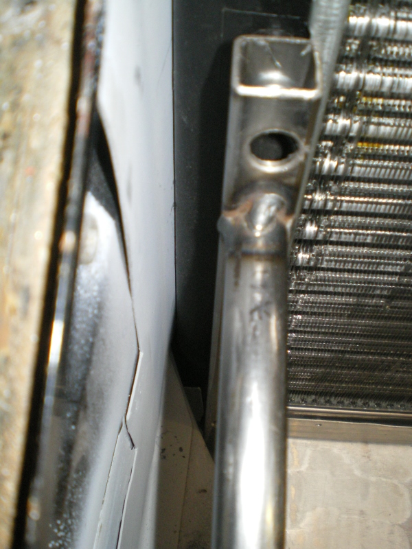 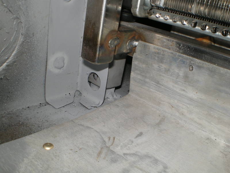 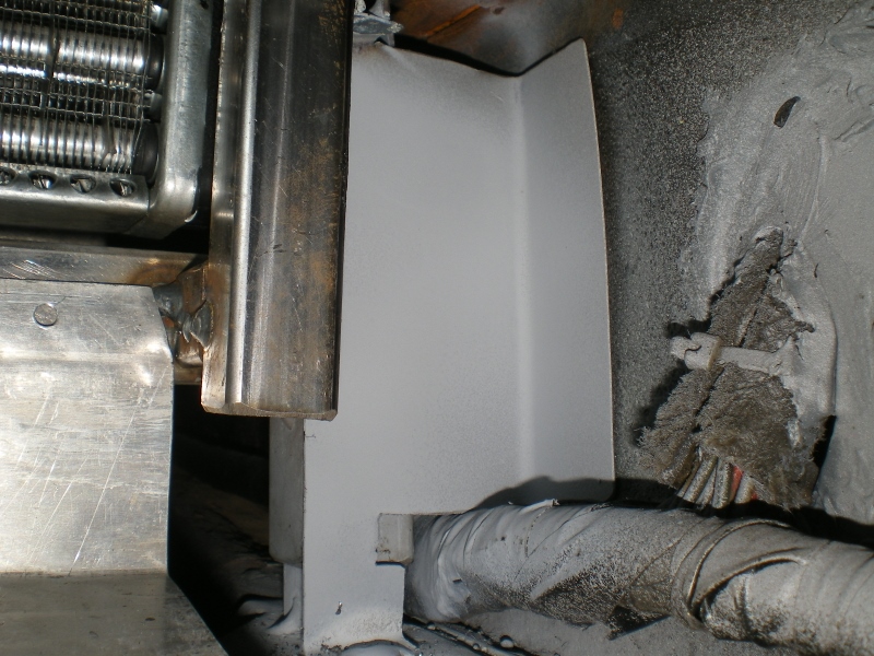 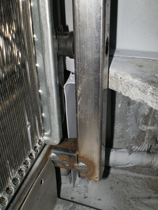 |
| 76-914 |
 Mar 9 2013, 11:06 AM Mar 9 2013, 11:06 AM
Post
#54
|
|
Repeat Offender & Resident Subaru Antagonist           Group: Members Posts: 13,694 Joined: 23-January 09 From: Temecula, CA Member No.: 9,964 Region Association: Southern California 
|
The top/cover piece slides beneath the rain channel. This piece will be pop riveted in place to facilitate easy removal. Plate nuts, rivenuts or any other kind of nut would not work as the piece slides against the bottom of the channel and anything placed there would obstruct the travel of the cover piece. I'll use blind rivets which will not allow water thru like an ordinary pop rivet would. They're only pennies each and drill out in < 5 seconds each.
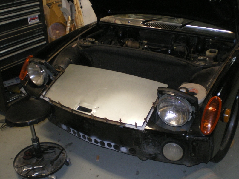 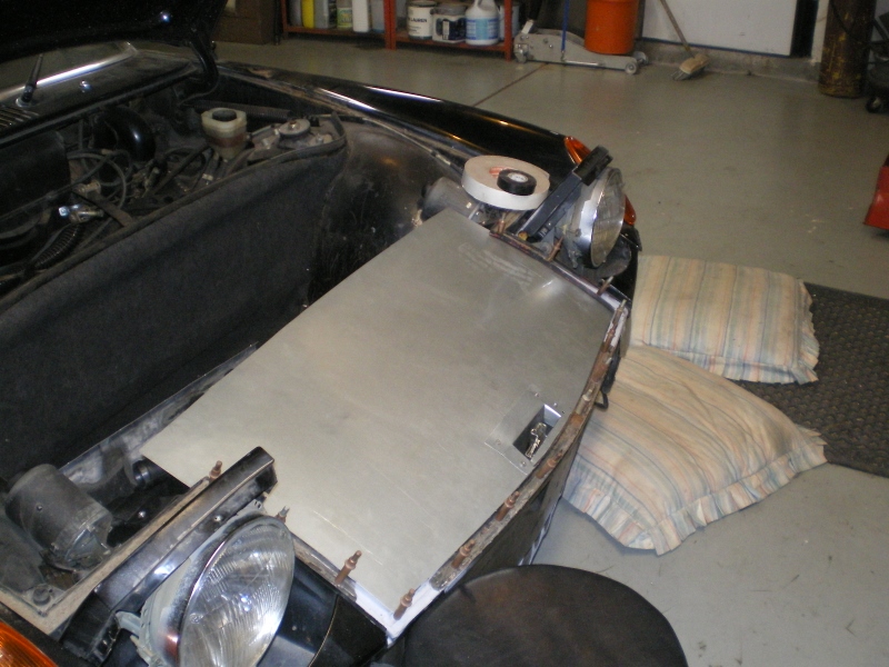 I was determined to keep the hood OG (sans Hood pins) so this is how I went about it. These screws will be replaced with black allen head cap screws. 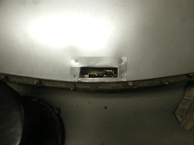 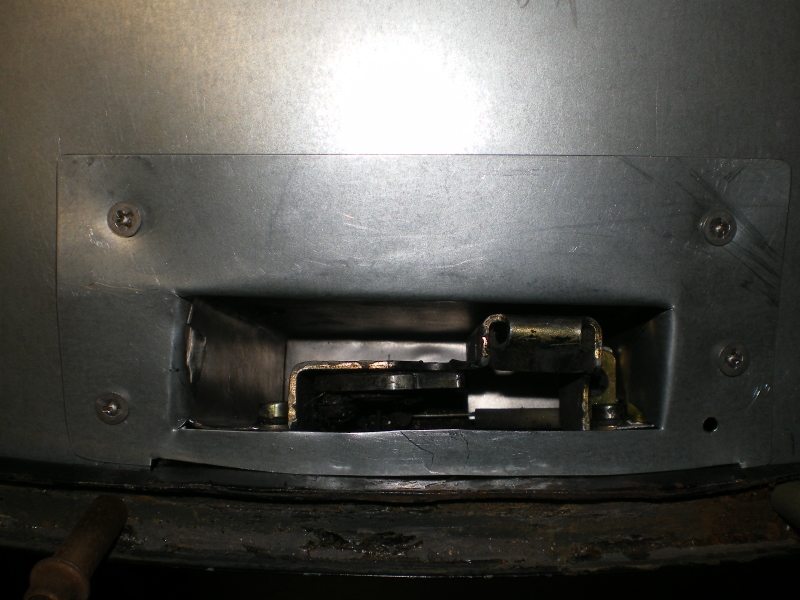 |
| 76-914 |
 Mar 16 2013, 07:29 PM Mar 16 2013, 07:29 PM
Post
#55
|
|
Repeat Offender & Resident Subaru Antagonist           Group: Members Posts: 13,694 Joined: 23-January 09 From: Temecula, CA Member No.: 9,964 Region Association: Southern California 
|
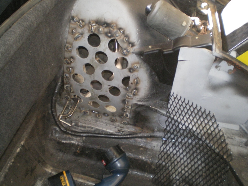
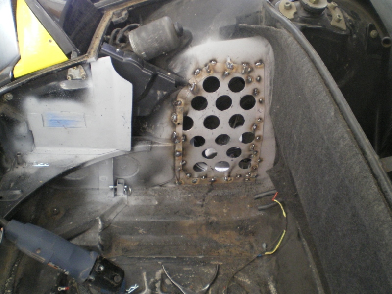
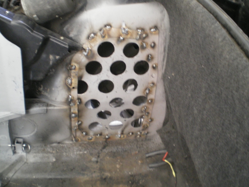
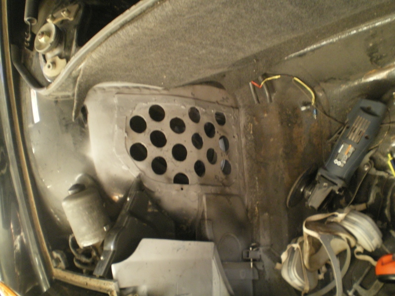
Work has been keeping me busy so this is all that I've done. (IMG:style_emoticons/default/headbang.gif)
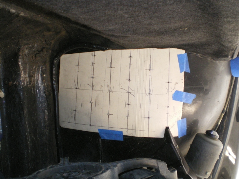 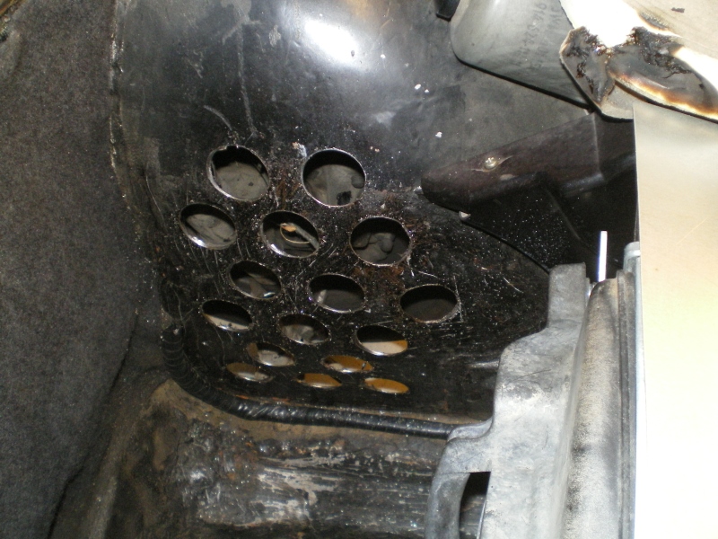 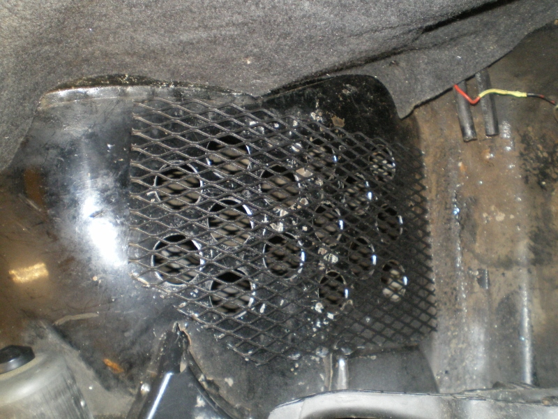 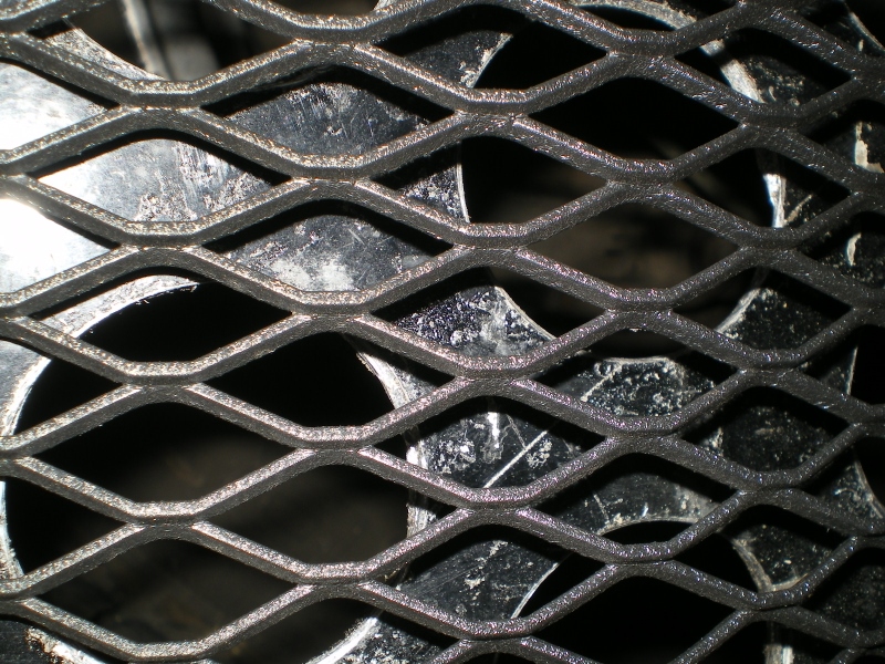     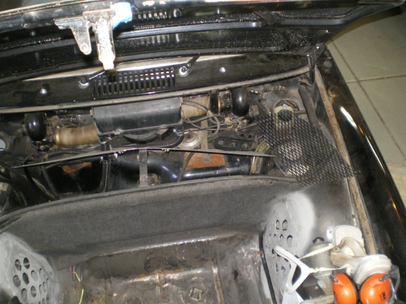 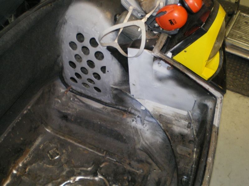 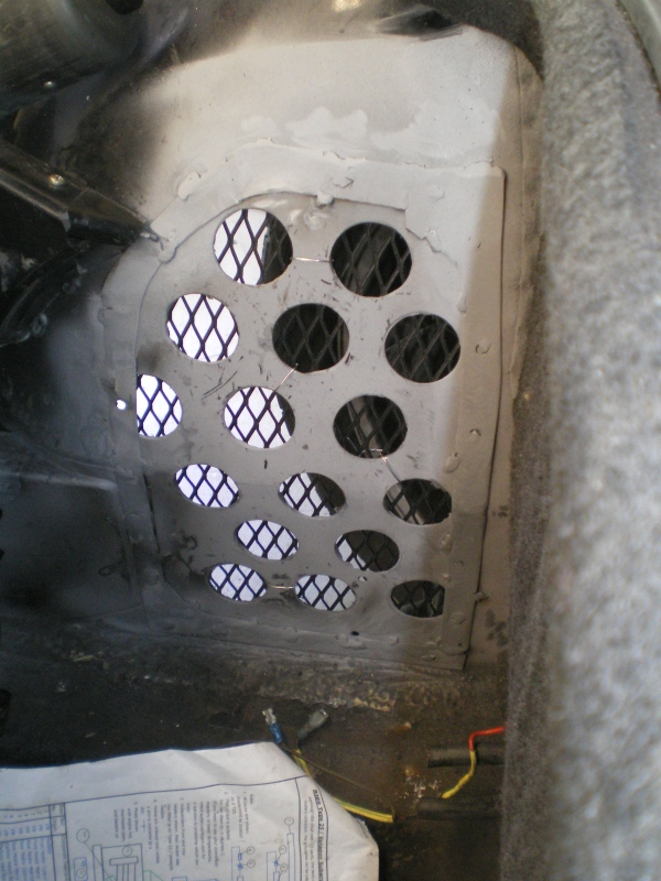 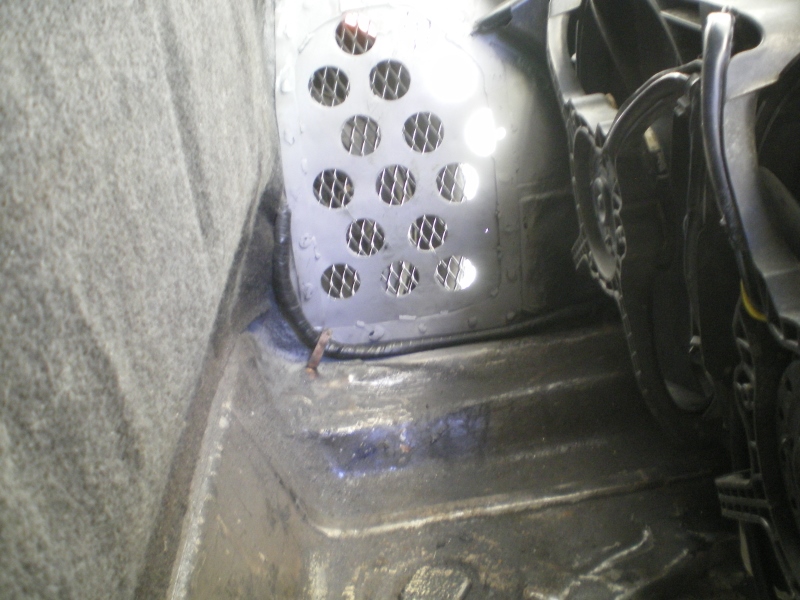 |
| 76-914 |
 Apr 8 2013, 09:23 PM Apr 8 2013, 09:23 PM
Post
#56
|
|
Repeat Offender & Resident Subaru Antagonist           Group: Members Posts: 13,694 Joined: 23-January 09 From: Temecula, CA Member No.: 9,964 Region Association: Southern California 
|
Time to get the suspension upgraded. I've covered most of this in other threads but I thought I'd at least hit the highlights here so I can relive it from the old age home one day. 1st some 914 porn courtesy of PMB.
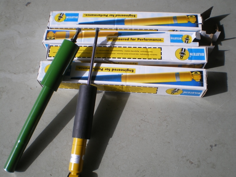 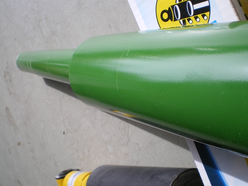 I began with the L front. I had done ball joints/tie rods, brakes, etc. previously so shocks were all that were necessary. The old shock was a blown out KYB which accounted for a noise I heard occasionally. When I dropped the new Bilstein it went 90% in and stopped. The old shock was narrow but this new one is fat and binding. Pulled it out and looked inside and found this bit of rust. 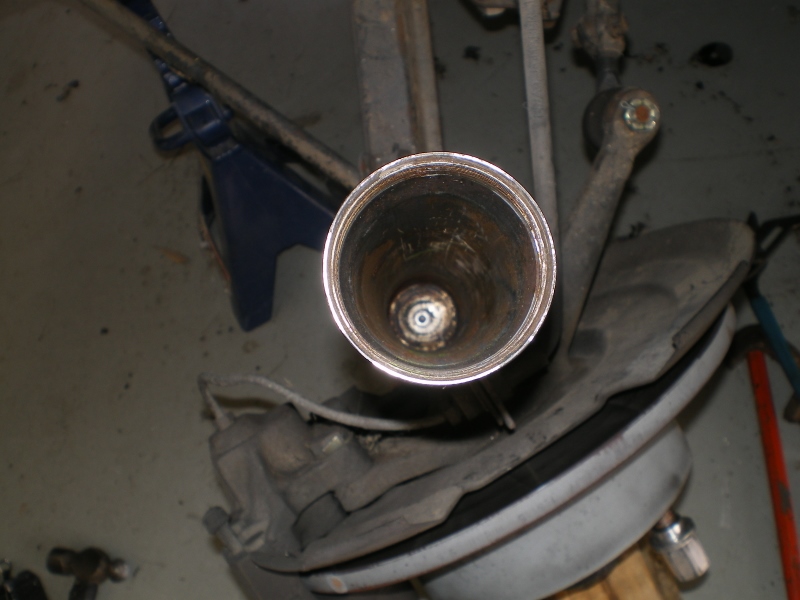 Ran a 2" wire fitting brush thru it several times. I even ran a rotary file over the areas that had rust, in case the metal had raised but it still would not fit. (IMG:style_emoticons/default/stromberg.gif) 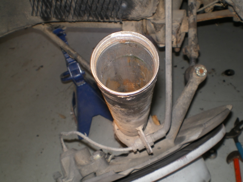 I discovered that area where it bound was the spot where the brake tab is welded on. It probably took a hit there and PO replaced with these skinny shits as a go around. Anyway, my buddy Ethan had these laying around so I cleaned up the L one and I was back in business. 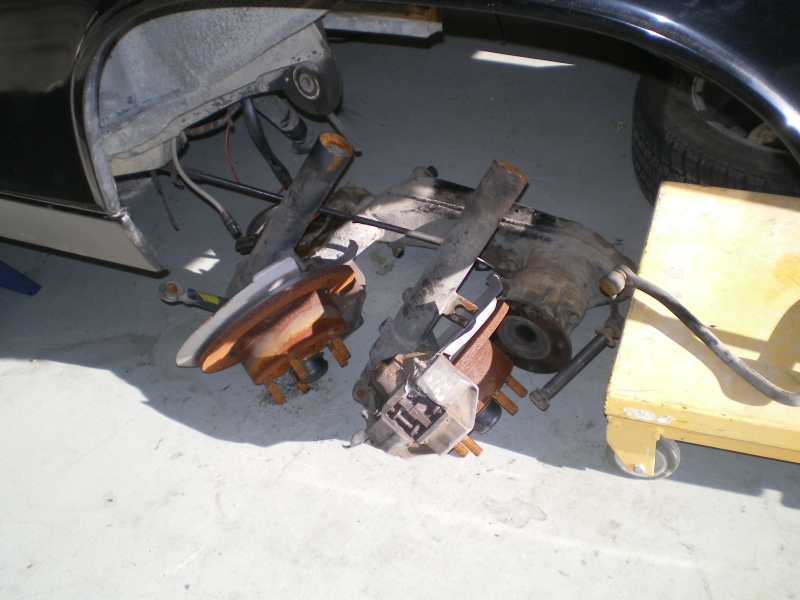 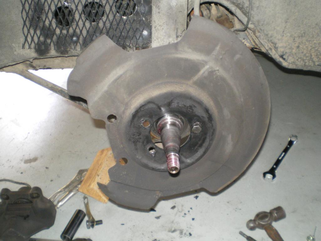 Bought this little tool to aid in refurbishing the trailing arms. 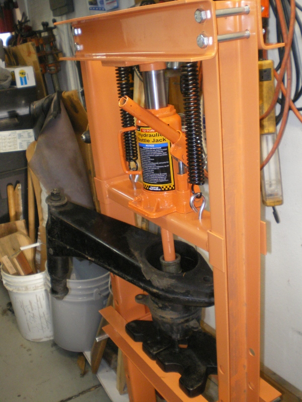 Pressing out the old bearing from the inside. 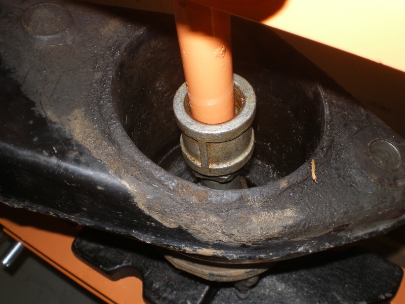 And here it is from the other side exiting the arm. 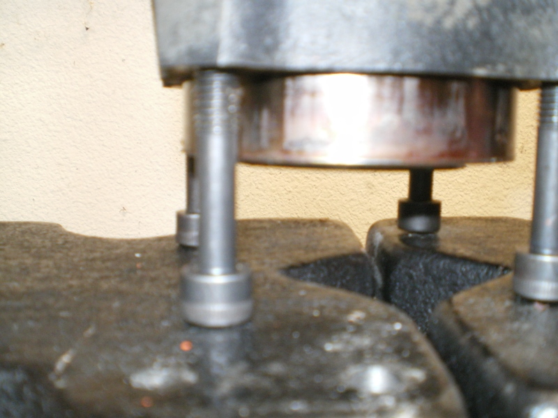 New poly bushings going in 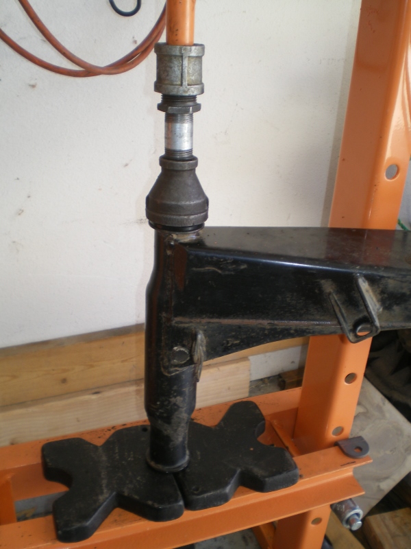 Final assembly of the trailing arm 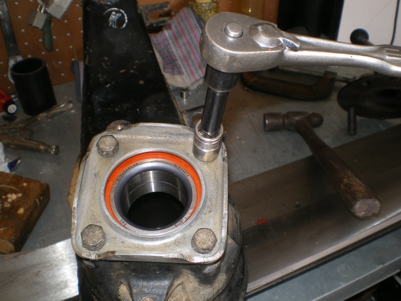 A few installed (less brakes) pics. Rear brake caliper rebuild is next. 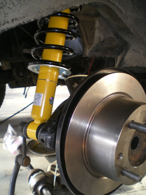 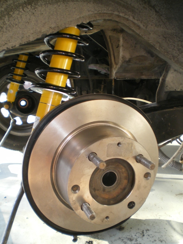 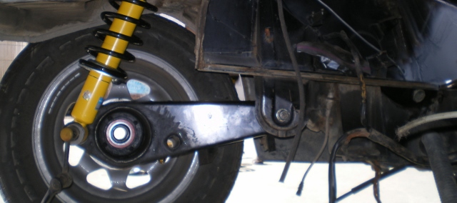 Attached image(s) 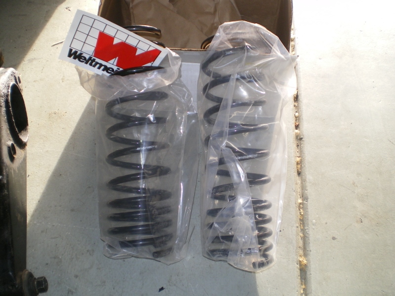 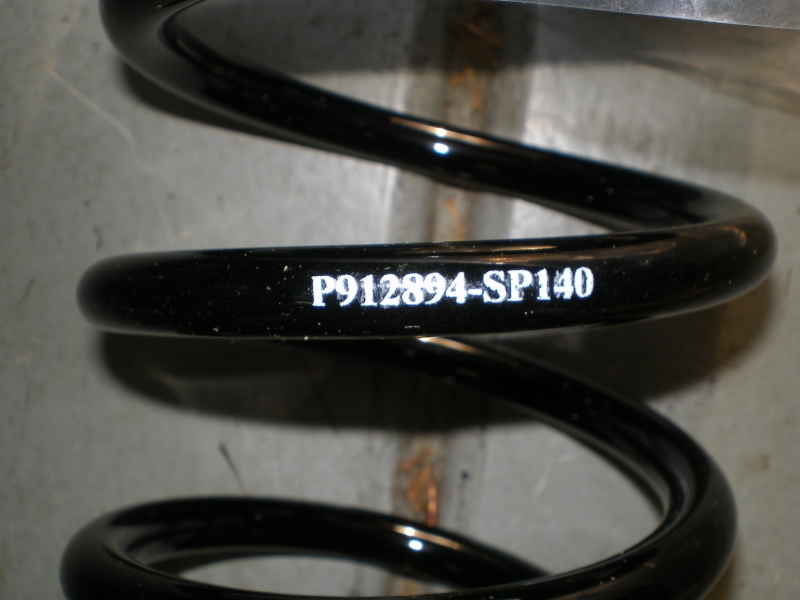
|
| JRust |
 Apr 8 2013, 10:18 PM Apr 8 2013, 10:18 PM
Post
#57
|
|
914 Guru      Group: Members Posts: 6,316 Joined: 10-January 03 From: Albany Oregon Member No.: 129 Region Association: Pacific Northwest 
|
I would not recommend running your radiator lines through the heater ducts int he long. It's great coming from the engine bay. Not so great inside where it goes up & over by the gas tank. Just adds another high spot to your lines. Makes it damn near impossible to get all the air out of the line.
I had considered opening the long inside near the front just before the heater duct goes up. Then adding a small boxed in area at the passenger feet keeping the hose flat & going through right above the steering rack. Just thinking though. I had my lines originally run through the heater ducts. Never got it to cool properly until I ran the lines under the car. I don't love the lines there but it has literally never been a problem with them down there. You progress is looking great |
| 76-914 |
 Apr 9 2013, 08:48 AM Apr 9 2013, 08:48 AM
Post
#58
|
|
Repeat Offender & Resident Subaru Antagonist           Group: Members Posts: 13,694 Joined: 23-January 09 From: Temecula, CA Member No.: 9,964 Region Association: Southern California 
|
Hey Jamie, (IMG:style_emoticons/default/poke.gif) I thought of you last week when my Triton engine blew the spark plug out of #3. (IMG:style_emoticons/default/lol-2.gif) (IMG:style_emoticons/default/hissyfit.gif) I hope that I don't have to run the lines beneath the car but I would if necessary. BTW, I'm going beneath the fuel tank. This might be SOT but I read about these high spots causing a problem because of the air that gets trapped and wondered if this might be a solution in some cases. For 50+ years the Heating and AC trades have used a Hoffman #89 Air Vent to correct this. Most boiler systems and all chill water systems employee these valves. Installed on the high point of any system it will vent out any air in the system, always and automatically. (I might be off one digit on the Hoffman #. It might be a #88. Senility (IMG:style_emoticons/default/sad.gif) ) Sent some more $$$$ to Eric Shea's retirement fund yesterday. (IMG:style_emoticons/default/smash.gif)
|
| AZ914 |
 Apr 9 2013, 09:40 AM Apr 9 2013, 09:40 AM
Post
#59
|
|
914 Dumbass    Group: Members Posts: 1,461 Joined: 6-January 03 From: Sunny Tucson Member No.: 98 Region Association: Southwest Region |
Kent,
Maybe ping member 914GT.. he ran his lines for his Chevy conversion under the car but used iron pipe, so there was no chance of it ripping open. They were ran up the indentations on the floor panel. |
| Chris H. |
 Apr 9 2013, 09:59 AM Apr 9 2013, 09:59 AM
Post
#60
|
|
Senior Member     Group: Members Posts: 4,054 Joined: 2-January 03 From: Chicago 'burbs Member No.: 73 Region Association: Upper MidWest 
|
That was an excellent build! I'm bouncing between that idea and putting the hoses in the longs...Hurry up and find an engine Kent! (IMG:style_emoticons/default/biggrin.gif) (IMG:style_emoticons/default/popcorn[1].gif) (IMG:style_emoticons/default/popcorn[1].gif) (IMG:style_emoticons/default/popcorn[1].gif)
PS - My clutch stuff is coming Thursday. (IMG:style_emoticons/default/aktion035.gif) |
  |
1 User(s) are reading this topic (1 Guests and 0 Anonymous Users)
0 Members:

|
Lo-Fi Version | Time is now: 2nd April 2025 - 02:07 AM |
Invision Power Board
v9.1.4 © 2025 IPS, Inc.


