|
|
|
Porsche, and the Porsche crest are registered trademarks of Dr. Ing. h.c. F. Porsche AG.
This site is not affiliated with Porsche in any way. Its only purpose is to provide an online forum for car enthusiasts. All other trademarks are property of their respective owners. |
|
|

  |

| jd74914 |
 Jun 21 2016, 11:40 PM Jun 21 2016, 11:40 PM
Post
#81
|
|
Its alive  Group: Members Posts: 4,841 Joined: 16-February 04 From: CT Member No.: 1,659 Region Association: North East States |
Sweet! You don't see too many people doing FEA iterations on chassis. (IMG:style_emoticons/default/smilie_pokal.gif)
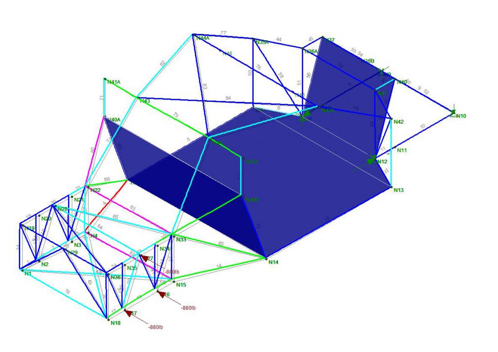
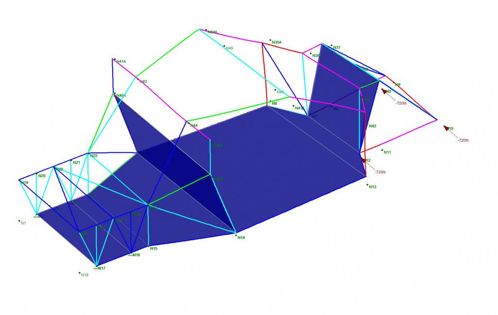
What software package is that? Almost looks like Ansys APDL or maybe more like Grape? You're modeling with beam elements or trusses? Can you glue a shell element floor on to better match reality? In one of the racecars I worked on laminating a thin carbon shear panel on the floors increased stiffness by 25-30% (experimentally verified via twist test too). I think you're seeing artificially high loads in N43A because of the huge open box in the cockpit. If you add triangulation near the doors and closer the floor I bet you'll move some of that load path (if my visual FEA makes any sense haha). Your loading seems a little weird. Why load the lower arms so highly in the vertical direction? They shouldn't see all that much vertical force since it's really all desisted by the spring/damper unit. Why not model the suspension in as an infinitely stiff member and then load with bump, lateral, and longitudinal forces? Then you wouldn't have to draw a free body diagram to figure out point loads. With actual loading N36B might be more heavily loaded than you think (and in some combined weird bending/buckling mode so it probably needs a big safety factor). If you're doing frame stiffness twisting it (via moment about the front suspension nodes with the back fixed) seems more widely accepted than loading one side. There is a good SAE paper on it, I might be able to find it somewhere. Sorry if you know all that stuff already. I'm not a mechanics guy by any means but I've spent a bunch of time doing chassis design/analysis for some tube frame racecars and a Lotus. |
   |

 
|
| Curbandgutter |
Jun 22 2016, 09:44 AM
Post
#82
|
|
Senior Member Group: Members Posts: 565 Joined: 8-March 13 From: Murrieta CA Member No.: 15,637 Region Association: Southern California |
QUOTE(jd74914 @ Jun 21 2016, 10:40 PM)  Sweet! You don't see too many people doing FEA iterations on chassis. (IMG:style_emoticons/default/smilie_pokal.gif) What software package is that? Almost looks like Ansys APDL or maybe more like Grape? You're modeling with beam elements or trusses? Can you glue a shell element floor on to better match reality? In one of the racecars I worked on laminating a thin carbon shear panel on the floors increased stiffness by 25-30% (experimentally verified via twist test too). I think you're seeing artificially high loads in N43A because of the huge open box in the cockpit. If you add triangulation near the doors and closer the floor I bet you'll move some of that load path (if my visual FEA makes any sense haha). Your loading seems a little weird. Why load the lower arms so highly in the vertical direction? They shouldn't see all that much vertical force since it's really all desisted by the spring/damper unit. Why not model the suspension in as an infinitely stiff member and then load with bump, lateral, and longitudinal forces? Then you wouldn't have to draw a free body diagram to figure out point loads. With actual loading N36B might be more heavily loaded than you think (and in some combined weird bending/buckling mode so it probably needs a big safety factor). If you're doing frame stiffness twisting it (via moment about the front suspension nodes with the back fixed) seems more widely accepted than loading one side. There is a good SAE paper on it, I might be able to find it somewhere. Sorry if you know all that stuff already. I'm not a mechanics guy by any means but I've spent a bunch of time doing chassis design/analysis for some tube frame racecars and a Lotus. Now that's what I'm talking about! (IMG:style_emoticons/default/aktion035.gif) (IMG:style_emoticons/default/aktion035.gif) (IMG:style_emoticons/default/aktion035.gif) Love this kind of input. Now to answer some of your questions. The lower A arms were not loaded, what you are seeing is the 3 points where the suspension cradle is bolted to the chassis. The 900 lb vertical load represents a 5g load on the wheel. The next step will be to simultaneously load a 900 lb load in a downward fashion on the opposing suspension cradle support points to create a couple, or rather twisting of the frame as you mentioned. I will be running the same scenario at the rear and then run another scenario to simulate bending forces in the frame. I will go ahead and model the floor and both firewalls with plate elements and see what happens. Might as well model the "longs" as well. this will give a better representation of the behavior. I'm modeling with beam elements with fixed joints in all directions being that the joints will be notched and welded. I would love to get my hands on that SAE paper. I'm sure that I will learn a couple of things. |
|
|
|
| Mueller |
Jun 22 2016, 02:07 PM
Post
#83
|
|
914 Freak! Group: Members Posts: 17,150 Joined: 4-January 03 From: Antioch, CA Member No.: 87 Region Association: None |
Are you going to model the suspension?
If so check out GrabCAD, I got the CV joints and center section from there (I modeled the rest) 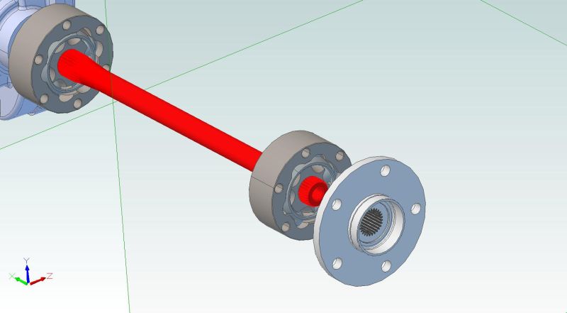 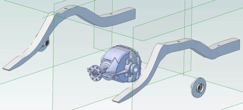 |
|
|
|
| Curbandgutter |
Jun 22 2016, 03:18 PM
Post
#84
|
|
Senior Member Group: Members Posts: 565 Joined: 8-March 13 From: Murrieta CA Member No.: 15,637 Region Association: Southern California |
QUOTE(Mueller @ Jun 22 2016, 01:07 PM) Are you going to model the suspension? If so check out GrabCAD, I got the CV joints and center section from there (I modeled the rest) |
|
|
|
| 914forme |
Jun 22 2016, 03:33 PM
Post
#85
|
|
Times a wastin', get wrenchin'! Group: Members Posts: 3,896 Joined: 24-July 04 From: Dayton, Ohio Member No.: 2,388 Region Association: None |
QUOTE(Curbandgutter @ Jun 22 2016, 05:18 PM) The next item on the list is to build the frame table and to mount the 996 to get all of the suspension pick up points tabulated. Then mount the 914 to start building the chassis with the same suspension pick up points built in. I'll be using a plumb bop and a laser meter to measure and square every thing. It's finally coming together. (IMG:style_emoticons/default/piratenanner.gif) (IMG:style_emoticons/default/piratenanner.gif) (IMG:style_emoticons/default/popcorn[1].gif) Hoping it is built with I beams and 1/2" plate, so you can weld to it. In reality the I beams are fine, you should make the plate float on individual sections. So you can level the plate separate of the frame. So it looks kinda like this on a much larger scale. 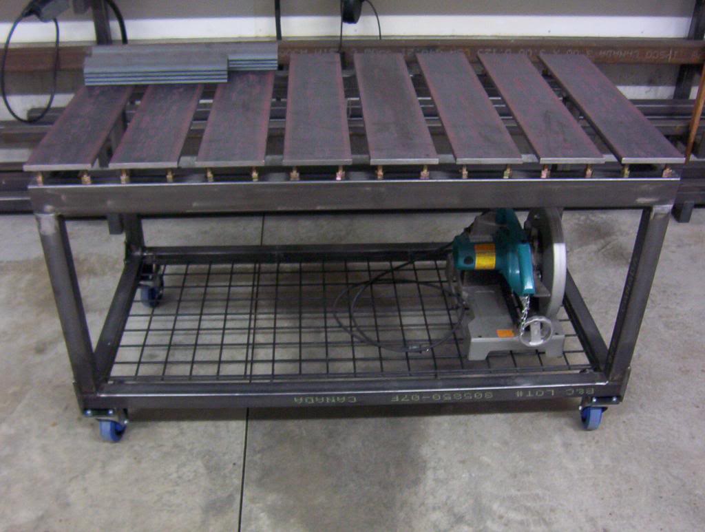 Not mine but highly admired from the Garage Journal Forum. |
|
|
|
| Curbandgutter |
Jun 22 2016, 05:35 PM
Post
#86
|
|
Senior Member Group: Members Posts: 565 Joined: 8-March 13 From: Murrieta CA Member No.: 15,637 Region Association: Southern California |
I am making it out of 4x4 tubing. The tubing has much tighter mill tolerances than hot rolled I-beams. Also square tubing is much better than an I-beam in torsion. To make it out of an I-beam I would have to have it blanchard ground. I'm going with 4x4x3/16 frame with six 4x4x3/16 legs. All cross braced with 4 casters and 6 leveling screws. I'll tack weld on the ground enough so that I can raise and assemble. Then I will level all six legs with my survey equipment. Once leveled I will continue welding all seams a little at a time and from opposing corners so that the table does not warp. Then I will finish in that same Hunter Green as the rotisserie. That small chassis table looks like it's awesome for small projects though.
|
|
|
|
| Curbandgutter |
Jun 22 2016, 06:02 PM
Post
#87
|
|
Senior Member Group: Members Posts: 565 Joined: 8-March 13 From: Murrieta CA Member No.: 15,637 Region Association: Southern California |
QUOTE(Curbandgutter @ Jun 22 2016, 04:35 PM) I am making it out of 4x4 tubing. The tubing has much tighter mill tolerances than hot rolled I-beams. Also square tubing is much better than an I-beam in torsion. To make it out of an I-beam I would have to have it blanchard ground. I'm going with 4x4x3/16 frame with six 4x4x3/16 legs. All cross braced with 4 casters and 6 leveling screws. I'll tack weld on the ground enough so that I can raise and assemble. Then I will level all six legs with my survey equipment. Once leveled I will continue welding all seams a little at a time and from opposing corners so that the table does not warp. Then I will finish in that same Hunter Green as the rotisserie. That small chassis table looks like it's awesome for small projects though. Attached image(s) 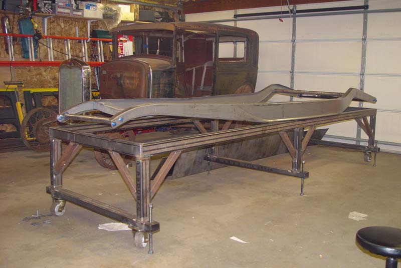
|
|
|
|
| jd74914 |
Jun 22 2016, 09:58 PM
Post
#88
|
|
Its alive Group: Members Posts: 4,841 Joined: 16-February 04 From: CT Member No.: 1,659 Region Association: North East States |
QUOTE(Curbandgutter @ Jun 22 2016, 10:44 AM) Now that's what I'm talking about! (IMG:style_emoticons/default/aktion035.gif) (IMG:style_emoticons/default/aktion035.gif) (IMG:style_emoticons/default/aktion035.gif) Love this kind of input. Now to answer some of your questions. The lower A arms were not loaded, what you are seeing is the 3 points where the suspension cradle is bolted to the chassis. The 900 lb vertical load represents a 5g load on the wheel. The next step will be to simultaneously load a 900 lb load in a downward fashion on the opposing suspension cradle support points to create a couple, or rather twisting of the frame as you mentioned. I will be running the same scenario at the rear and then run another scenario to simulate bending forces in the frame. I will go ahead and model the floor and both firewalls with plate elements and see what happens. Might as well model the "longs" as well. this will give a better representation of the behavior. I'm modeling with beam elements with fixed joints in all directions being that the joints will be notched and welded. I would love to get my hands on that SAE paper. I'm sure that I will learn a couple of things. (IMG:style_emoticons/default/beerchug.gif) I get worried that people will take offense to comments like those sometimes. Gotcha, I just looked at your pictures again; didn't realize the 996 stuff was all on a subframe. Now it all makes sense. Looking at that model again it might get stiffer if you switch from the bent front windshield frame halo-style bar rearward facing bars like found in a non-halo cage. Then you'd spread the longitudinal bars (N44 and N43 maybe) out towards the edges moving them further from your head and building a better node at the windshield corners. I just get scared seeing cross-bracing put hoops in bending. It might also be worth switching around some of the triangulation (ie: in front of and behind the door) to meeting at the same places to form some "super nodes." I noticed on the full tube chassis that this seemed to help stiffness without any weight penalty. The x-bracing on top and bottom of the rear might make maintenance very difficult. I did this over a chain drive differential in the name of stiffness and really hated myself for it after the fact. You could probably get most of the stiffness with a bolted shear panel. Hopefully that makes some sense; I can draw it tomorrow really quickly too. The 5g load is pretty conservative; I've always designed around 3g bump, 2g lateral, and 2g longitudinal loading (though not all at the same time since tire friction circles limit the combined grip) and haven't had many problems. Your analysis plan sounds good to me! Unfortunately I'm at a conference right now and having trouble remoting into my regular computer to look but I'll check for the paper as soon as I get home. Totally unrelated to the design stuff, but when you notch everything be sure to drill small holes in all of the receiving tubes at the joints. Being able to back purge while welding makes the whole process much better. You have less problems with oils, etc. running out and end up with much higher quality welds. (IMG:style_emoticons/default/smile.gif) |
|
|
|
| Curbandgutter |
Jun 23 2016, 10:30 AM
Post
#89
|
|
Senior Member Group: Members Posts: 565 Joined: 8-March 13 From: Murrieta CA Member No.: 15,637 Region Association: Southern California |
Thank You JD. I appreciate your excellent input.
|
|
|
|
| Curbandgutter |
Jun 23 2016, 08:01 PM
Post
#90
|
|
Senior Member Group: Members Posts: 565 Joined: 8-March 13 From: Murrieta CA Member No.: 15,637 Region Association: Southern California |
2g Lateral Load at rear yields a 1/16" lateral deflection
 3g Couple at rear yields a 0.114 vertical deflection 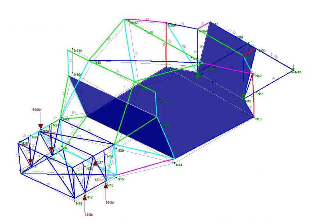 3g Couple at front yields a 0.10" vertical deflection 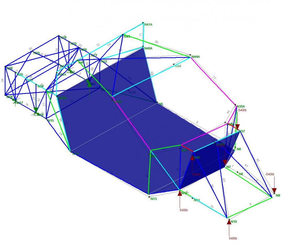 2g Lateral in front yields a WHOPPING 0.70" lateral defelction. This is the worst case. It makes sense too in that the hole where the engine is allows this deflection. I'll have to fix that somehow. I have to wait until the motor is in to add a removable cross brace or just live with it. We will see. 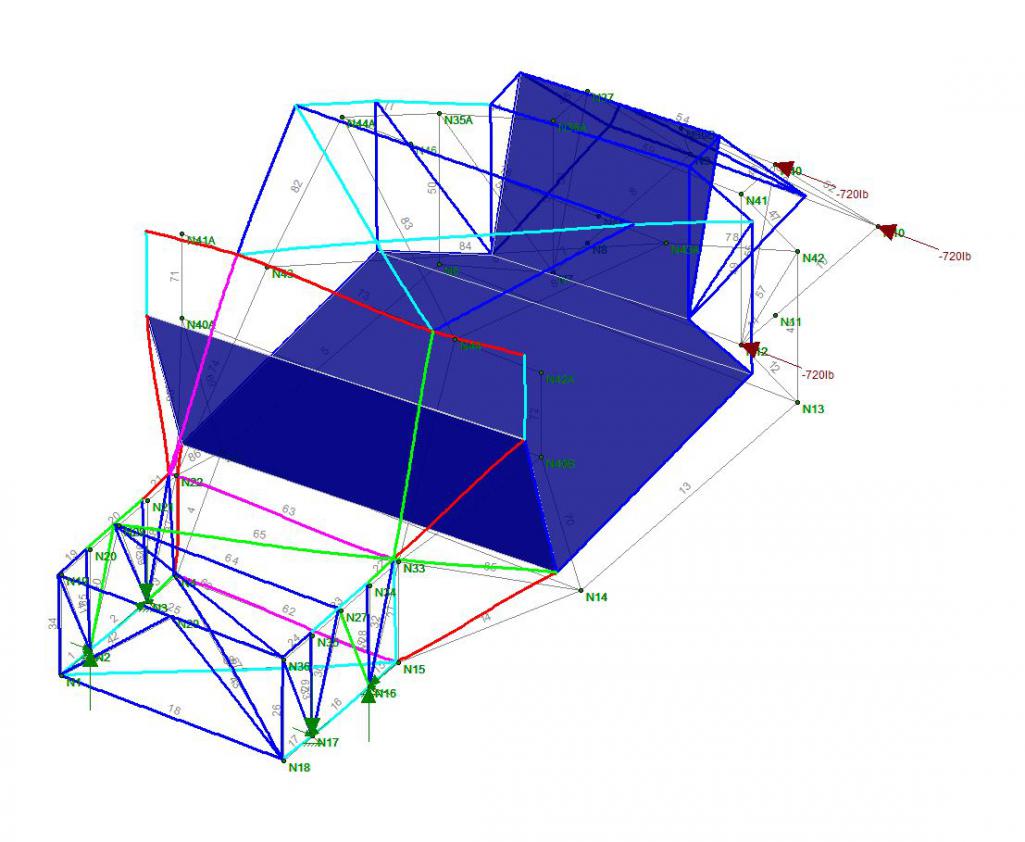 |
|
|
|
| Curbandgutter |
Jun 23 2016, 08:05 PM
Post
#91
|
|
Senior Member Group: Members Posts: 565 Joined: 8-March 13 From: Murrieta CA Member No.: 15,637 Region Association: Southern California |
I'm feeling pretty good about this chassis (IMG:style_emoticons/default/cheer.gif) (IMG:style_emoticons/default/cheer.gif) (IMG:style_emoticons/default/cheer.gif) .
|
|
|
|
| jd74914 |
Jun 23 2016, 10:08 PM
Post
#92
|
|
Its alive Group: Members Posts: 4,841 Joined: 16-February 04 From: CT Member No.: 1,659 Region Association: North East States |
QUOTE(Curbandgutter @ Jun 23 2016, 09:01 PM) 2g Lateral Load at rear yields a 1/16" lateral deflection 3g Couple at rear yields a 0.114 vertical deflection 3g Couple at front yields a 0.10" vertical deflection 2g Lateral in front yields a WHOPPING 0.70" lateral defelction. This is the worst case. It makes sense too in that the hole where the engine is allows this deflection. I'll have to fix that somehow. I have to wait until the motor is in to add a removable cross brace or just live with it. We will see. Nice! Those numbers look great! (IMG:style_emoticons/default/beerchug.gif) If you have time it might be interesting to run a case with a bunch of tubes connecting the rough engine mount locations into one node. At least it'd give you some idea of how much deflection the engine stops (assuming it's not super softly mounted). I bet with an "engine" surrogate in there you'd get a lot of the 0.70" back without making any other changes. Adding a bolt-on stressed panel under the engine (could double as a belly pan for aero) would bring back a bunch of stiffness too. Two pure curiosity questions...How much does it weigh? What software are you using for FEA? |
|
|
|
| Curbandgutter |
Jun 24 2016, 11:52 AM
Post
#93
|
|
Senior Member Group: Members Posts: 565 Joined: 8-March 13 From: Murrieta CA Member No.: 15,637 Region Association: Southern California |
That did it. Since the lower frame is flush with the bottom pan of the car. I can bolt on a plate along the bottom and it totally fixed the flex. The flex now is 0.1" as opposed to 0.7"! I like the way you think. (IMG:style_emoticons/default/beerchug.gif) (IMG:style_emoticons/default/beerchug.gif) The bottom plate will also blend into a rear diffuser. I am planning on exiting my exhaust above the rear bumper line.
 With regard to weight it will add about 150 lbs. However, the front and rear hood, and the front and rear bumpers will be fiberglass. I'm going with about 600 HP (IMG:style_emoticons/default/av-943.gif) so the extra weight will not be a distraction. |
|
|
|
| jd74914 |
Jun 27 2016, 09:09 AM
Post
#94
|
|
Its alive Group: Members Posts: 4,841 Joined: 16-February 04 From: CT Member No.: 1,659 Region Association: North East States |
QUOTE(Curbandgutter @ Jun 24 2016, 12:52 PM) That did it. Since the lower frame is flush with the bottom pan of the car. I can bolt on a plate along the bottom and it totally fixed the flex. The flex now is 0.1" as opposed to 0.7"! (IMG:style_emoticons/default/beerchug.gif) Fantastic! Easy fix! My guess is that you will retain nearly all of the added rigidity even if you have to cut some holes in it for access to things like oil filters, etc. The weight doesn't seem bad at all, especially considering that you are cutting out existing structure and using some glass parts. Is this design using different diameter/wall thickness tubing? |
|
|
|
| Curbandgutter |
Jun 27 2016, 04:51 PM
Post
#95
|
|
Senior Member Group: Members Posts: 565 Joined: 8-March 13 From: Murrieta CA Member No.: 15,637 Region Association: Southern California |
It uses thick tubing for the main hoops and thinner everywhere I can.
|
|
|
|
| Curbandgutter |
Jun 27 2016, 04:56 PM
Post
#96
|
|
Senior Member Group: Members Posts: 565 Joined: 8-March 13 From: Murrieta CA Member No.: 15,637 Region Association: Southern California |
Well the material came in for the the chassis table.
These are the 2x2's that I will use for the webs 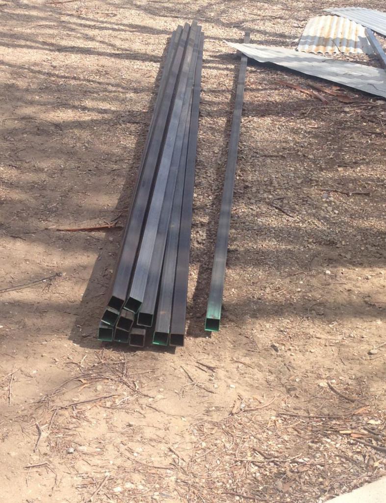 These are the 4x4's that I will use for the table platform and legs 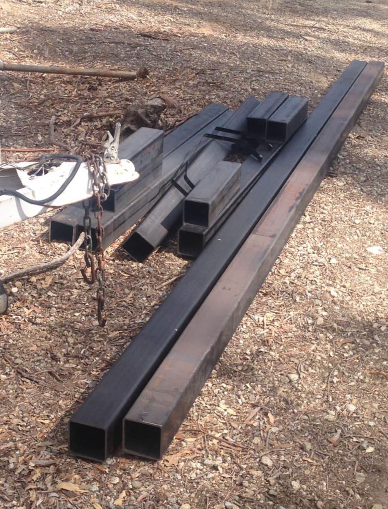 Here are the casters 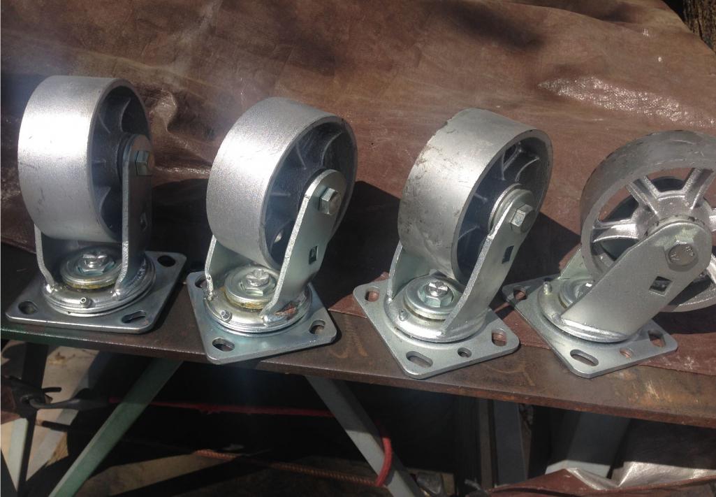 I also picked up some samples of Fine, Medium and Coarse recycled glass for the wet sandblasting. I'll try each to see which works better. Planning on blasting the suspension clean as well. I'll probably be using the fine for the aluminum blasting. I know guys use glass beads for aluminum but that is for delicate surfaces. The suspension is hardly a delicate surface so we will see how it pans out. 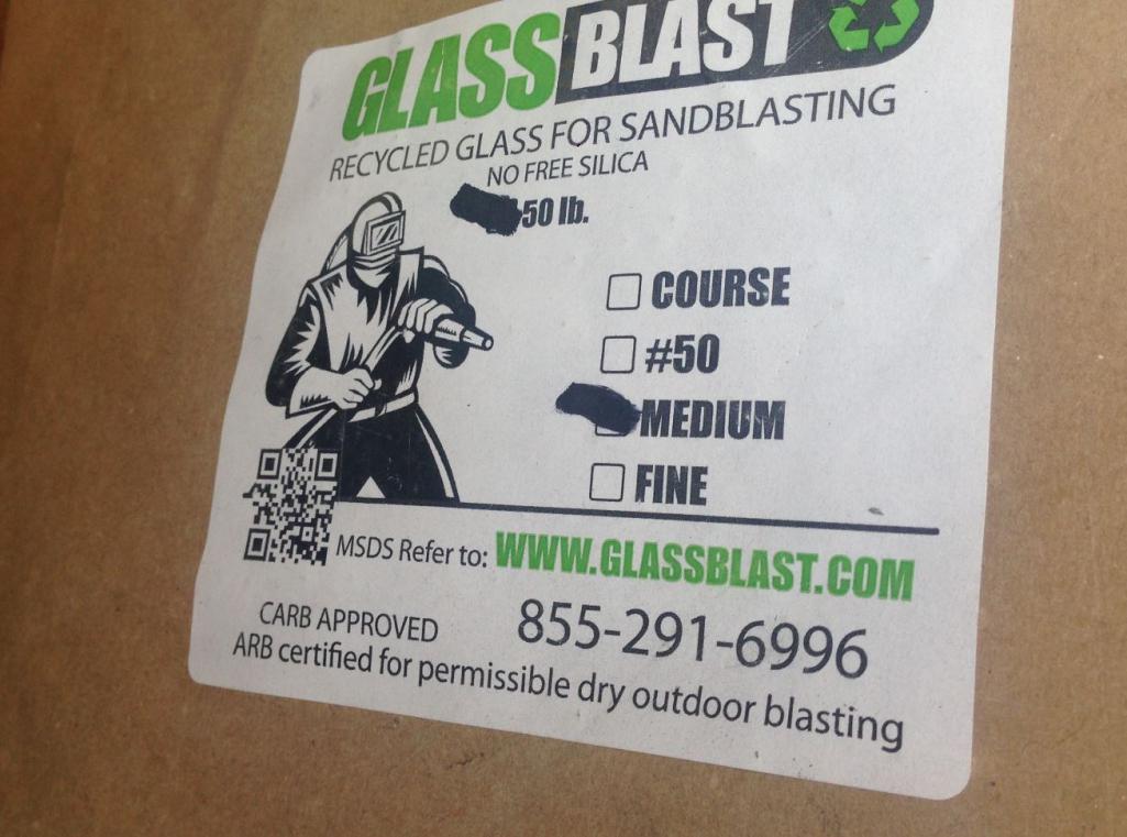 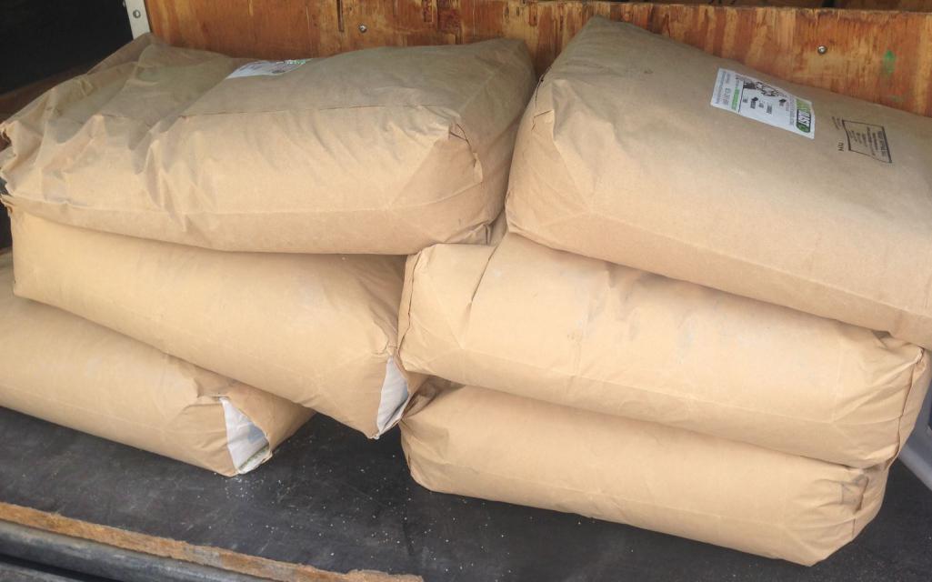 |
|
|
|
| 76-914 |
Jun 27 2016, 06:12 PM
Post
#97
|
|
Repeat Offender & Resident Subaru Antagonist Group: Members Posts: 13,698 Joined: 23-January 09 From: Temecula, CA Member No.: 9,964 Region Association: Southern California |
Hey Rudy, I almost stopped by today but then I thought I should first ask if your around during the day. I might still be cleaning my engine Saturday. If I do finish cleaning it by then I'll start bolting the engine back together. I'll let you know when that begins.
That's a lot of metal there. But then again your connected in the welding biz, right? |
|
|
|
| Curbandgutter |
Jun 27 2016, 06:35 PM
Post
#98
|
|
Senior Member Group: Members Posts: 565 Joined: 8-March 13 From: Murrieta CA Member No.: 15,637 Region Association: Southern California |
No more connections. We used to be in the industry 30 years ago. Now the only connection you need is the green kind. Damn steel is crazy expensive. (IMG:style_emoticons/default/hissyfit.gif) (IMG:style_emoticons/default/hissyfit.gif) (IMG:style_emoticons/default/hissyfit.gif) The material was around $1,200 (IMG:style_emoticons/default/barf.gif) I'm usually in the office, so if you're by the area come on by.
|
|
|
|
| jd74914 |
Jun 27 2016, 07:00 PM
Post
#99
|
|
Its alive Group: Members Posts: 4,841 Joined: 16-February 04 From: CT Member No.: 1,659 Region Association: North East States |
QUOTE(Curbandgutter @ Jun 27 2016, 05:51 PM) It uses thick tubing for the main hoops and thinner everywhere I can. Cool! Figured you must be given the weight. I love 0.035 wall tubing! (IMG:style_emoticons/default/biggrin.gif) (IMG:style_emoticons/default/blink.gif) (IMG:style_emoticons/default/drooley.gif) QUOTE(Curbandgutter @ Jun 27 2016, 07:35 PM) No more connections. We used to be in the industry 30 years ago. Now the only connection you need is the green kind. Damn steel is crazy expensive. (IMG:style_emoticons/default/hissyfit.gif) (IMG:style_emoticons/default/hissyfit.gif) (IMG:style_emoticons/default/hissyfit.gif) The material was around $1,200 (IMG:style_emoticons/default/barf.gif) Ouch. (IMG:style_emoticons/default/headbang.gif) Can't wait to see the cart put together! |
|
|
|
| Chris914n6 |
Jun 27 2016, 08:54 PM
Post
#100
|
|
Jackstands are my life. Group: Members Posts: 3,461 Joined: 14-March 03 From: Las Vegas, NV Member No.: 431 Region Association: Southwest Region |
QUOTE(Curbandgutter @ Jun 21 2016, 02:43 PM) Sorry, I'm a little late to the party (IMG:style_emoticons/default/smile.gif) Looks like a NASCAR chassis, which would be a good reference. Hard to see numbers with my eyes, but you will need bars at n14-n15 and in the front n13-n06 and n12-n07, or your first t-bone will be your last anything. |
|
|
|
|
1 User(s) are reading this topic (1 Guests and 0 Anonymous Users)
0 Members:

|
Lo-Fi Version | Time is now: 19th April 2025 - 02:53 AM |
Invision Power Board
v9.1.4 © 2025 IPS, Inc.