|
|

|
Porsche, and the Porsche crest are registered trademarks of Dr. Ing. h.c. F. Porsche AG.
This site is not affiliated with Porsche in any way. Its only purpose is to provide an online forum for car enthusiasts. All other trademarks are property of their respective owners. |
|
|
  |
| mfor1000 |
 Nov 23 2024, 07:53 AM Nov 23 2024, 07:53 AM
Post
#381
|
|
Newbie  Group: Members Posts: 20 Joined: 26-July 22 From: Mooresville, NC Member No.: 26,718 Region Association: South East States |
Hi everyone, Matt here—Jerry’s son. Since the day I bought this car, it’s been an endless source of entertainment and technical challenges, and I’ve loved every minute of it. This car deserves the best, so I decided to embark on a major driveline and electrical upgrade. Buckle up, because this one’s a ride!
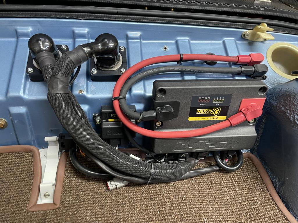
First up: the Electromotive ECU. Let’s be honest—it was great in its time, but it’s like comparing a flip phone to a smartphone. So, I treated the car to a cutting-edge Haltech R3. This ECU is a total game-changer. It has a built in PDM so it can manage the fuel pump, ignition, injectors, and even the auxiliary oil cooler fan directly. Translation? No more clunky relays, and everything is controlled with precision. And here’s the best part: I can connect to it over WiFi and monitor or tune it straight from my phone. I still use the PC for most of it, but that is handy for minor tuning! Oh, and why not make it drive by wire? Who says classic cars can’t live in the future? Next on the list: the gearbox. While the engine is a masterpiece, the original 901 gearbox was… well, not. I considered upgrading to a 915, but side-shift versions are as rare as unicorns, and to be honest, I wasn’t impressed when I drove one. Maybe it was a bad example, but the shifts felt slow and uninspiring. So, I went bold and decided to adapt an 012 5-speed gearbox from an early Boxster. It’s a fantastic modern gearbox, and while most use cables for shifting, I opted for the Audi version with a shaft mechanism to preserve that crisp, direct feel. Of course, swapping this gearbox into an early 911 isn’t exactly plug-and-play. Here’s what I was up against:
(I'm not really this good of a writer, but chatGPT sure is...) 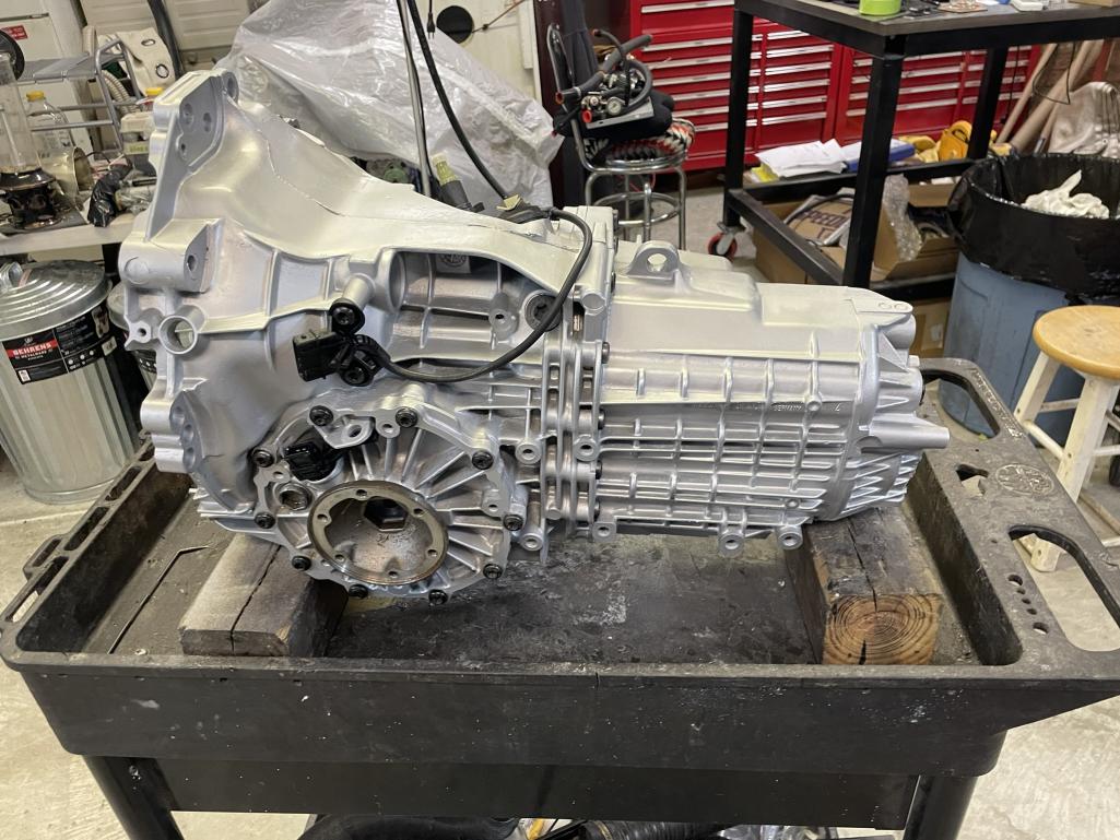 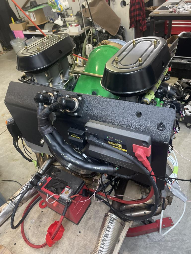 |
| Cairo94507 |
 Nov 23 2024, 08:03 AM Nov 23 2024, 08:03 AM
Post
#382
|
|
Michael           Group: Members Posts: 10,093 Joined: 1-November 08 From: Auburn, CA Member No.: 9,712 Region Association: Northern California 
|
(IMG:style_emoticons/default/welcome.png) Nice introduction and plan. Looking forward to watching this all come together. And you are doing this in an early 911, right? (IMG:style_emoticons/default/beerchug.gif)
|
| mfor1000 |
 Nov 23 2024, 08:23 AM Nov 23 2024, 08:23 AM
Post
#383
|
|
Newbie  Group: Members Posts: 20 Joined: 26-July 22 From: Mooresville, NC Member No.: 26,718 Region Association: South East States |
Unfortunately, I didn’t take many pictures while creating the wiring harness for the Haltech Nexus R3. Trust me, though—it was a serious project that consumed about a month of weekends. I went for a semi-motorsports-level harness, using Raychem DR-25 sleeving and TE Connectivity boots where I could. Why “semi” motorsports? I stuck with Deutsch and OEM-style connectors instead of going all-in with autosport connectors. Full autosport setups would’ve required all-Tefzel wiring, but honestly, that felt like overkill for this build. Sure, Tefzel would’ve shaved off a pound or two, but this isn’t a race car, and reliability is my top priority.
The result? A robust, reliable harness that should stand the test of time. The setup includes two wideband sensors and two knock sensors, plus a drive-by-wire system that uses an E36 M3 throttle actuator. It has a built-in TPS (Throttle Position Sensor) and an additional TPS on the PMO injector. These two constantly compare data to ensure there’s no malfunction—redundancy for the win! To make life easier, I bought an engine-running stand from Amazon (seriously, how cool is it that you can just buy one of these on Amazon?), then welded up adapters to match the 914 engine and transmission mounts. For now, I used the 901 transmission just to keep everything in place. This stand turned out to be a game-changer because I wanted to sort out the starting and no-load running of the engine before heading to the dyno. And boy, was I glad I did. I ran into some headaches with the cam sensor phasing. The Haltech is particular about the cam sensor being in a specific window relative to the crank sensor, and troubleshooting that would’ve been a nightmare with the engine already in the car. On the stand, though? Piece of cake (well, mostly). I also was able to go through each sensor and make sure it was reading correctly. I had a few errors...as always, but again how nice it was to do it outside the car! Once I had it running, I started it cold every morning for a few weekends, dialing in the cold start parameters. It was so satisfying to tweak it, start it again, and see the improvements. By the time it’s ready for the dyno, the engine will already be in a great spot. 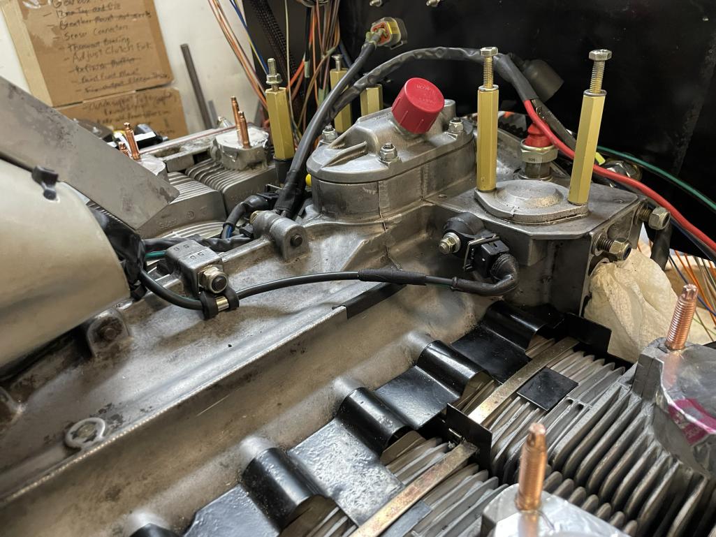 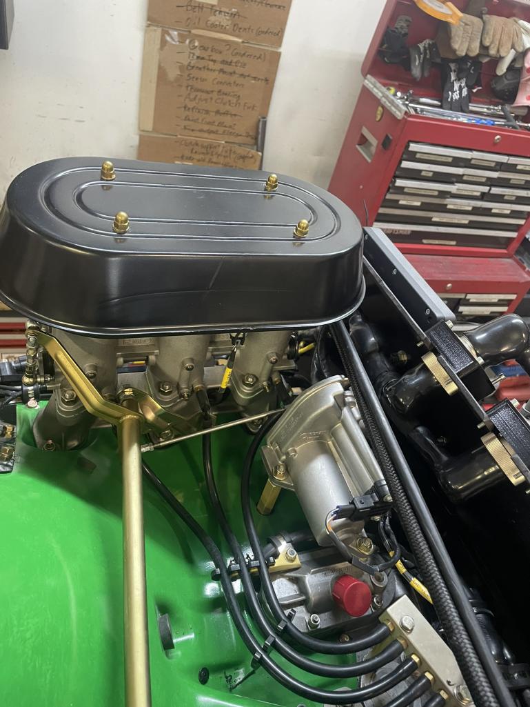 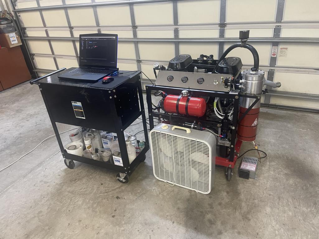 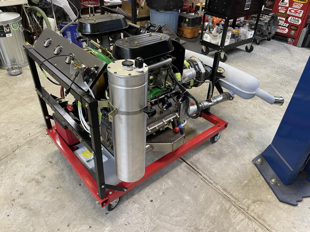 Here is a video of the throttle actuator working (a happy day!): Throttle Actuator Video |
| mfor1000 |
 Nov 23 2024, 08:34 AM Nov 23 2024, 08:34 AM
Post
#384
|
|
Newbie  Group: Members Posts: 20 Joined: 26-July 22 From: Mooresville, NC Member No.: 26,718 Region Association: South East States |
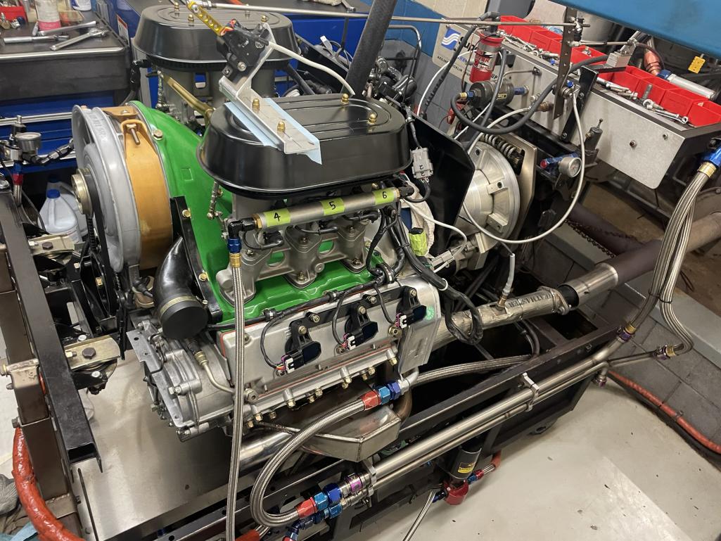
Next stop: the dyno! I borrowed a truck and hauled the engine over to my friend’s engine shop, which is equipped with a proper dyno. My friend usually tunes race engines for local short tracks, so his setup was perfect for this kind of testing.
To adapt the 911 engine to his dyno, I had to get creative. I designed an adapter in CAD to mate the 911 engine to a Chevy bellhousing—an easy solution for his dyno configuration. Once I finished the design, I uploaded it to SendCutSend, and by the next weekend, the adapter was sitting in my hands. Total cost? About $90. It’s incredible what you can achieve with modern fabrication services! The dyno session was a blast. We spent the day running steady-state tests and making pulls at different load levels to dial everything in. The Haltech ECU was a dream to work with—super intuitive and easy to tune. By the end of the day, the engine made 289 hp at around 7,000 rpm and was still pulling strong. Supposedly, the valvetrain can handle up to 8,000 rpm, but since this isn’t a race car, I didn’t see much point in pushing it that far. Still, 289 hp in a 2,100-pound car should feel pretty lively. 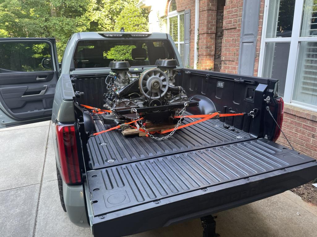 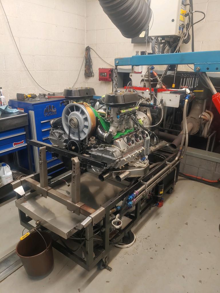 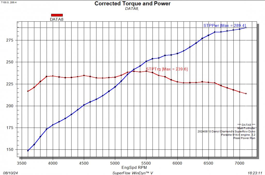 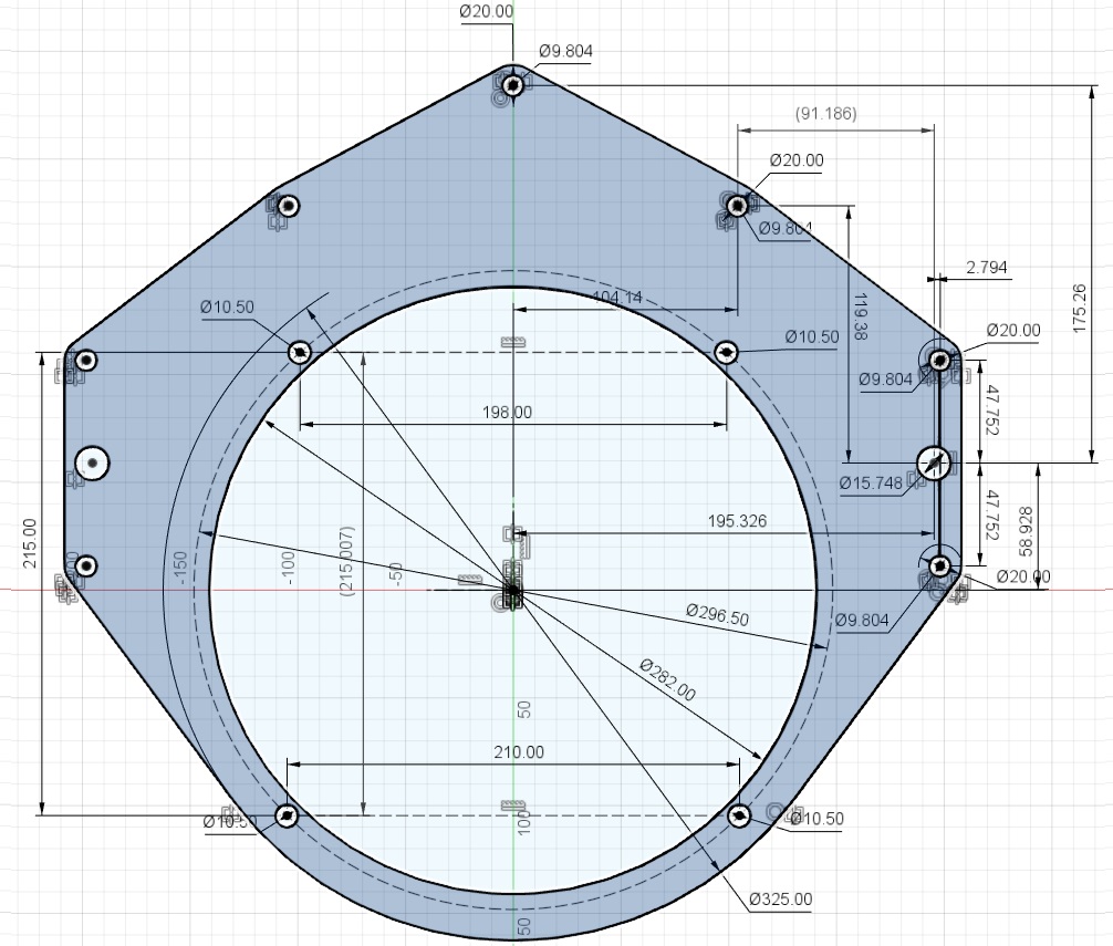 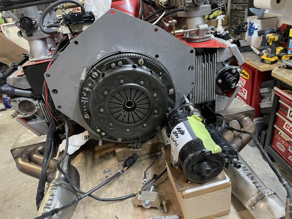 |
| mfor1000 |
 Nov 23 2024, 08:44 AM Nov 23 2024, 08:44 AM
Post
#385
|
|
Newbie  Group: Members Posts: 20 Joined: 26-July 22 From: Mooresville, NC Member No.: 26,718 Region Association: South East States |
|
| mfor1000 |
 Nov 23 2024, 08:52 AM Nov 23 2024, 08:52 AM
Post
#386
|
|
Newbie  Group: Members Posts: 20 Joined: 26-July 22 From: Mooresville, NC Member No.: 26,718 Region Association: South East States |
You might have noticed the change in the shroud’s color… there’s a bit of a story behind that. The original paint kept chipping, so I decided to sand it down. As I worked, I discovered that this shroud has lived many lives—it had been painted several different colors over the years!
At one point during sanding, it had this wild tie-dye look, and I was honestly tempted to leave it that way. But in the end, I decided to keep going until I reached the original green gel coat underneath. The result is a cool, marbled appearance that I really like. Interestingly, this green seems to match the correct shroud color for the engine’s origins—a 1977 3.0 Carrera base. It’s a nice nod to the engine’s history while giving it a fresh and unique look. 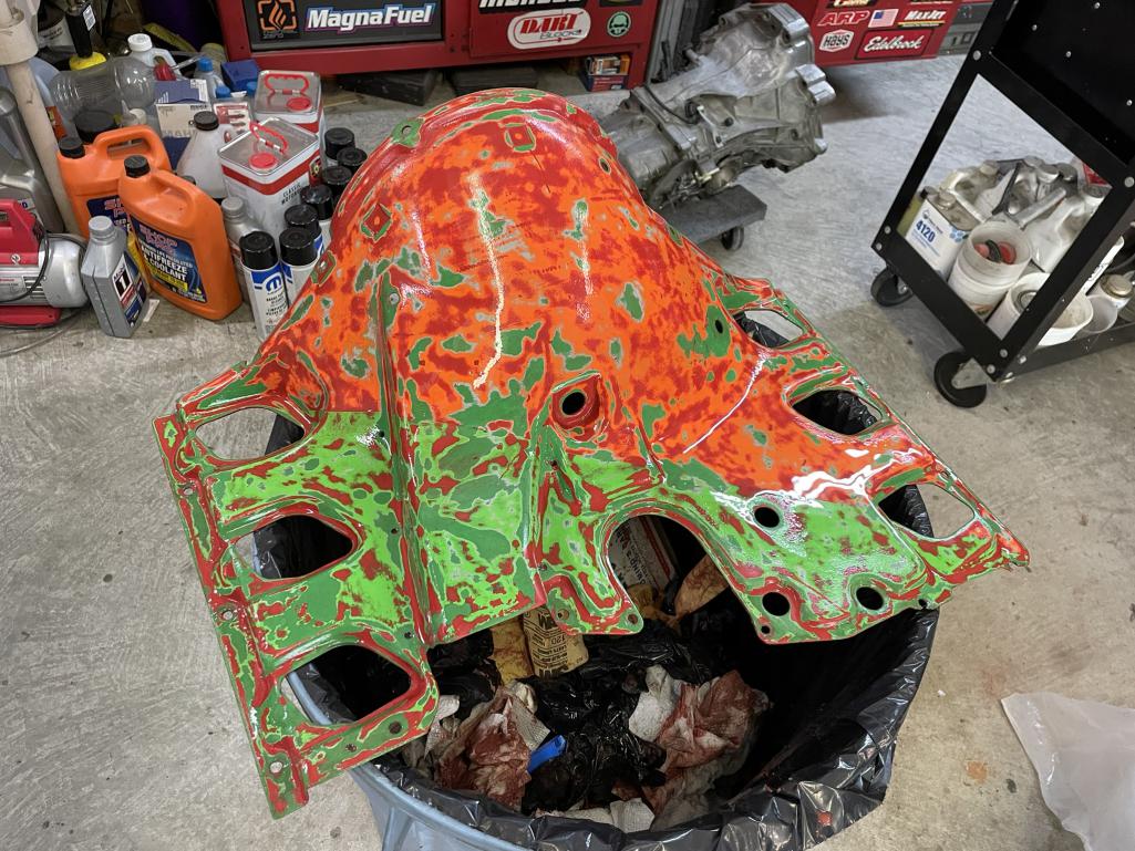 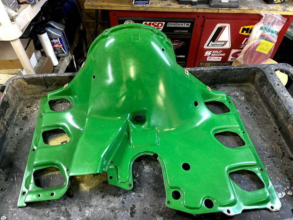 |
| mfor1000 |
 Nov 23 2024, 09:41 AM Nov 23 2024, 09:41 AM
Post
#387
|
|
Newbie  Group: Members Posts: 20 Joined: 26-July 22 From: Mooresville, NC Member No.: 26,718 Region Association: South East States |
On to the transmission...The first challenge was to create an adapter that goes from the 911 engine to the 012 bellhousing. So I bought some giant digital calipers and spent a bunch of time measuring. Since there will be a certain amount of error in this, I 3D printed it a couple times to get it dialed in. Then I uploaded it to send cut send and got one cut out of acrylic. Still another could of adjustments and I ordered one from them made from 1/2" 6061 aluminum. It is a little tricky because I needed to step it up past the oil cooler on the driver's side.
According to my measurements, the input shaft on the 901 transmission sticks out 10mm past the face of the bellhousing. The 012 transmission has the input shaft recessed by 9 mm relative to that surface. This means you have to cut 19mm plus the thickness of the adapter plate off the bellhousing of the 012 transmission. (31.7 mm). I did this and leveled it out using a dial guage to within 0.005" relative to the input shaft by hand. I also cut the hole for the starter and its adapter. 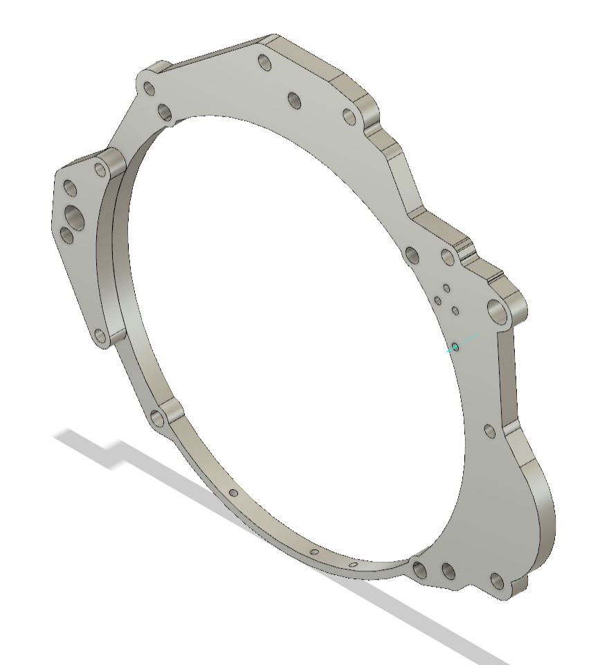 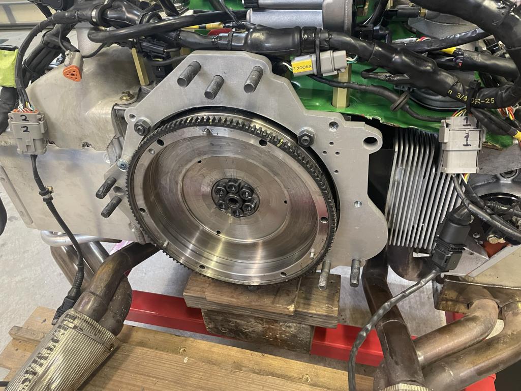 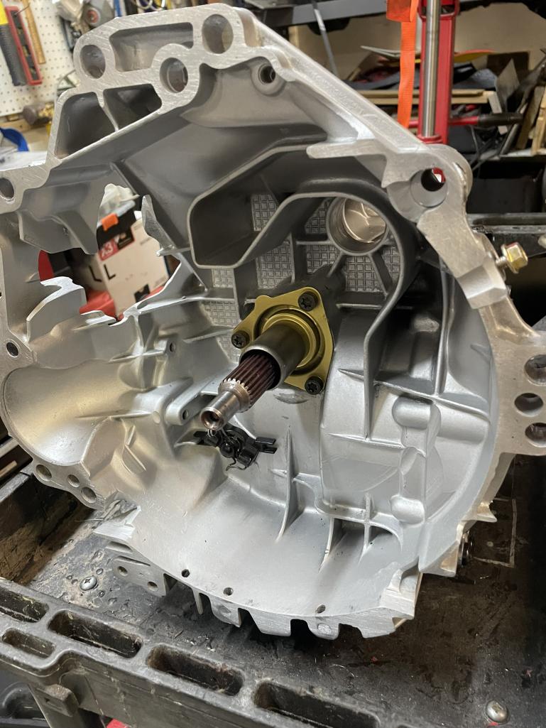 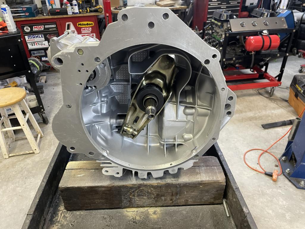 Attached thumbnail(s) 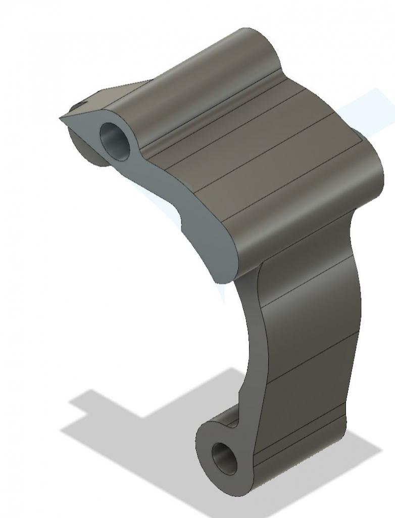
|
| mfor1000 |
 Nov 23 2024, 09:48 AM Nov 23 2024, 09:48 AM
Post
#388
|
|
Newbie  Group: Members Posts: 20 Joined: 26-July 22 From: Mooresville, NC Member No.: 26,718 Region Association: South East States |
Here are a couple more pictures of the starter mount I designed. I had it CNC-cut by PCBWay, and they did a fantastic job. One small tweak I had to make was adding a rubber hose to the vent, as the original vent would’ve hit the starter. To finish it off, I picked up a 5/16 diff vent from Amazon to fit into the hose—simple and effective.
In the second picture, you can clearly see the shifter input shaft. Connecting that to the shifter shaft coming out of the firewall is going to be an interesting challenge for the future. I’ve already got some ideas brewing, but it’s definitely one of the trickier parts of this project! 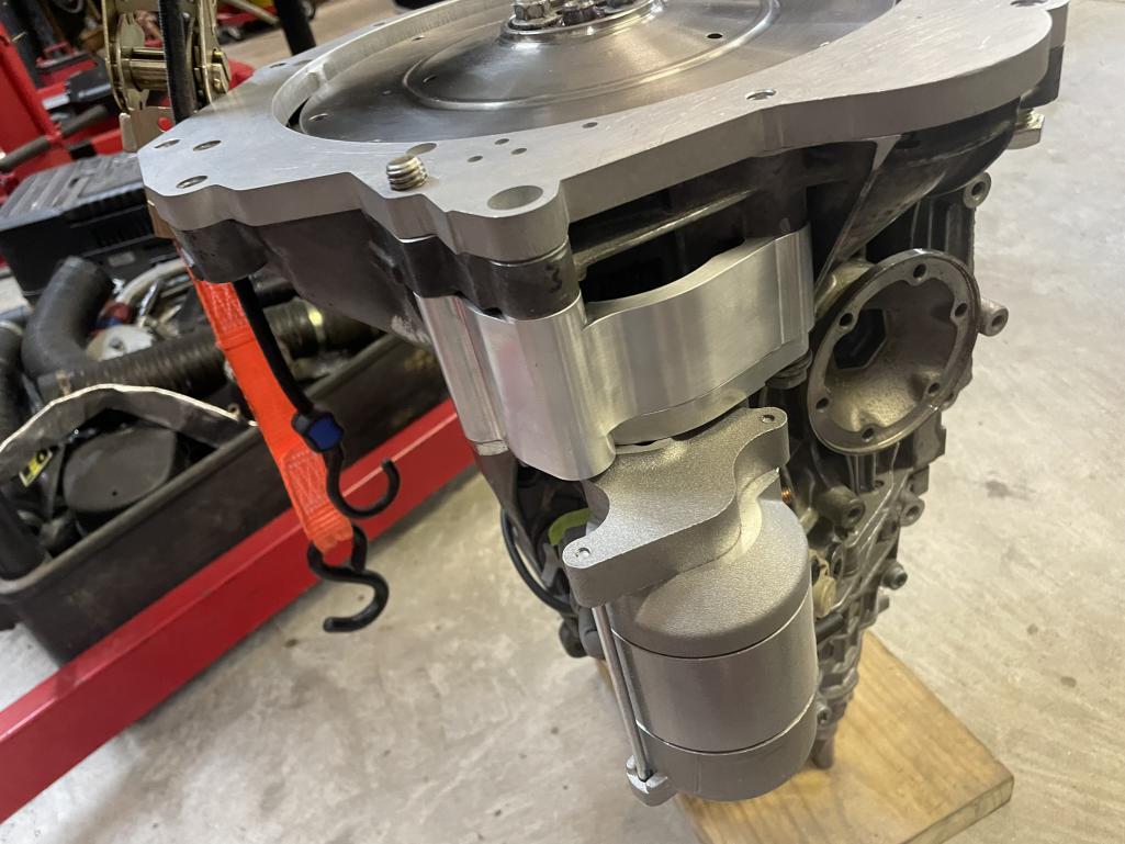 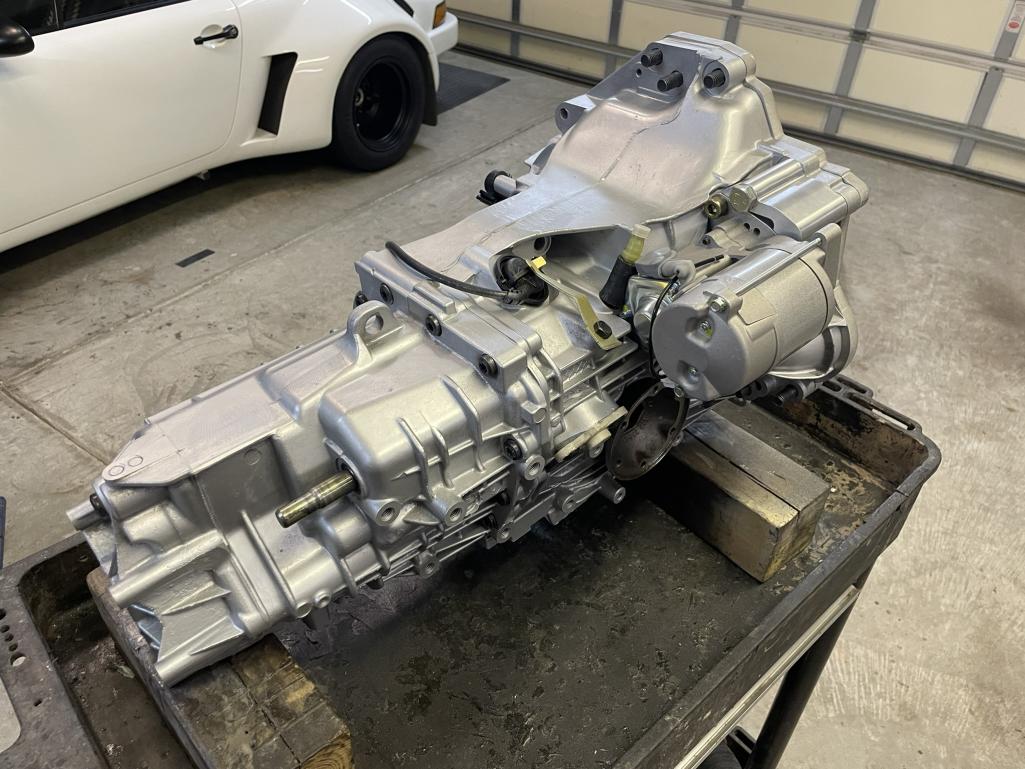 |
| technicalninja |
 Nov 23 2024, 09:53 AM Nov 23 2024, 09:53 AM
Post
#389
|
|
Advanced Member     Group: Members Posts: 2,006 Joined: 31-January 23 From: Granbury Texas Member No.: 27,135 Region Association: Southwest Region 
|
On to the transmission...The first challenge was to create an adapter that goes from the 911 engine to the 012 bellhousing. So I bought some giant digital calipers and spent a bunch of time measuring. Since there will be a certain amount of error in this, I 3D printed it a couple times to get it dialed in. Then I uploaded it to send cut send and got one cut out of acrylic. Still another could of adjustments and I ordered one from them made from 1/2" 6061 aluminum. It is a little tricky because I needed to step it up past the oil cooler on the driver's side. According to my measurements, the input shaft on the 901 transmission sticks out 10mm past the face of the bellhousing. The 012 transmission has the input shaft recessed by 9 mm relative to that surface. This means you have to cut 19mm plus the thickness of the adapter plate off the bellhousing of the 012 transmission. (31.7 mm). I did this and leveled it out using a dial guage to within 0.005" relative to the input shaft by hand. I also cut the hole for the starter and its adapter. How did you cut the bell housing? Will the throw out bearing "travel" work with that much cut off? Nicely done! |
| mfor1000 |
 Nov 23 2024, 09:56 AM Nov 23 2024, 09:56 AM
Post
#390
|
|
Newbie  Group: Members Posts: 20 Joined: 26-July 22 From: Mooresville, NC Member No.: 26,718 Region Association: South East States |
Next up: bolting everything together and checking the depth of the input shaft into the pilot bushing in the flywheel. Luckily, the hole in the side of the bellhousing (for the starter) makes this step a whole lot easier—it’s like a built-in inspection window!
And hey, it turns out I can still do math! Who knew all those measurements and calculations would pay off? 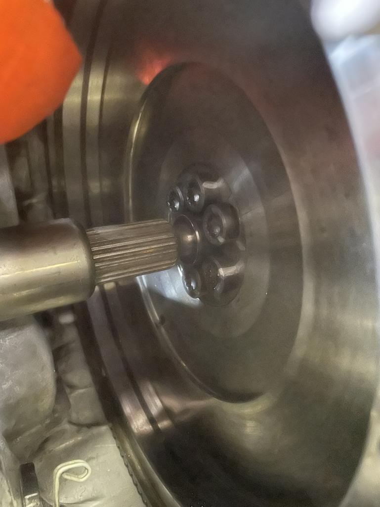 |
| mfor1000 |
 Nov 23 2024, 10:15 AM Nov 23 2024, 10:15 AM
Post
#391
|
|
Newbie  Group: Members Posts: 20 Joined: 26-July 22 From: Mooresville, NC Member No.: 26,718 Region Association: South East States |
For the clutch disk, I found an audi disk that was 9" in diameter. This had the right splines for the input shaft on the 012, and my flywheel was for a 9" disk on the engine side:
Here was the description on the ebay item I found: CP31223 Clutch Disc For Audi O.D: 9"; Spline: 15/16"; Teeth: 23 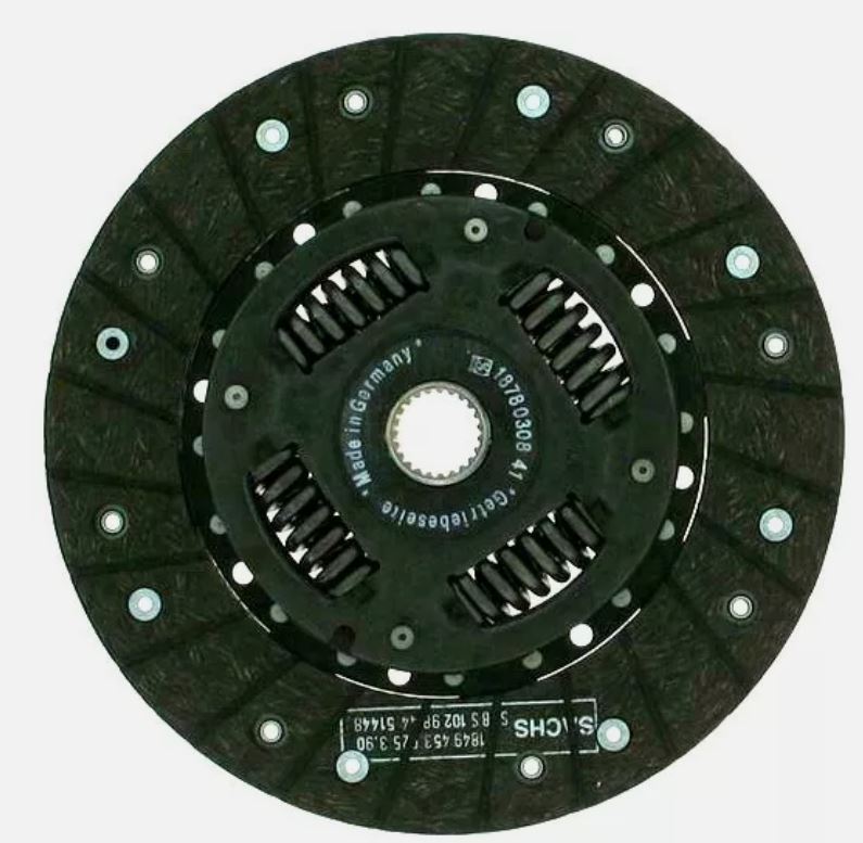 I then bolted on the pressure plate to check the clutch fork engagement. 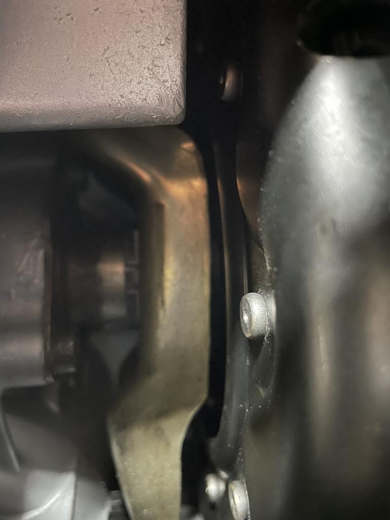 I hooked up a master cylinder (Wilwood 3/4") in a vise with a long lever and bled the lines to see if it would disengage. 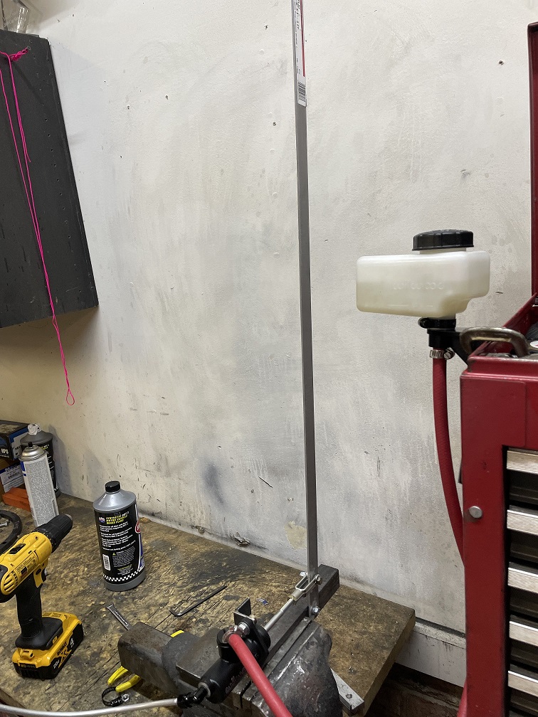 It did not, and there was about 9 mm of space before the fork would even touch the fingers. I cut and welded the shift fork to move the throwout bearing forward. 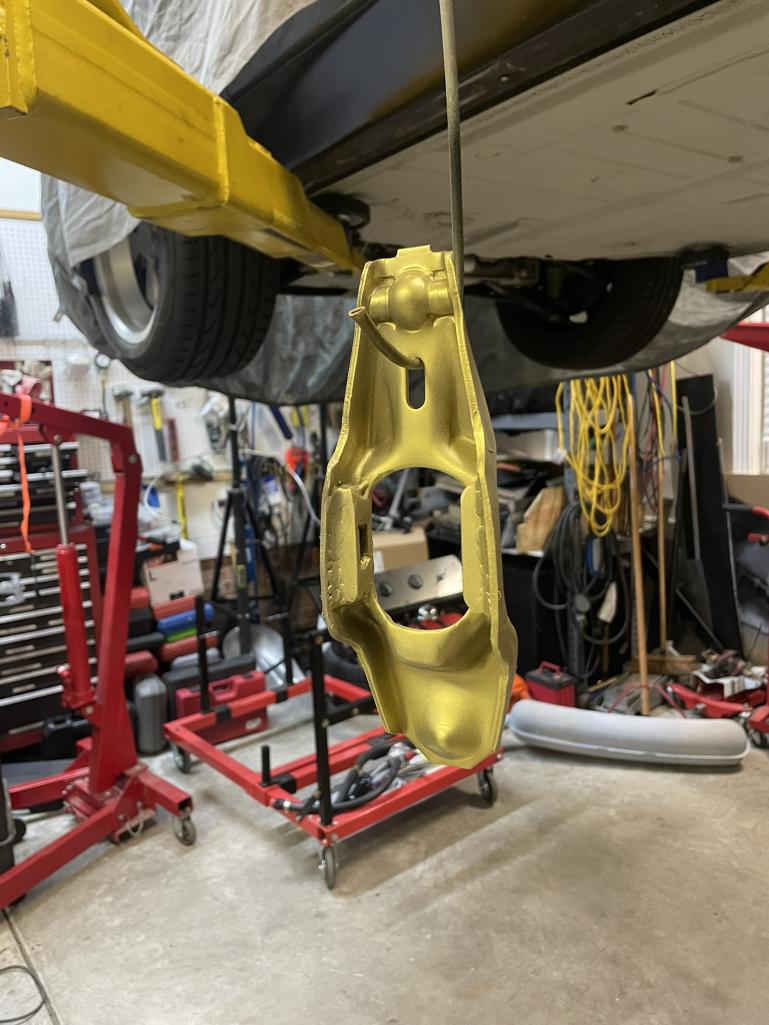 This worked and now it would release the clutch. |
| tygaboy |
 Nov 23 2024, 10:17 AM Nov 23 2024, 10:17 AM
Post
#392
|
|
914 Guru      Group: Members Posts: 5,452 Joined: 6-October 15 From: Petaluma, CA Member No.: 19,241 Region Association: Northern California 
|
Nice job on the harness and dbw set up - very cool. And did you do your own tuning? I'm just starting in on the wiring/set up of a Nexus R5 and PD-16 on my 914 Ferrari build and I'm looking to speak with some Haltech experts. Can you provide any contacts? Thanks and keep up the great work.
|
| mfor1000 |
 Nov 23 2024, 10:21 AM Nov 23 2024, 10:21 AM
Post
#393
|
|
Newbie  Group: Members Posts: 20 Joined: 26-July 22 From: Mooresville, NC Member No.: 26,718 Region Association: South East States |
The next challenge was figuring out how to mount the master cylinder in the car. I decided to stick with the original pedal cluster for this. Normally, the clutch arm pulls on a cable, but it can also be set up to push a master cylinder mounted inline with it—perfect for what I needed.
To make this work, I designed a mount that sandwiches the curved shape of the firewall in this area. Not only does this provide plenty of strength, but it also seals up nicely, meaning I didn’t have to add any additional reinforcements. It’s a clean and sturdy solution that keeps things looking tidy while doing the job right. I also uploaded the designs for these parts to PCBway and and this time had them gold anodized for some bling... 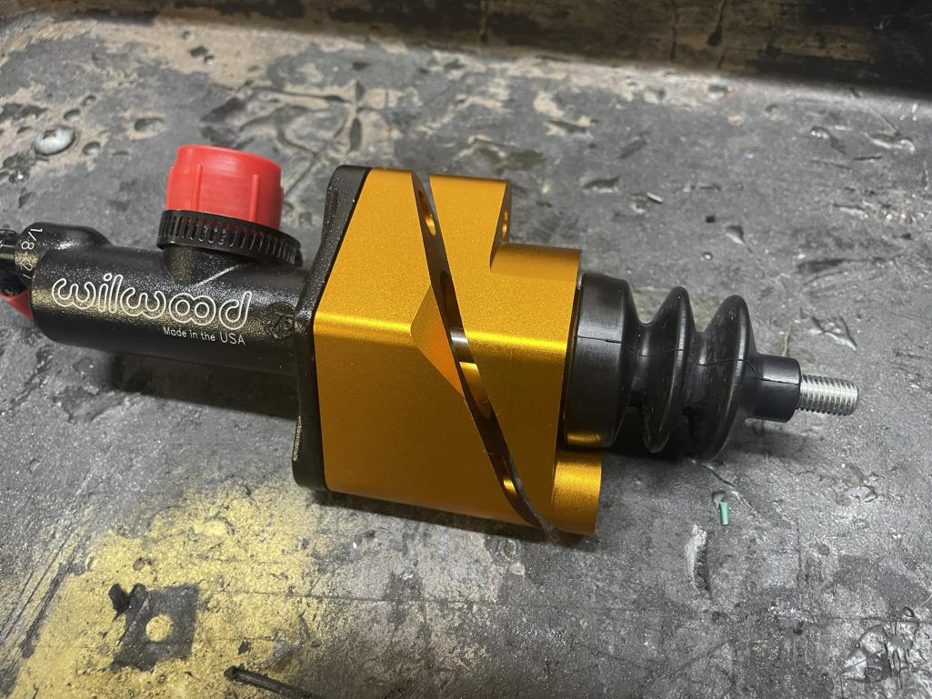 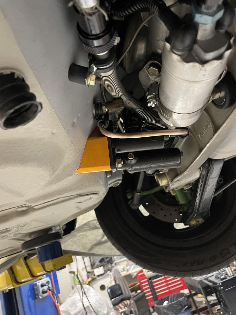 |
| mfor1000 |
 Nov 23 2024, 10:28 AM Nov 23 2024, 10:28 AM
Post
#394
|
|
Newbie  Group: Members Posts: 20 Joined: 26-July 22 From: Mooresville, NC Member No.: 26,718 Region Association: South East States |
For the clutch lines, I opted for 1/4" hard line all the way to the back. I wanted to minimize any flex in the system, and the 1/4" line ensures very little restriction since clutch systems move significantly more fluid than brake systems.
At the rear, I transitioned to a braided line connected to a dry break, which then runs to the slave cylinder. The dry break is a game-changer—it means I can pull the engine without needing to re-bleed the clutch every time. This setup combines reliability, performance, and convenience in one tidy package. 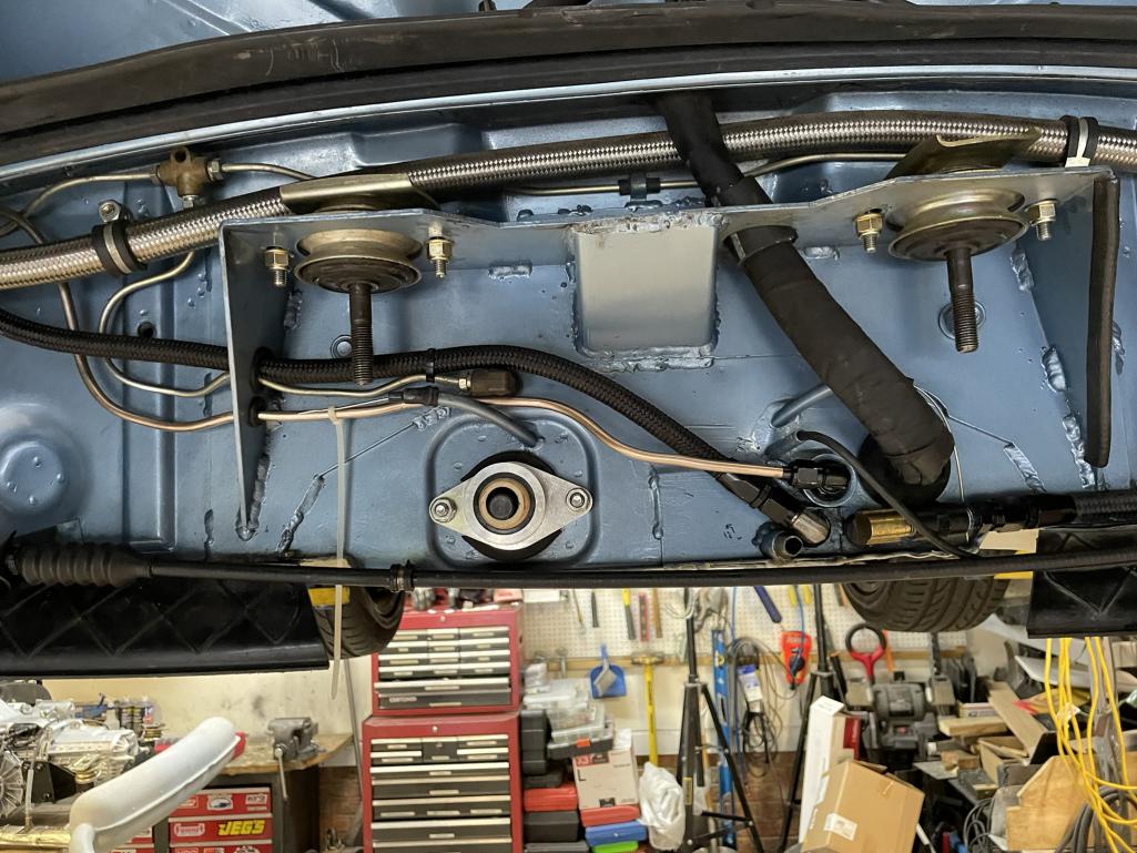 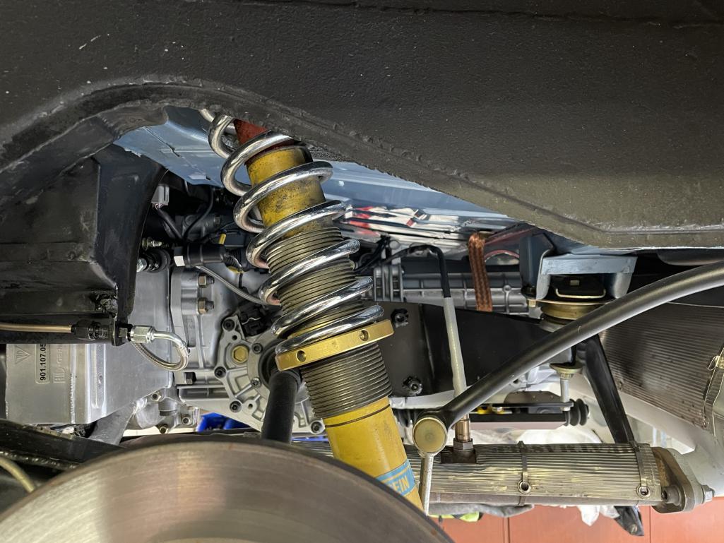 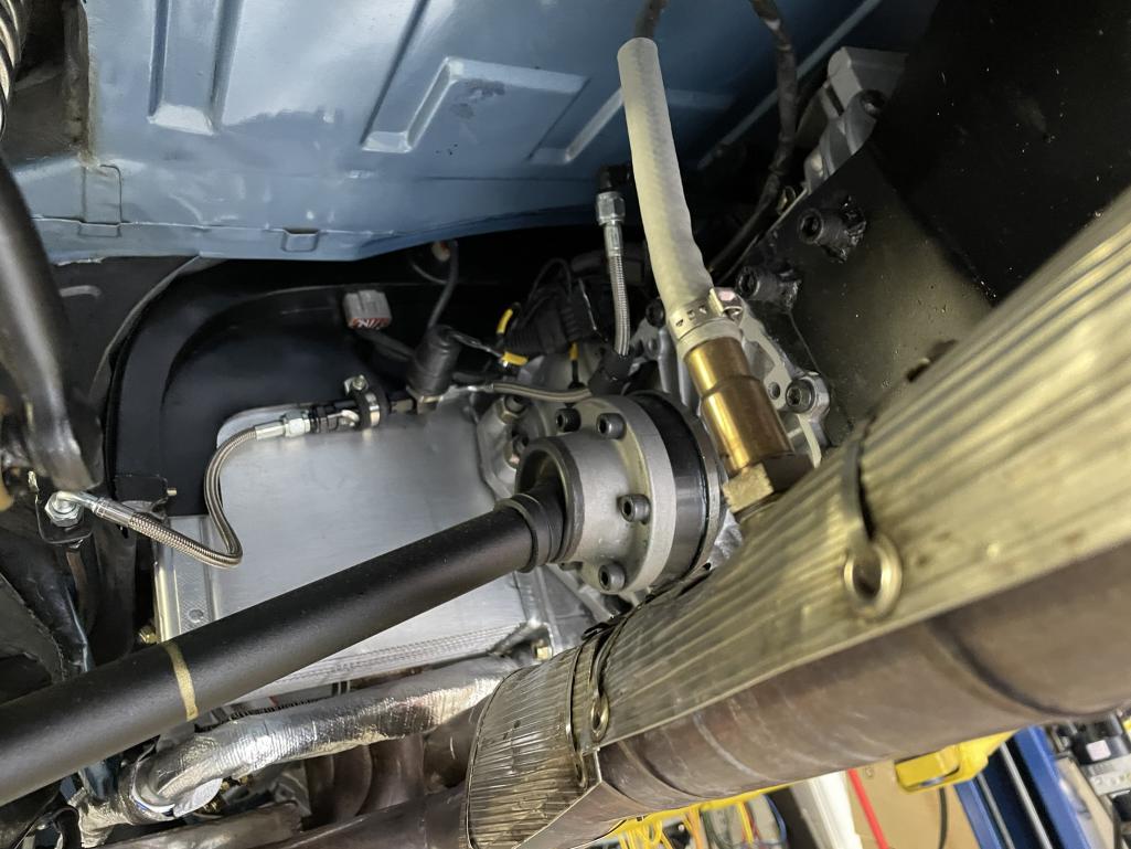 |
| mfor1000 |
 Nov 23 2024, 10:48 AM Nov 23 2024, 10:48 AM
Post
#395
|
|
Newbie  Group: Members Posts: 20 Joined: 26-July 22 From: Mooresville, NC Member No.: 26,718 Region Association: South East States |
Oh, I almost forgot to share how I tackled the rear transmission mounts! With the engine and transmission supported from below, I started by bolting four steel spacers on each side of the transmission, using the standard mounting holes. For the usual transmission mounts, I added larger spacers to get everything aligned properly.
Next, I cut some 1/8" steel plate and bent it to span the gap between the spacers. After marking and drilling the necessary holes, I welded the whole assembly together. The result is a sturdy, custom mounting solution that fits perfectly and keeps everything secure. Notice the 3D printed thing in the background...foreshadowing... 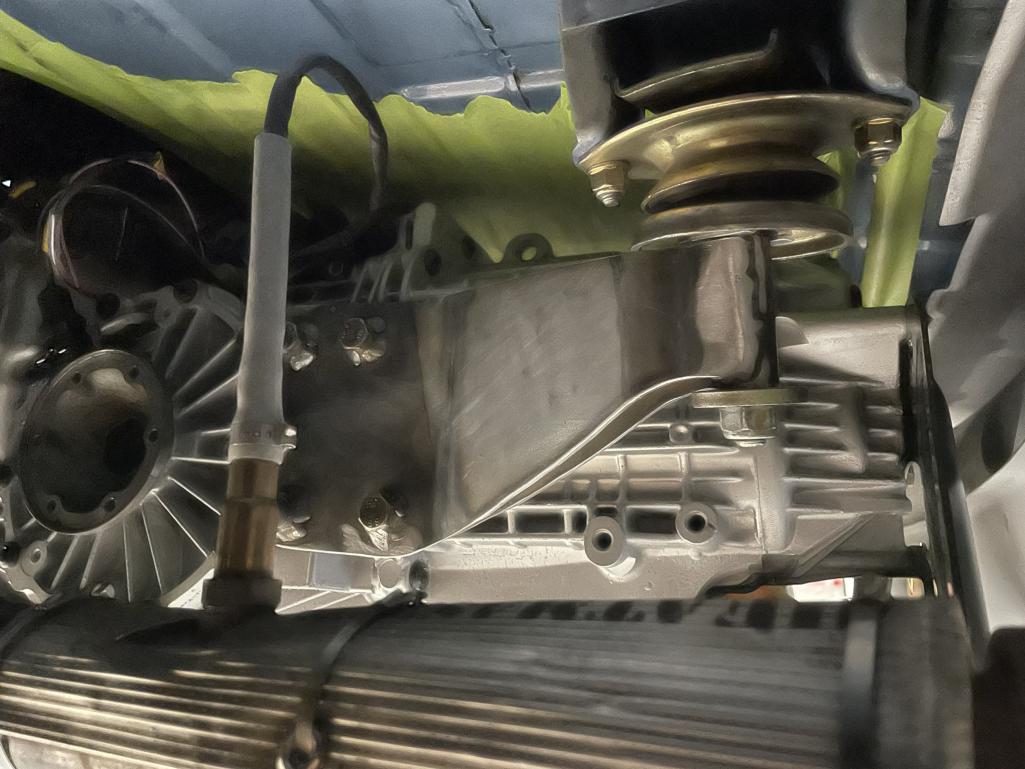 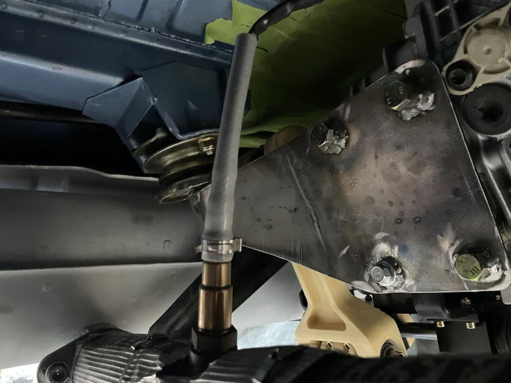 |
| mfor1000 |
 Nov 23 2024, 11:07 AM Nov 23 2024, 11:07 AM
Post
#396
|
|
Newbie  Group: Members Posts: 20 Joined: 26-July 22 From: Mooresville, NC Member No.: 26,718 Region Association: South East States |
Time to get serious about the shifter mechanism! On this transmission, the shifter input shaft sits high on the passenger side. In the Boxster, a bellcrank and cables were used to actuate it, but I wanted something more direct, without the friction and vagueness that come with cables.
To achieve this, I mounted a parallel shaft along the bottom of the transmission, supported by ceramic linear bearings. The original shifter shaft connects to this parallel shaft using steering universal joints. To minimize friction, I lubricated the linear bearings with ATF. To link the parallel shaft to the transmission’s shifter input, I designed a custom dogbone. This piece uses preloaded angular contact and Torrington bearings to eliminate play and minimize friction. The entire assembly is sealed with 3D-printed caps, keeping everything lubricated and clean. It took several 3D-printed iterations to get it just right, but once I had the final design, I sent it off to PCBWay for CNC machining and had it anodized in gold—for a little extra bling, matching the car’s cadmium-plated parts. Notice the counter-weight opposite the dog bone. With all the play eliminated, I realized the shifter mechanism needed an additional degree of freedom at the shifter itself. So, I went back to the drawing board and designed a new part to make it work perfectly. Here is a CAD animation of the mechanism...mounts have changed, but you get the idea... 012 Shifter Mechanism 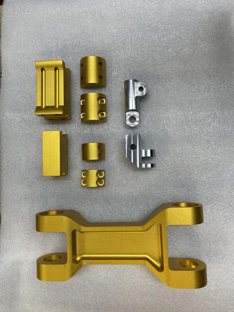 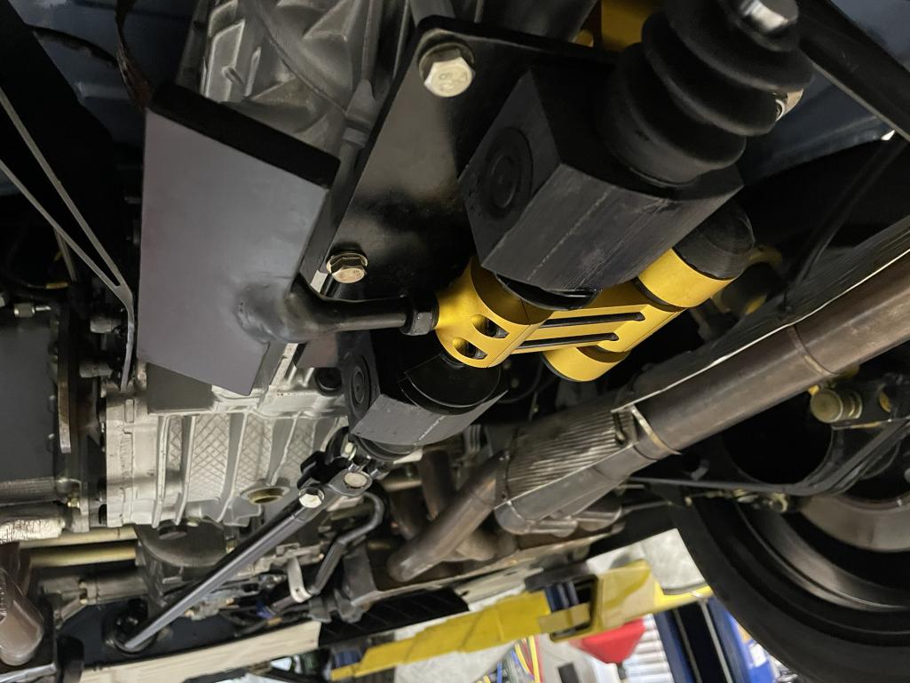 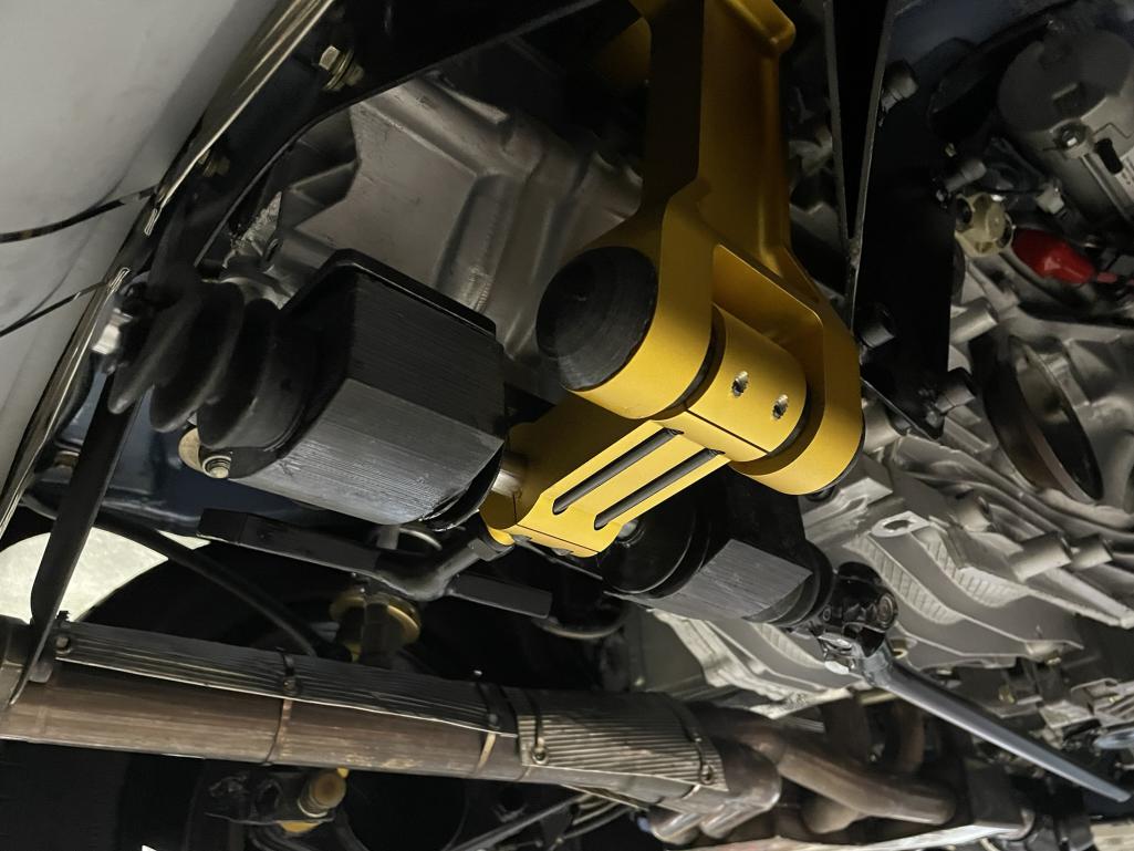 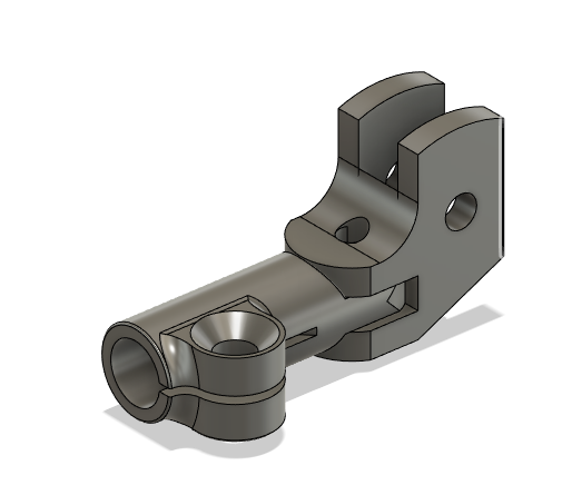 |
| mfor1000 |
 Nov 23 2024, 11:11 AM Nov 23 2024, 11:11 AM
Post
#397
|
|
Newbie  Group: Members Posts: 20 Joined: 26-July 22 From: Mooresville, NC Member No.: 26,718 Region Association: South East States |
Results?
Here is a video showing how easy and precise the shifting is: https://youtube.com/shorts/hxAmGx8OoeI?feature=share Here is the mechanism from under the car: https://youtube.com/shorts/7Vnh1kx4XxA?feature=share |
| mfor1000 |
 Nov 23 2024, 11:23 AM Nov 23 2024, 11:23 AM
Post
#398
|
|
Newbie  Group: Members Posts: 20 Joined: 26-July 22 From: Mooresville, NC Member No.: 26,718 Region Association: South East States |
Oh, and since it is drive by wire, it was relatively easy to add cruise control. This is nice for me since I tend to drive too fast when my mind wanders. I used a stock 911 cruise control stalk. I 3D printed a housing that blends in pretty well.
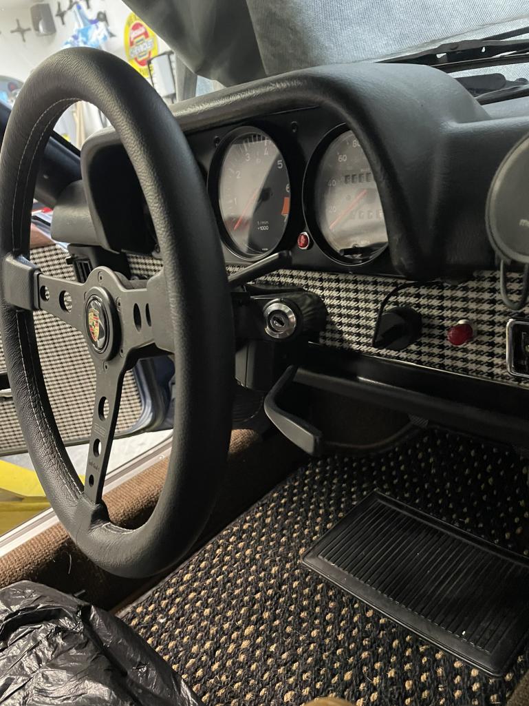 I've been driving it now for about 3 weeks on and off and it is pretty sorted out. The dyno tune ran great right away and the wide band O2 sensors have been dialing in all the puttering around stuff. It is really a pleasure to drive now. The clutch is light and quick and so are the shifts. The throttle blips are very satisfying. I'll do a driving video soon... |
| mfor1000 |
 Nov 23 2024, 01:58 PM Nov 23 2024, 01:58 PM
Post
#399
|
|
Newbie  Group: Members Posts: 20 Joined: 26-July 22 From: Mooresville, NC Member No.: 26,718 Region Association: South East States |
Here are some driving videos:
Cold Start Longer Drive Sorry, you can hear the phone rubbing against the leather a bit in the video. It was very professionally taped to the back window. |
| mfor1000 |
 Nov 23 2024, 02:11 PM Nov 23 2024, 02:11 PM
Post
#400
|
|
Newbie  Group: Members Posts: 20 Joined: 26-July 22 From: Mooresville, NC Member No.: 26,718 Region Association: South East States |
|
  |

|
Lo-Fi Version | Time is now: 24th November 2024 - 11:53 AM |
Invision Power Board
v9.1.4 © 2024 IPS, Inc.


